User Manual - EAGL Gunshot Detection System 1
←
→
Page content transcription
If your browser does not render page correctly, please read the page content below
EAGL Gunshot Detection System

                              User
                             Manual
                                                              2/6/2021

                                                                1
(V1.8 – V2.0) and (V2.1) Previous version(s) are superseded
©EAGL Technology, Inc., All rights reserved.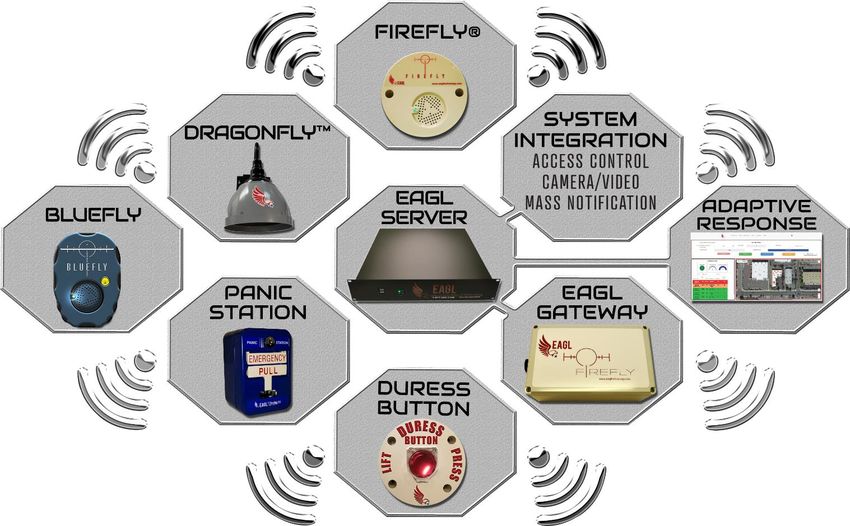
The EAGL System is fully automated and designed to respond immediately during an active shooter
threat situation providing both notification and facility lockdown features.
System operation allows easily viewable information with real-time system control. Both system
status and event information are presented and recorded in real-time. Additionally, the User can
immediately control facility access via “Soft Controls” visible on the system monitor screen using
“Point-N-Click” technology.
To fully understand the EAGL System’s capabilities and features, we recommend reading this manual
in its entirety prior to system operation.

**NOTE: If you are viewing this as a soft document, the page numbers are hyperlinks allowing
immediate access to review selected sections.

                                       Table of Contents
           USER LEVEL
           Copyright Notice, Trademarks & Revision History……..……….…..……....3
           Section 1: EAGL System Description………………..……………………………….4
          Section 2: System Accessibility Levels………….……………………………………7
          Section 3: GUI Interface Screen Familiarization…………….….….…………..8
           Section 4: Soft Controls………………………………………………………………….13
           Section 5: Troubleshooting………..……………………….………………………….20
           Section 6: Warranty Information & Disclaimer……………….………………21

                                                                                                     2/6/2021

                                                                                                       2
(V1.8 – V2.0) and (V2.1) Previous version(s) are superseded
©EAGL Technology, Inc., All rights reserved.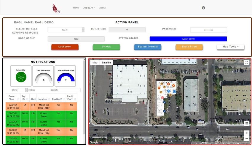
Copyright Notice

All materials in this document are the intellectual property of EAGL Technology, Inc. Our products
are under continual improvement. Although we take great care preparing the documentation
accompanying our products, EAGL Technology, Inc. offers no guarantee regarding absolute content
correctness.

No part of this manual can be reproduced without authorization by the expressed written consent
from EAGL Technology, Inc.

Trademarks

All Trademarks are recognized as the properties of their respective owners.

Releases & Revision History

    Version                              Date
Publication V2.0                       2021/02
Firmware Series V1.8 – 2.0             2019/04
Firmware Series V2.1 – 2.1.33          2020/12

               The EAGL Gunshot Detection & Lockdown System has data logging
               capabilities to record detected threat information. Although this
               information is exportable, the EAGL System does NOT currently have
               additional data backup options. Data deleted before exporting is NOT
               recoverable.
                                                                                                     2/6/2021

                                                                                                       3
(V1.8 – V2.0) and (V2.1) Previous version(s) are superseded
©EAGL Technology, Inc., All rights reserved.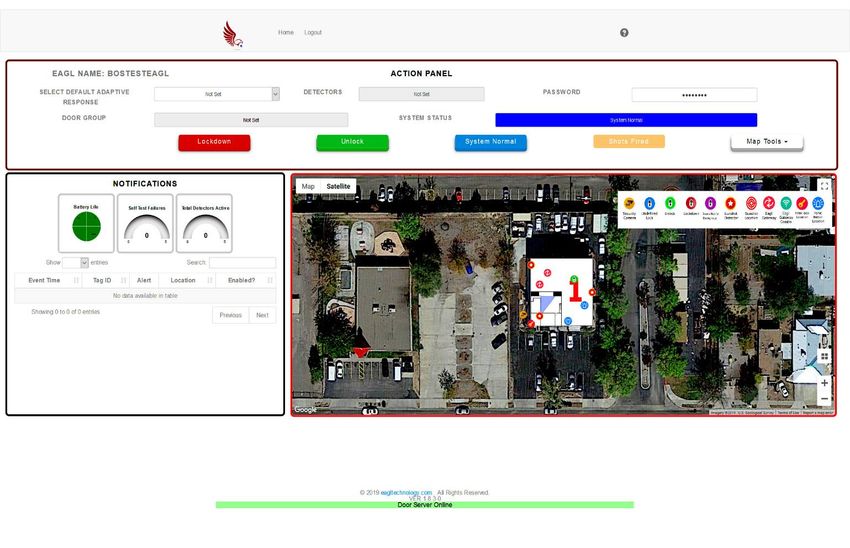
Section 1: EAGL System Description
The EAGL Gunshot Detection & Lockdown System uses fully automated equipment designed to
provide an immediate adaptive response to an active shooter threat. This system detects gunshots
within deployed areas and relays gunshot detection information to integrated third-party system
components capable of controlling not only facility access but also can provide NOTIFICATIONS to law
enforcement agencies with threat assessment information. Additionally, this system can disseminate
threat assessment information via email to text to assignees. Thus, the EAGL System responds almost
instantaneously to active shooter threats by providing both access control and notification features.
The EAGL System can be constructed in various configurations to include integration options for
existing access & alarm systems and components. A basic EAGL Gunshot Detection & Lockdown
System can consist of an EAGL Server, a Gateway and several FireFly® Indoor and / or DragonFly™
Outdoor Sensors. All major components will have affixed identification info which is needed for
system configuration.

                                                Photo 1, EAGL System Server
EAGL Server provides system control through the preprogrammed “Adaptive Responses” and the
Graphical User Interface (GUI) where both system configuration and control functions are performed.
The unit is self-contained and integrates with existing Cat 5 through Cat 6e ethernet systems. The
EAGL Server receives threat detection data from Gateways which wirelessly connect 1 to the FireFly®
Indoor and DragonFly™ Outdoor Sensors.

           Photo 2, FireFly® Indoor Sensor                              Photo 3, DragonFly™ Outdoor Sensor
The EAGL System uses proven science developed by the Department of Energy. The result of this
science produced a patented technology, used in both the FireFly® Indoor and DragonFly™ Outdoor
Sensors. Integrating these sensors with the EAGL Gunshot Detection & Lockdown System allows the
                                                                                                                2/6/2021

system to detect, validate and process threat assessment data.
1
    Typical equipment configuration based upon customer need, options available (Legacy - RF, LoRa or radio).

                                                                                                                  4
(V1.8 – V2.0) and (V2.1) Previous version(s) are superseded
©EAGL Technology, Inc., All rights reserved.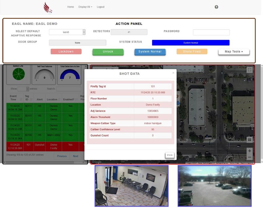
Section 1: EAGL System Description (cont.)
The Duress Button allows for manual input to the EAGL System as the alert or “Duress” signal sent to
the EAGL system is treated as a unique energy detector input with the resultant pre-programmed
protocols to be acted upon by the system. Actions can include access control, live camera streaming
and ancillary equipment functions. The Duress Button allows for “direct access interface” which can
be useful in many workplace environments and situations.

                        Photo 4, User, FireFly® Duress Button – Closed & Open Cover Views

The views presented above display the cover both closed and open, either not allowing or allowing
button access, respectively. When the cover is open, the RED button can be engaged. This engaging
action will be displayed on the User Interface screen with the input being treated as a threat
condition. The preprogrammed adaptive response will be initiated along with all associated
NOTIFICATION actions.

The FireFly® Duress Button contains no user serviceable parts. Only the battery can be replaced.

Although the Duress Button has the ability to provide a degree of portability, it is designed to be
attached to a substrate using appropriate fasteners via two through-hole locations on the device.

**NOTE: The purpose of the cover is to prevent inadvertent / accidental switch
function as both an alarm condition will activate along with ALL the programmed
NOTIFICATION features!
                                                                                                       2/6/2021

                                                                                                         5
(V1.8 – V2.0) and (V2.1) Previous version(s) are superseded
©EAGL Technology, Inc., All rights reserved.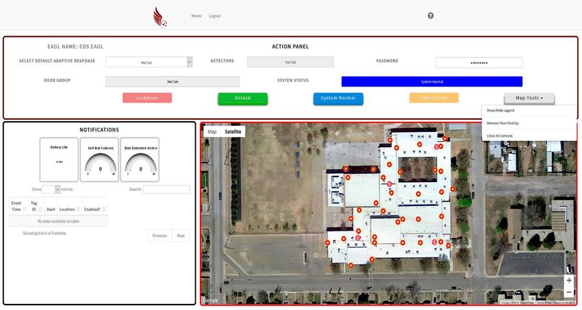
Section 1: EAGL System Description (cont.)

               A                                           B                                         C
              Photo 5, User, Panic Station – (A) Operational State, (B) Latched, and (C) Resetting Views

The photo above shows the Panic Station device that can be associated with the EAGL System. This
device purpose is similar to the Duress Button inasmuch as providing a system input representing a
threat, but device operation is completely different.
The item identified as View A shows the station in its operational state and ready for activation. The
station may be recessed in a wall or attached to a wall or other substrate surface. Station operation
consists of pushing the bar labelled “EMERGENCY” inward, grasping the “PULL” bar and pulling this
bar in a downward motion. This action latches the “PULL” bar as presented in View B and also
represents when a signal is transmitted to the EAGL System indicating a threat condition. Once the
station is latched, it can only be reset when an authorized party inserts and operates a station key,
View C, which opens the station faceplate allowing the “PULL” bar to be moved back into a ready or
operational state as depicted in View A.

**NOTE: The Panic Station operates similarly to a Fire Pull Station whereas, the
“PULL” bar needs to be placed and latched in a downward condition to initiate a
Panic signal for processing by the EAGL System. This is ONLY designed for manual
reporting of a threat condition which is NOT Fire related!
                                                                                                           2/6/2021

                                                                                                             6
(V1.8 – V2.0) and (V2.1) Previous version(s) are superseded
©EAGL Technology, Inc., All rights reserved.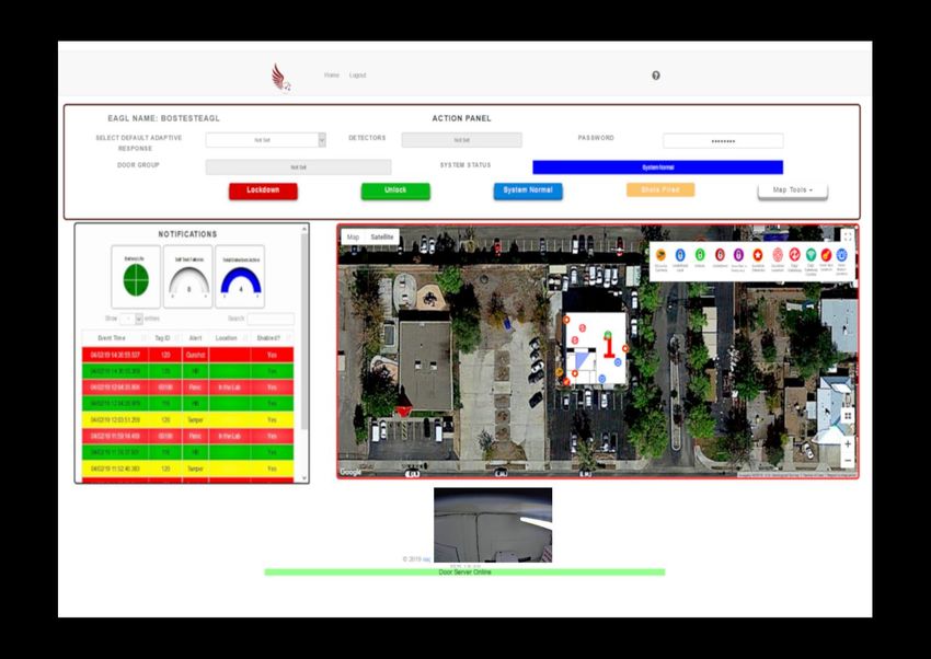
Section 2: System Accessibility Levels
The EAGL Gunshot Detection & Lockdown System uses a system access hierarchy consisting of four
distinctive interface levels. Those levels are: Viewer, Basic User, Administrator, and Integrator.
Each interface level provides tiered system access control either enabling, disabling, or offering
specific system features. Each system hierarchy level is explained below.
Viewer: This level only allows viewing of the area having EAGL coverage. There are no manual
interface functions associated with this level.
Basic User: This level provides the most basic interface features. Although this level limits
accessibility to system administration, integration and other functional protocols, all system
monitoring capabilities are operational. Lockdown and Shots Fired Testing is available at this level!
Administrator: This level allows administrator functions that are not available at the Basic User
level. This level allows accessibility to control and monitor system functions in addition to adding or
removing system Users, setup threat detection email to text messaging capability, view, export shot
(threat detection) data and enabling or disabling FireFly® Indoor and DragonFly™ Outdoor Sensors.
Integrator: This tier level provides the highest order of system access and is reserved for use by the
system installer and system manufacturer ONLY.

                                          Figure 1, User LOGIN Screen

**NOTE: All User levels, except Viewer, use “Point-N-Click” technology to enable or
                                                                                                          2/6/2021

disable system features via “Soft Buttons” on the GUI Interface. System sign-in
credentialing determines available functionality and access levels!

                                                                                                            7
(V1.8 – V2.0) and (V2.1) Previous version(s) are superseded
©EAGL Technology, Inc., All rights reserved.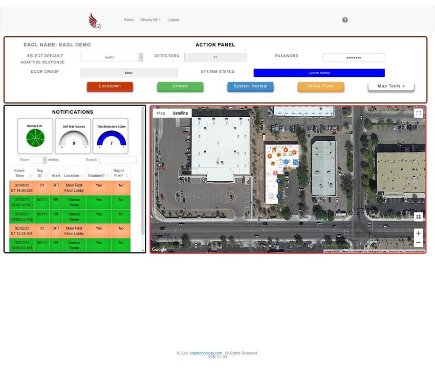
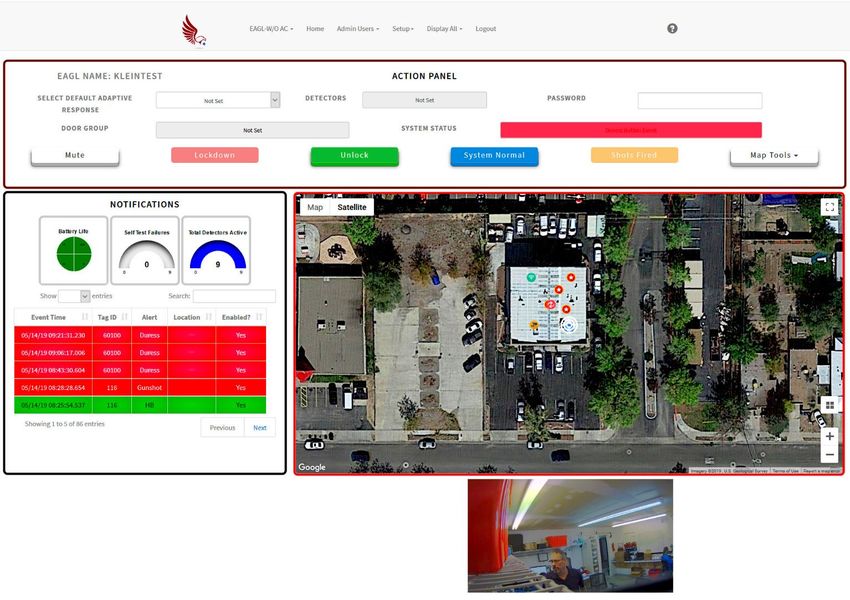
Section 3: GUI Interface Screen Familiarization
3.1 – System Display – GUI Presentation, Action Panel
Here is an example of the EAGL System Graphical User Interface (GUI) presentation when the EAGL
System is operating. The screen is comprised of three sections or panels:

                                              ACTION PANEL

                            Figure 2, User Level, GUI Interface Familiarization Screen
    NOTIFICATIONS                                                                        AREA MAP
The ACTION PANEL section allows User interface with system controls in addition to presenting real-
time system status. This section contains the following items: SYSTEM STATUS bar, ADAPTIVE
RESPONSE Defaults, DETECTORS bar, DOOR GROUP bar, PASSWORD, “Soft Buttons”: LOCKDOWN,
UNLOCK, SYSTEM NORMAL, SHOTS FIRED & MAP TOOLS.
The NOTIFICATIONS section displays additional system status information concerning detector
Battery Life, Self-Test Failures and Total Detectors Active. Options include selecting displayed data
log entries and the ability to search/sort by Event Time, Tag ID, Alert & Location.
                                                                                                        2/6/2021

**NOTE: It is recommended to adjust monitor resolution settings so displayed NOTIFICATION items
are not stacked and logged data appear truncated!

                                                                                                          8
(V1.8 – V2.0) and (V2.1) Previous version(s) are superseded
©EAGL Technology, Inc., All rights reserved.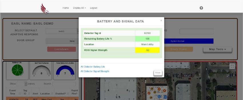
Section 3: GUI Interface Screen Familiarization (cont.)
3.2 – System Display – Notifications, Shot Data window
This window is presented when the User selected or clicked on the Gunshot alert in the
NOTIFICATIONS panel which displays Real Time sensor status. Upon selection, additional SHOT DATA
information is displayed.

                                          SHOT DATA Window
              USER Selection

                                 Figure 3, User, Notifications, Shot Data window

Clicking on “CLOSE” or anywhere outside the window closes the “SHOT DATA” window.
                                                                                                   2/6/2021

**NOTE: After closing the SHOT DATA window, a camera view can also be selected. This will be
presented in Section 4: Soft Controls.

                                                                                                     9
(V1.8 – V2.0) and (V2.1) Previous version(s) are superseded
©EAGL Technology, Inc., All rights reserved.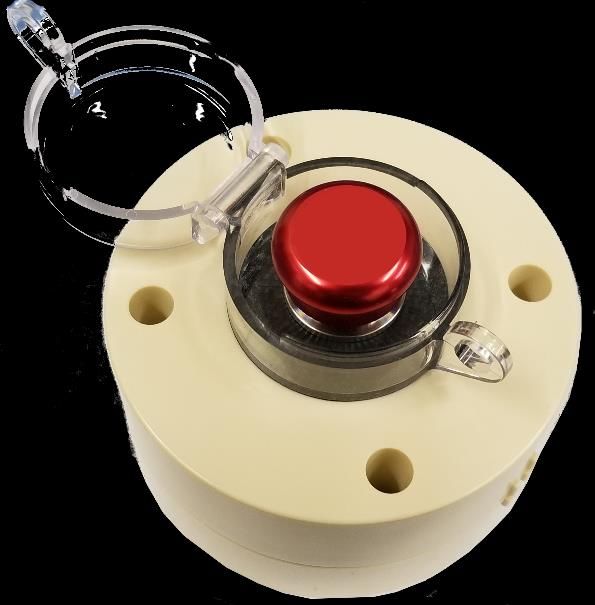
Section 3: GUI Interface Screen Familiarization (cont.)
3.2 – System Display – Notifications Panel, Battery and Signal Data window

                           Figure 4, User, Notifications, Battery and Signal Data screen
The Battery Life icon on the NOTIFICATIONS panel is multifunctional as it can portray sensor battery
levels either at a glance (Default) or when an individual sensor is selected within the Battery Life icon.
There are three color assignments for Sensor Battery Life indications, GREEN (31-100%), YELLOW (11-
30%) and RED (0-10%). These indicators allow for rapid visual assessment of estimated current
sensor battery conditions, enhancing sensor maintenance scheduling, and can also aid in sensor
troubleshooting.

**NOTE: Battery Life represented above is based on the number of predetermined heartbeats
FireFly® and DragonFly™ Sensors provide on a daily basis. In this case the number shown is
indicative of sensors sending the EAGL System Server one heartbeat during a 24-hour period.

When selecting a particular sensor, this figure will open. The displayed table lists sensor
identification, location information and RSSI Signal Strength making this feature another useful
troubleshooting aid.

RSSI Signal Strength is also colorized to indicate power level as being acceptable - GREEN, cautionary -
YELLOW or unacceptable - RED. If the associated sensor power level is consistently registering as
cautionary or unacceptable, it may mean there is a high level of electromagnetic interference (EMI)
which may cause sensor communication to become unreliable whether for heartbeat or threat
reporting. This condition may require sensor relocation.
                                                                                                             2/6/2021

                                                                                                             10
(V1.8 – V2.0) and (V2.1) Previous version(s) are superseded
©EAGL Technology, Inc., All rights reserved.
Section 5: GUI Interface Screen Familiarization (cont.)
3.2 – System Display – Notifications, Battery and Signal Data window (cont.)
Selecting “All Detector Signal Strength” option at the bottom of the window presented earlier, opens
the following screen.
Figure 5, User, Notifications, All Detector RSSI Signal Strength screen
If you are seeing sensors having RSSI values that are YELLOW or RED, please inform your system
administrator.
2/6/2021
11
(V1.8 – V2.0) and (V2.1) Previous version(s) are superseded
©EAGL Technology, Inc., All rights reserved.Section 3: GUI Interface Screen Familiarization (cont.)
3.3 – System Display – Area Map Panel
The AREA MAP section provides information relating to the EAGL Gunshot Detection & Lockdown
System coverage area. The AREA MAP section also has areas and features allowing User interface
functions. This area has two viewing modes or views, MAP or SATELLITE. There are additional
control features that allow ZOOM functions.
AREA MAP
Figure 6, User, Satellite View screen
ZOOM CONTROLS
VIEWING MODES
**NOTE: The AREA MAP default view should position the security access controlled area in the map
center!
The User screen sections mentioned have more navigation explanations and features that are
explained in Section 4: Soft Controls.
2/6/2021
12
(V1.8 – V2.0) and (V2.1) Previous version(s) are superseded
©EAGL Technology, Inc., All rights reserved.Section 4: Soft Controls
ACTION PANEL
“SOFT BUTTONS”
Figure 7, Administrator, Soft Controls screen
SYSTEM STATUS: This area displays the current system status and the color bar correlates to each
“Soft Button” color. NOTE: A “Soft Button” is active when it darkens AND APPEARS RAISED after
the password is entered! In this figure, only Unlock, System Normal and Map Tools are active.
DOOR GROUP: Represents the EAGL System monitoring of predetermined access controlled doors.
PASSWORD: Allows multilevel User interface with the system. Once a password is inputted, system
accessibility and credentialing control assigned enabling or disabling features. Figure 3, Action Panel
illustrates an example of accessibility as the 3D “Soft Buttons” displayed represent the only control
features available at this User level. NOTE: This figure illustrates that the LOCKDOWN feature is NOT
available in this instance for Basic User access as the LCKDOWN button does NOT appear in 3D!
“Soft Button” controls enable features when the cursor is placed on the feature and selected. User
level determines feature accessibility. Currently, there are five “Soft Buttons”. When they are
selected, these manual intervention inputs enable protocols to place the system either in an
activated alarm condition or disarm an activated alarm condition along with asset identification via
icons.
LOCKDOWN: Allows initiation of site-wide Lockdown (V1.8 – V2.0) or the default “Adaptive
Response” door group (V2.1) using the integrated access control system. Currently, when this feature
is selected, separate NOTIFICATION processes are NOT performed by the system, only locking doors.
UNLOCK: Allows User to unlock all site-wide access controlled doors allowing unrestricted access.
SYSTEM NORMAL: Allows User to enable the system to initiate normal, non-alarm state and return
the access control system to its normal schedule. Recommend selecting to transition system states.
SHOTS FIRED: Allows initiation of an alarm condition as if a gunshot event happened which will
lockdown controlled areas and allow NOTIFICATION processes as determined by preset protocols.
MAP TOOLS: Opens a drop-down menu with the following options: Show Legend, Hide Legend,
Floor Plans, Remove Floor Overlay as displayed below. Detector, door conditions or camera locations
are differentiated by floor.
2/6/2021
MUTE: Although only visible during an alarm condition, this button allows the operator to mute the
alarm signal at the GUI location.
13
(V1.8 – V2.0) and (V2.1) Previous version(s) are superseded
©EAGL Technology, Inc., All rights reserved.Section 4: Soft Controls (cont.)
Here is an example Map Tools drop-down menu items.
MAP TOOLS MENU
Figure 8, User, Map Tools Menu screen
EAGL SYSTEM PROTECTED AREA
In the above figure, the AREA MAP section displays the EAGL Gunshot Detection & Lockdown System
coverage area in SATELLITE view. The center of the map displays (by default) the area having system
coverage or monitored area(s) with detectors, Gateway locations and access-controlled door
condition(s).
The pull-down menu has visible options that are explained further.
2/6/2021
14
(V1.8 – V2.0) and (V2.1) Previous version(s) are superseded
©EAGL Technology, Inc., All rights reserved.Section 4: Soft Controls (cont.)
In the figure below, this viewing mode represents the MAP view. The same ZOOM controls located at
the bottom right of the map are available for use in this mode. Additionally, detector, camera and
door conditions and locations with accompanying legend are displayed.
**NOTE: If an indoor FireFly® or DragonFly™ Energy Detector validates a gunshot, the symbol
representing GUNSHOT DETECTOR will change to the GUNSHOT LOCATION icon.
MAP VIEWING MODE DETECTOR, DOOR &
ICONS LEGEND
DETECTOR, DOOR & CAMERA LOCATIONS
Figure 9, User, Map View with Icon Legend screen
The MAP viewing mode does not display area terrain or landscaping but provides a more concise and
2/6/2021
uncluttered presentation. As stated earlier, the ZOOM control can also be used in this mode to
expand the area surroundings to include nearby buildings, roads and infrastructure.
15
(V1.8 – V2.0) and (V2.1) Previous version(s) are superseded
©EAGL Technology, Inc., All rights reserved.Section 4: Soft Controls (cont.)
This view represents the SATELLITE viewing mode. Like the preceding figure, the Legend is also visible
in this viewing mode.
Figure 10, User, Satellite View with Icon Legend screen
In this figure, the centered structure represents the controlled access area. The “1” is indicative of
the floor level.
**NOTE: The MAP & SATELLITE views will display all icons for interior and exterior cameras,
sensors, doors & conditions. If the controlled access areas include other integrated security system
equipment, these items may also be presented. The EAGL Gunshot Detection & Lockdown System
FLOORS OVERLAY menu should allow the User to select floors individually to display the sensors,
2/6/2021
other equipment and door locations on the selected floor!
16
(V1.8 – V2.0) and (V2.1) Previous version(s) are superseded
©EAGL Technology, Inc., All rights reserved.Section 4: Soft Controls (cont.)
The view presented below represents the visual display when selecting a camera that is integrated
with the EAGL Gunshot Detection & Lockdown System. The camera view is presented in real-time
and is available during all system operational modes.
Figure 11, User, GUI Screen, Video Feed
CAMERA VIEW CAMERA LOCATION SELECTED
The example presented indicates there is only one camera located near the lab of the controlled
access area. If multiple cameras are on site, clicking each individual camera icon will open a window
2/6/2021
(up to four simultaneously) at the bottom of the page displaying each selected camera’s real-time
view.
17
(V1.8 – V2.0) and (V2.1) Previous version(s) are superseded
©EAGL Technology, Inc., All rights reserved.Section 4: Soft Controls (cont.)
Up to this point, we covered multiple visual representations of the EAGL Gunshot Detection &
Lockdown System when SYSTEM STATUS was in a NORMAL condition. The graphic below represents
the visual display when the EAGL System detects a gunshot. In this example, the camera window
presents a camera view and the detector icon closest to the detected gunshot location changes to
the Gunshot Detected icon. Additionally, the camera window will open and present live video from
the nearest camera to the FireFly® Energy Detector that identified the active shooter location.
GUNSHOT DETECTION ICON
SYSTEM STATUS
Figure 12, User, GUNSHOT DETECTED screen
CAMERA VIEW
While the EAGL System is in this condition, the word “Gunshot” in the RED
SYSTEM STATUS bar will blink and there will also be an audible alarm. When this alarm condition
occurs, preset protocols are immediately enabled, and lockdown processes are initiated. System
Status bar colors correspond to “Soft Button” conditions & colors.
2/6/2021
**NOTE: A new “Soft Button” called MUTE will appear on the ACTION PANEL, on the left, during an
alarm condition. This button allows the User to ONLY disable the audible alarm at the User station!
18
(V1.8 – V2.0) and (V2.1) Previous version(s) are superseded
©EAGL Technology, Inc., All rights reserved.Section 4: Soft Controls (cont.)
The graphic below provides a magnified view of the Map Tools, Legend information.
Drawing 1, User, Expanded ICON LEGEND view
This display shows legend icons: Security Camera, System Normal, Unlock, Lockdown, Doors Not in
Door Group, Gunshot Detector, Gunshot Location, EAGL Gateway, EAGL Gateway Combo, Knox Box
Location & Panic Button.
Figure 13, User, Notifications Panel, Logged Entries
This view shows detector HB (Heartbeat) conditions indicative of detector connectivity with the
system and detector battery life. The HB signal is typically programmed to generate a signal once
during a 24-hour period. Currently, the represented Battery Life is ONLY an estimate based upon
detector transmissions and battery standby current.
2/6/2021
**NOTE: Event colors are dependent upon device, function, or condition. GREEN for HB’s, SALMON
for SFT’s, bright RED for Gunshot detection, YELLOW for Tamper and light RED for Panic Station or
Duress Button.
19
(V1.8 – V2.0) and (V2.1) Previous version(s) are superseded
©EAGL Technology, Inc., All rights reserved.Section 5: Troubleshooting
The EAGL Gunshot Detection & Lockdown System is designed for maximum longevity and
serviceability. If any system problems are encountered, please contact your system Administrator.
EAGL Technology, Inc. stands behind their products and service. Service questions should first be
directed to your system Administrator and then the Integrator/Installer who installed your on-site
system. The appropriate contact information can be recorded below.
ADMINISTRATOR: .
ADMINISTRATOR PHONE#: .
INTEGRATOR/INSTALLER: .
SYSTEM INSTALL DATE: .
2/6/2021
20
(V1.8 – V2.0) and (V2.1) Previous version(s) are superseded
©EAGL Technology, Inc., All rights reserved.Section 6: Warranty Information & Disclaimer
The EAGL Gunshot Detection & Lockdown System has a warranty program offering distinct device
warranty periods. The EAGL Server has a five (5) year manufacturer warranty period. EAGL Gateways
and Sensors each have three (3) year manufacturer warranty periods. The manufacturer warranty
period begins after system installation and system commissioning. System service questions should
be directed to the authorized system Administrator and then the Integrator/Installer who installed
your on-site system. EAGL Technology, Inc. recommends quarterly EAGL System inspections and
testing.
Equipment design predicates system purpose and functions. Do not attempt to modify, upgrade, or
replace system components if you are not an authorized Integrator/Installer or service center as
these actions will void manufacturer warranty. It is strongly recommended contacting an authorized
Integrator/Installer for any modifications, upgrades, additions, or replacement actions.
Manufacturer reserves the right to discontinue, or modify at any time, specifications or designs
without notice and without incurring obligations.
**NOTE: This manual ONLY has information regarding the EAGL Gunshot Detection
& Lockdown System basic configuration and use. Should additional site-specific add-
on equipment or system modification be needed, addendums to this manual may be
provided so that all site-specific parameters are available for system configuration,
operation, testing and troubleshooting.
DISCLAIMER
The EAGL Gunshot Detection & Lockdown System has data logging capabilities
to record detected threat information. Although some information is
exportable, the EAGL System does NOT currently have additional data backup
options. It is highly recommended to ensure Export functions are performed,
when available, prior to Deletion functions. Data deleted before exporting is
NOT recoverable.
2/6/2021
This concludes this section and manual.
21
(V1.8 – V2.0) and (V2.1) Previous version(s) are superseded
©EAGL Technology, Inc., All rights reserved.You can also read