Towards a Formal Modelling, Analysis, and Verification of a Clone Node Attack Detection Scheme in the Internet of Things - arXiv
←
→
Page content transcription
If your browser does not render page correctly, please read the page content below
Towards a Formal Modelling, Analysis, and Verification of a Clone Node Attack Detection
                                                                   Scheme in the Internet of Things

                                                                              Khizar Hameed∗, Saurabh Garg, Muhammad Bilal Amin, Byeong Kang
                                                                     a Discipline   of ICT, School of Technology, Environments, and Design, University of Tasmania, Australia

                                         Abstract
                                            A substantial component of the Internet of Things (IoT) network is made up of unmonitored IoT devices that are generally
                                         deployed in hostile situations where attackers attempt to capture and compromise them to gain control of the entire network. One
arXiv:2108.09931v1 [cs.CR] 23 Aug 2021

                                         such illustration of this malevolent behaviour on the part of an adversary is the cloning of IoT devices. In a clone node attack,
                                         an attacker attempted to physically capture the devices to gather sensitive information to conduct various insider attacks. Several
                                         solutions for detecting clone node attacks on IoT networks have been presented in the viewpoints above. These solutions are focused
                                         on specific system designs, processes, and feature sets and act as a high-level abstraction of underlying system architectures based
                                         on a few performance requirements. However, critical features like formal analysis, modelling, and verification are frequently
                                         overlooked in existing proposed solutions aimed at verifying the correctness and robustness of systems in order to ensure that no
                                         problematic scenarios or anomalies exist. This paper presents a formal analysis, modelling, and verification of our existing proposed
                                         clone node attack detection scheme in IoT. Firstly, we modelled the architectural components of the proposed scheme using High-
                                         Level Petri Nets (HLPNs) and then mapped them using their specified functionalities. Secondly, we defined and analysed the
                                         behavioural properties of the proposed scheme using Z specification language. Furthermore, we used the Satisfiability Modulo
                                         Theories Library (SMT-Lib) and the Z3 Solver to validate and demonstrate the overall functionality of the proposed scheme.
                                         Finally, in addition to modelling and analysis, this work employs Coloured Petri Nets (CPNs), which combine Petri Nets with a
                                         high-level programming language, making them more suitable for large-scale system modelling. To perform the simulations in
                                         CPN, we used both timed and untimed models, where timed models are used to evaluate performance, and untimed models are
                                         used to validate logical validity.
                                         Keywords:
                                         Clone Node, Internet of things, Formal modelling, Analysis, Verification, High level Petri Nets, Coloured Petri Nets

                                         1. Introduction                                                                     non-tempered resistant and versatile, making them easy targets
                                                                                                                             for attackers [4, 5].
                                            An emerging and promising network paradigm known as the
                                         Internet of Things (IoT) involves numerous devices connect-                            There are numerous types of attacks on IoT devices, and one
                                         ing people and objects to the internet to accomplish various                        type is a clone-node attack, also known as a device replication
                                         functions [1]. These devices are heterogeneous in nature and                        attack [6]. In a clone-node attack, the attacker can extract the
                                         are placed in a variety of environments to collect data and in-                     personal device ID, public and private keys from the IoT net-
                                         formation that is then sent to some controlling authorities, e.g.                   work and use this information to control the physical device(s).
                                         clouds, for analysis or decision-making enhancement [2]. Some                       In order to leverage this vulnerability, an attacker must first lo-
                                         of the advanced IoT-powered smart home features include ther-                       cate the physical device, collect the secret credentials, and then
                                         mostats, doorbells, security alarms, and similar automated de-                      use these credentials to manipulate the device’s function before
                                         vices, which enable people to remotely control and manage                           reinstalling it in the network [7]. Clone-node attacks are more
                                         their homes and notify them if something suspicious happens                         likely to occur if the IoT devices are not updated with the lat-
                                         in their absence. However, several risks have pervaded IoT de-                      est security software and their security certificates are outdated.
                                         vices, ranging from security threats to privacy concerns, ow-                       Additionally, the clone node attack can be used in tandem with
                                         ing to the numerous constraints imposed by their functional                         other malevolent attack vectors on the IoT network, including
                                         capabilities (processing, storage, and power) and the various                       a selective forwarding attack, wormhole attack, and blackhole
                                         design features [3]. For example, IoT devices are frequently                        attack [8].
                                                                                                                                In recent years, the surge in popularity of IoT-based specific
                                            ∗ Corresponding
                                                                                                                             applications has intensified the interest in designing and devel-
                                                          author
                                            Email addresses: hameed.khizar@utas.edu.au (Khizar Hameed ),
                                                                                                                             oping security solutions to protect IoT devices and their data.
                                         saurabh.garg@utas.edu.au (Saurabh Garg), bilal.amin@utas.edu.au                     Existing studies have been proven that a clone node attack de-
                                         (Muhammad Bilal Amin), byeong.kang@utas.edu.au (Byeong Kang)                        tection mechanism effectively protects IoT devices from adver-
                                         Preprint submitted to Journal Name                                                                                                       August 24, 2021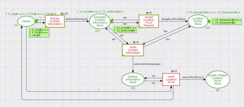
saries, as it enables systems to detect when the attacker initiates       ing the result analysis phase. Afterwards, Z-language is ap-
abnormal activity, which results in duplicate nodes being es-             plied to the systematic and behavioural characteristics of the
tablished in the network [7]. One of the effective methods to             system to model, describe and analyse. Additionally, we eval-
mitigate the risk of a clone-node attack on an IoT network is             uated the models in three-fold: (i) we applied the automated
that every device uses a data forwarding protocol to send au-             model checking technique using the Satisfiability Modulo The-
thentication messages containing all of the information of their          ories Library (SMT-Lib) and Z3 solver to perform automated
neighbours to a base station. The base station receives the mes-          verification of the models. First, the models are translated into
sage and validates it by utilising a key exclusively assigned to          SMT and the specified properties, then SMT is used to vali-
that device [9]. Some other methods for finding the cloned node           date the Petri Net models, (ii) The Z3 solver is used to exam-
attacks include finding network witnesses [6], measuring the              ine the model to see if it is adhering to the specifications, (iii)
signal strength of devices [9], randomly picking secret keys              Finally, we extend this work by modelling and analysis of pro-
[10], calculating trust values [11, 12], managing distributed             posed scheme using CPNs.
trust [13], localization algorithms [14] and multi-dimensional               To the best of our knowledge, no existing work has been
scaling [15]. A detailed analysis of existing schemes based on            conducted to formally model, analyse, and verify the detection
wireless sensor networks, IoT, and mobile ad-hoc networks for             scheme for clone node attacks on IoT networks. This work aims
detecting clone node attacks is summarised here [16].                     to demonstrate the correctness of our proposed clone node at-
   Existing clone node attack detection approaches, on the other          tack detection scheme, which will enable researchers to com-
hand, are strictly limited to the system’s architectures, includ-         prehend the design, modelling, analysis, and verification pro-
ing its functions and feature sets. Additionally, another com-            cesses required to analyse the efficient functioning of any sys-
mon trend observed in existing clone node attack detection                tem architecture and its underlying set of features.
schemes is that they provide a high level of abstraction for sys-            The following constitute the primary contributions to this pa-
tem architectures and evaluate schemes solely on well-known               per:
performance parameters such as detection rate, detection time,
and various system overhead complexities such as computa-                   • Model our proposed scheme with HLPNs and analyse the
tion, communication, and storage, without providing any mod-                  results with the help of incidence marking and confidence
elling and verification of their works to verify the correctness              intervals.
and robustness. In this work, we conducted formal modelling,
                                                                            • Analyse the proposed HLPNs using the Z specification
analysis and verification of our existing proposed clone node
                                                                              language.
attack detection scheme [16] to provide the fine-grained ab-
straction level and to ensure that our proposed scheme does                 • Provide formal verification of the proposed HLPNs and
not contain any problematic scenarios or anomalies. Our pro-                  their defined specifications and properties using SMT-Lib
posed clone node attack detection scheme uses semantic in-                    and Z3 solver.
formation about IoT devices, known as context information,
sensed from the deployed environment to locate them securely.               • Model our proposed scheme with CPNs gives the user the
Furthermore, our proposed scheme designed the location proof                  ability to design models as a hierarchy of modules sup-
mechanism by combining location proofs and batch verifica-                    porting timed and untimed simulations.
tion of the extended elliptic curve digital signature technique
(ECDSA*) to accelerate the verification process at selected                  The organisation of this paper is structured as follows: Sec-
trusted nodes. Section 2 goes into detail regarding our exist-            tion 2 provides an overview of our proposed clone node attack
ing proposed scheme and its working mechanism.                            detection scheme. The preliminaries used in this paper are dis-
   Formal verification is a systematic process that evaluates a           cussed in section 3. Section 4 presents the modelling and anal-
proposed system or approach by defining rational arguments                ysis of the proposed scheme using high-level Petri nets and Z
and determining whether or not the proposed system satisfies              specification language, respectively. Formal verification of the
the provided design, engineering, and implementation require-             proposed system along with its properties and results is illus-
ments [17]. We follow three fundamental steps of the formal               trated in the section 5. Section 6 provides the modelling and
verification process in this work: modelling, analysis, and veri-         analysis of our proposed scheme using CPNs. Finally, section
fication. First, we use HLPNs to illustrate our proposed system           7 includes the conclusion to our work.
model and information about the various components and in-
ternal links to get a detailed understanding of the design. Then,         2. An Overview of Our Existing Proposed Clone Node At-
HLPN is utilised to model the systems and present mathemat-                  tack Detection Scheme
ics to understand and analyse system behaviour and structural
properties. Moreover, the model is used to help analyse the                  This section provides an overview of our existing proposed
interconnection of the components and processes, reveal the               clone node attack detection scheme [16], including the back-
flow of information and processing of that information in-depth,          ground description, methodology with the network components
and answer how the flow of information and processing occurs.             and proposed algorithms, to assist readers in understanding the
Next, we used the PIPE+ tool to estimate the HLPNs’ esti-                 proposed scheme’s procedure and helping with the system mod-
mated incidence markers and confidence interval values dur-               elling, analysis and verification processes.
                                                                      2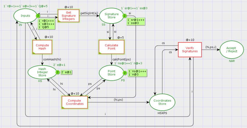
The proposed scheme leveraged context-aware systems in                 H, and domain parameters such as P, and then outputs the sig-
IoT networks to detect clone node attacks using context infor-            nature (r, s) for each device. This process started by selecting a
mation from deployed IoT devices. Context-aware systems are               random integer between 1 and n-1 for the k parameter. Follow-
IoT systems that keep track of surrounding objects and provide            ing that, a coordinate value X is then determined by multiplying
timely feedback to users. Context Information is the semantic             the random integer k by the random point P. The hash function
information that enables users to comprehend the networking               H (in this example SHA-1) takes the message m and outputs a
environment and locate network entities based on their rela-              digest string value, which is then transformed to an integer e.
tionships with the environment. The proposed scheme also in-              Finally, a signature value s is calculated by taking the inverse
tegrates location-based services (LBS) and context-aware sys-             of k random integers and multiplying the sum of integer e and
tems to track network nodes. The LBS can enable numerous                  private key d by r. The final output of ECDSA* signature gen-
services in IoT-based applications, such as tracking and moni-            eration is a pair, such as (r, s).
toring patients, tracking vehicles on the road, and determining
an individual’s actual position. LPSs are being implemented in            2.1.3. Signature Verification
IoT-based applications to create and share digitally signed con-
                                                                             An ECDSA* Signature Verification mechanism verifies the
text data to prove the user’s location at any given time. The pro-
                                                                          signer’s signatures sent with his/her public key. The verifica-
posed scheme used digital signatures to verify the authenticity
                                                                          tion process is entirely dependent on the signature size in terms
of devices or messages during communication to ensure IoT de-
                                                                          of computational time. For instance, the lengthy signature re-
vice and data security. Since the scalability of IoT networks is
                                                                          quires additional verification time. The verification algorithm
crucial in most applications, verifying individual device signa-
                                                                          requires a signature value (r, s) and a public key Q as inputs.
tures is not recommended. For this reason, the proposed scheme
                                                                          To be more specific, the signature verification output is a bi-
makes use of batch verification, which verifies digital signatures
                                                                          nary choice (accept or reject). The signature verification pro-
in batches. Batch verification is a concept that involves verify-
                                                                          cess starts by determining if the signature values r and s are in
ing multiple signatures simultaneously in order to minimise the
                                                                          the interval [1, n-1]. The hash H function then computes the
time taken to validate each signature submitted by thousands of
                                                                          hash value of the message m for comparison. Similarly to the
sensor nodes in large-scale IoT networks.
                                                                          signature generation algorithm, the hash value is converted into
   There are two primary components to the proposed scheme:
                                                                          an integer e. Further, by taking the modulus of the inverse value
an enhanced ECDSA* and a location-proof system (LPS), as
                                                                          of the signature, an integer value w is generated. Two coordi-
explained in sections 2.1 and 2.2 respectively. These two com-
                                                                          nates, u1 and u2 , are determined by multiplying the integers e
ponents help us design an HLPN-based model, which is subse-
                                                                          and r by the value w, respectively. An X value is generated by
quently verified and analysed.
                                                                          combining the multiplications of P and Q by the calculated co-
2.1. An ECDSA* Technique                                                  ordinates (u1 , u2 ) from the previous step. If X = O, the signature
   As stated above, the proposed scheme used batch verification           will be rejected; otherwise, it will be accepted if and only if υ
rather than individual signature validation to reduce verification        = r.
time. In batch verification, the signer interacts with the verifier
to generate t signatures, and the verifier validates them all at          2.2. Location Proof System (LPS)
once. An ECDSA is a widely used digital signature technique                  The LPS component used context-aware modalities localisa-
in the IoT, as it provides the same level of security as public-key       tion to detect clone node attacks on IoT networks. As the name
cryptography but requires smaller key sizes. An ECDSA* is a               implies, context-based localisation collects contextual informa-
variation of ECDSA that provides 40% improved verification                tion about the IoT device’s environment (e.g. ambient acoustic
efficiency without sacrificing security.                                  light, noise level, humidity, temperature, Wi-Fi and Bluetooth
   The ECDSA* algorithms used in the proposed scheme are                  signal power) and then use proofs to determine the device’s ex-
explained in the following sections.                                      act location. Contextual information is collected concurrently
                                                                          by devices and verifiers, with the device generating proofs of
2.1.1. Key Generation
   An ECDSA* Key Generation algorithm generates a pair of                 presence from the collected data and the verifier validating such
public and private keys for use in the signing and verification           proofs. The proposed LPS mechanism consists of the following
processes. The algorithm accepts as inputs standard domain pa-            interacting components: prover, clone node, verifier, and LBS.
rameters from elliptic curve cryptography (ECC), including p,             According to the proposed scheme, verifiers aim to inform an
E, P, n, h. These parameters are defined in the following order:          LBS about the existence of provers at a specific place to detect a
p denotes order of prime field, E denotes an elliptic curve gen-          clone node attack. A prover and a verifier collect context infor-
erated over the prime field, P denotes a non-zero random base             mation from the deployed environment. To validate the proofs,
point in E, n denotes the ordinal value of P, which is typically          the verifier IoT devices compare the context information ob-
a prime integer, and h denotes a co-factor.                               tained from the prover IoT devices to their context information
                                                                          to determine whether or not the IoT device has been compro-
2.1.2. Signature Generation                                               mised. The following sections illustrate the working of LPS
   An ECDSA* Signature Generation procedure takes the fol-                in the proposed scheme: calculate location, generate location
lowing parameters as an input such as message m, hash function            proof, and verify location proof.
                                                                      3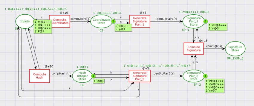
2.2.1. Calculate Location • R is a set of finite rules that map T to logical formulae,
The Calculate Location algorithm shows how to locate net- such as R: → Formula or logical reasoning
work devices. The proposed scheme calculates the location of
each device (such as the prover and verifier) by measuring the • L is the label associated with each flow as F, such that L :
distance between them in two-dimensional (2-D) space. F → Label.
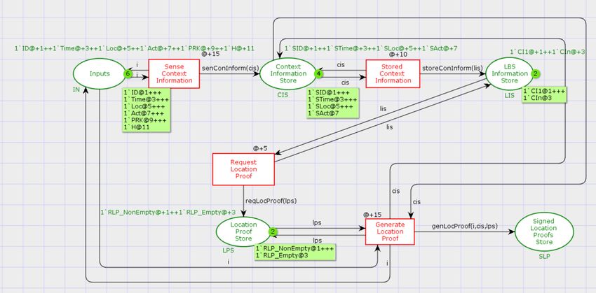
2.2.2. Generate Location Proof • M0 is the Petri Net’s start state that initiates flow and pro-
The Generate Location Proof algorithm shows how to gener- duces tokens M : P → Tokens.
ate location proofs for IoT devices based on LBS. The prover
and the verifier first collect contextual information about their The three building blocks (P, T, F) define the structure of
deployed environment. A verifier first requests the prover to Petri nets. Additionally, three blocks (ϕ, R, L) contain informa-
generate a location proof utilising sensed context information tion about the Petri net metadata that is used during implemen-
as CI. The proof is then signed using the prover’s private key tation and validation part. In HLPNs, places are represented
KPr . by circles, transitions by rectangles and directed arrows can be
used to connect places and transitions, and vice versa. How-
2.2.3. Verify Location Proof ever, no links between places or transitions are established. For
Finally, the Verify Location Proof algorithm describes the each HLPN, the “Start” transition is used to activate the HLPN,
process of verifying location proofs for IoT devices claiming and the “Inputs” places include the tokens that can input the
to be at a given location. The verifiers utilised the prover’s pub- model and travel through several places and transitions before
lic key KPb to validate the signature P sign . After successfully reaching the end place in the Petri net. To create tokens and
validating each prover’s signature, the verifier will accept the initiate the process from the input place, the R (Input) = ∃ x ∈
proof with location confirmation and other credentials. If the X | . x = θ rule is used.
signature is not validated, the verifier informs the LBS about
the compromise of devices. 3.2. SMT Lib and Z3 Solver
Satisfiability Modulo Theories (SMT) [22, 23] is a com-
3. Preliminaries monly used decision-making technique that can solve large
decision-making problems based on first-order logic formulae
This section explains the preliminaries for various tech- and provide system satisfaction using a broad range of dynami-
niques, technologies, and tools that helped us achieve our goals cally typed theorems. SMT-Lib is evolved from Boolean Satis-
and ensure the paper’s readability. This work includes HLPNs, fiability solvers (SAT); however, SMT-Lib relies on first-order
SMT-Lib, Z3 solver, formal verification, and CPNs as prelimi- formulae while SAT relies on propositional formulae. SMT has
naries. the advantage of supporting a wide range of theories and deci-
sion problem domains, including integers, real numbers, ratio-
3.1. The High-Level Petri Nets nals, arrays, and even supported equality, as well as bit-vectors
The HLPN determines system behaviour using modular de- and uninterrupted functions. The SMT is used for model veri-
sign and mathematical principles. The HLPN approach is use- fication, inductive reasoning software verification, test gener-
ful for representing systems with various schemas, such as ation, and simulation. SMT-Lib is included to quantify the
serial and parallel, synchronous or asynchronous distributed, verification facility for a large number of different solvers. In
pseudo-deterministic and stochastic [18] [19]. Each system has SMT-Lib, the suggested system’s behaviour required abstract
its analytical capabilities and limitations. For large networks- models and bounded model procedures executed by bounded
based systems, it is necessary to specify fine-grained modules symbolic execution. SMT-Lib is a Microsoft Research library
and generalisation for protocol analysis. HLPNs, or Petri nets, that supports and integrates various solvers, including STP [24],
are widely accepted as the best technique to model and con- OpenSMT [25], [26], Boolector [27], Beaver [28] and Z3 [29].
struct a system for evaluation and validation. In simple terms, The Z3 is an automated satisfiability prover developed by Mi-
HLPN is an array N which has seven tuples, for example N={P, crosoft Research that uses the standard SMT-LIB built-in theo-
T, F, ϕ, R, L, M0 }. The definition of each tuple is as follows ries. It also supports other theories such as bit vectors, empty
[20] [21]: theory, arrays, data types, linear and nonlinear arithmetic, and
quantifiers. Like other SMT solvers such as MathSatb [23] and
• P is a set of fixed places.
CVC4 [30], Z3 has its own verification language.
• T is a set of fixed transitions, thus, P and T are two differ-
ent sets denoted by P ∩ T = φ. 3.3. Formal Verification
• F representing a directed flow from transition to place or Formal verification is a mathematical technique for proving
place to transition, so F ⊆ (P × T) ∪ (T × P). or disproving the correctness of a model built for an underly-
ing system [29]. The criteria for measuring the system correct-
• ϕ denotes a mapping function that maps the places P to ness are often specified in a property specification language as
defined data types such as ϕ : P ∪ T → Data types. logical properties. The correctness procedure determines and
4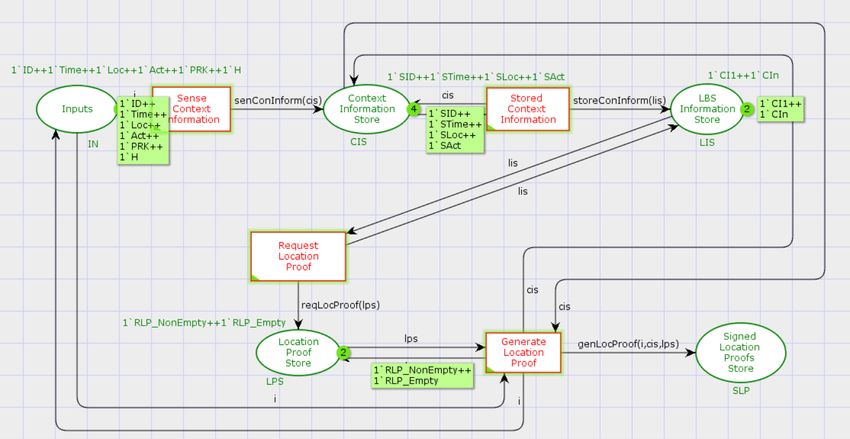
verifies that the model acts as indicated in the properties. Un-               data manipulation and generating parametric graphical mod-
like simulation and testing, formal verification thoroughly eval-              els. Furthermore, state spaces and place invariant simulation
uates the behaviour of a model. It presents a formal proof based               are utilised to validate CPN models [18].
on a complex logical description of the system. The verifica-                     CPNs improve the overall usability of Petri Nets and extend
tion approach examines all relevant states of the system model                 their applications to large-scale systems. For example, CPN
to ensure that the properties given for each state are fulfilled.              models concurrent systems using Petri Net graphical compo-
Model checker demonstrates how to achieve the failure state                    nents for process communication and synchronisation, while
of the model if any state is found to be violating the observed                ML functional programming allows for new data types and data
property [31]. The most extensively used formal verification                   value modification. Furthermore, complex networks and sys-
techniques are bounded model checking and theorem proving.                     tems can be described in the CPN language as collections of
   We first built our system as a finite-state model with specifi-             modules [35].
cations denoted by temporal logic properties to conduct formal                    The following two types of models can be built with CPNs.
verification. We then verified these models using the bounded
                                                                                 • Timed Models: Time is a key performance indicator for
model checking technique specified as an automated technique
                                                                                   concurrent systems. Timed models are used to evaluate
and analysed the results using SMT-Lib and the Z3 solver. The
                                                                                   system performance in a CPN-based simulation environ-
bounded model checking problem is shown below: For exam-
                                                                                   ment.
ple, a model checking tool accepts inputs as a finite state model
Fm and a property p to find and validate the property expressed                  • Untimed Models: Unlike timed models, untimed models
as Fm | = p.                                                                       are commonly used to verify a system’s logical or theoret-
   The solver checks the expression and returns sat (satisfiable)                  ical correctness during a simulation.
or unsat (unsatisfiable). If the outcome is sat, the property fails
                                                                                  The main objective of CPN is to define a modelling language
(i.e. Fm | = p) and the solver provides a counterexample showing
                                                                               for concurrent systems that can be scaled to industrial appli-
how the model fails. If the solution results are unsatisfactory,
                                                                               cations. In light of the preceding, several formal modelling
the property is true in Fm . To define Bounded Model Checking,
                                                                               languages, notably CPNs, have been developed to address the
we use the Kripke Structure [32].
                                                                               complexity of concurrent system designs, which can occasion-
                                                                               ally result in small, undetected errors. Furthermore, with grow-
Definition 3.1. (Bounded Model Checking) [32] Given a                          ing interest in the correctness of concurrent systems, formal
Kripke structure, M = (S, S 0 , T, L), where S denotes all states,             verification approaches have evolved into a critical component
S 0 denotes initial states,T denotes transitions, and L denotes                of developing reliable systems.
the labelling function. The problem of model checking is to de-                   The main differences between CPNs and standard Petri nets
termine the set of all states in S that satisfy f, i.e. {s ∈ S |, M, s ,       are the following: (i) Petri Net tokens have no data attached to
f} where f is a temporal logic formula expressing some desired                 them, (ii) Tokens usually are black dots in Petri Nets, but in the
specification.                                                                 CPN, tokens can be any colour (types), (iii) Tokens can be de-
                                                                               fined as a sequence of complex data types such as colour sets
3.4. Coloured Petri Nets                                                       using CPN, (iv) Despite the differences in tokens between CPNs
   Coloured Petri Nets (CP-nets) is a modelling language or                    and Petri Nets models, CPNs allow a variety of data types to be
graphical tool extensively used to describe and specify concur-                added into the model, (v) The arc inscriptions used in CPNs
rent and distributed systems and investigate their behaviour us-               are expressions, not constants, (vi) The CPN ML used a vari-
ing simulation and verification based on mathematical proper-                  ety of data types, including integers, strings, reals, Booleans,
ties [33]. Petri net is a fundamental layer upon which graphical               and the void unit, (vii) Custom data types like the product, sub-
notations for specified models are constructed. These graphi-                  range, enumeration, record, union, and the list can be created
cal notations can support control structure, concurrency, com-                 using CPN ML, (viii) CPNs make Petri Nets more practical by
munication, and synchronisation using basic modelling prim-                    introducing a programming language with a higher degree of
itives. For formal analysis, utilising CPNs provides a speci-                  abstraction, increasing their scalability, and effectiveness [36].
fication language with dynamic nature and formal semantics.                       CPNs is an array N which has nine tuples, for example N={P,
Moreover, unlike domain-specific modelling, CPN modelling                      T, A, ϕ, C, F, G, L, M0 }. The definition of each tuple is as
is more generic, allowing it to build a broad range of distributed             follows [21]:
and concurrent systems [21, 34].                                                 • P is a set comprising a fixed number of places.
   CPNs have been used in a wide range of systems, includ-
ing concurrent and distributed systems, complex data networks,                   • T is a set of transitions with a finite number, such as P and
communication protocols, business process management, sci-                         T are two different sets denoted by P ∩ T = φ.
entific workflows, embedded systems, multi-agent systems, and
                                                                                 • A representing the arcs from transition to place or place to
manufacturing processes. CP-nets can also be used with cur-
                                                                                   transition.
rent modelling languages and methods like Unified Modelling
Language (UML). UML is a functional programming language                         • ϕ representing the universal colour set consisting of all
that includes primitives for defining data types, expressing                       colours, actions, and functions.
                                                                           5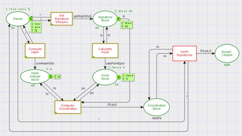
• C denotes a colour function that maps the places P and
    transitions T to defined colour set such as C : P ∪ T → ϕ.

  • F representing a node function that maps A into places and
    transitions such as A ⊆ (P × T) ∪ (T × P).

  • G ∈ g is a function that acts as a guard. Each transition t ∈
    T is associated with a guard expression g. The guard ex-
    pression’s output should be a Boolean value: true or false.

  • L is the label (or expression) associated with each arc as A,
    such that L : A → Label or Expression.                                         Figure 1: An ECDSA* Key Generation - Petri Net

  • M0 ∈ M is the CPNs start state that initiates arc and pro-          are responsible for carrying out the anticipated actions or ac-
    duces markers M0 : P → Markers.                                     tivities in the algorithms. For example, as indicated previously,
                                                                        the “Start” transition initiates the entire process. The “Gen-
   The places are depicted as circles or eclipses. Transitions          erate Domain Parameters” transition generates the domain pa-
are represented by rectangles. The acrs are depicted as directed        rameters, and the “Generate Keys” transition generates the keys
arrows. When transitions occur, the arc expression describes            based on inputs from the “Domain Parameters Store” place.
the change in each state of the CPNs. Each place contains a
collection of tokens. As compared to HLPNs, the CPN’s tokens            4.1.2. An ECDSA* Signature Generation
represent some data values tied with the place.                            The Petri net of the signature generation process in an
                                                                        ECDSA* technique consists of five working transactions and
4. Modelling and Analysis of Proposed Scheme Using High-                four places, as shown in Fig. 2.
   Level Petri Nets

   This section details the formal modelling and analysis of the
proposed scheme for detecting clone node attacks. We used
HLPNs to model our proposed scheme and the Z specification
language to specify the rules or properties that defined the be-
haviour of the underlying proposed system’s model.
   We divide our proposed scheme into parts to facilitate the
modelling process, such as an ECDSA* technique and a LPS
technique. Each part, along with its HLPN modelling, is pre-
sented separately in the sections 4.1 and 4.2. Furthermore, in
section 4.3, a set of rules consisting of syntax and semantics is                Figure 2: An ECDSA* Signature Generation - Petri Net
presented to specify the interaction behaviours of the proposed            In this Petri net, the transitions are “Start”, “Compute Co-
scheme’s components. Finally, the analysis of the modelling re-         ordinates”, “Compute Hash”, “Generate Signature Pair 1”, and
sults obtained using incidence marking and confidence intervals         “Generate Signature Pair 2”, while the places are “Inputs”, “Co-
are presented and discussed in detail in the section 4.4.               ordinates store”, “Hash Integer Store”, and “Signature Store”.
                                                                        The “Start” transition begins the ECDSA* signature generation
4.1. An ECDSA* Technique                                                process and stores all initial variables in the “Inputs” place. In
  An ECDSA* technique is divided into three HLPNs based on              contrast, the “Compute Coordinates” transition accepts the inte-
the algorithms used to generate keys, generate signatures, and          ger value from the “Inputs” place. It computes the coordinates
verify signatures.                                                      used in the signature generation pairs stored in the “Coordi-
                                                                        nates Store” place. The “Compute Hash” transition computes
4.1.1. ECDSA* Key Generation                                            the hash value of the inputs specified in the “Inputs” place, con-
   Fig. 1 illustrates the HLPN of the key generation process in         verts it to an integer value, and stores it in the “Hash Integer
the ECDSA* technique. In Petri nets, the process starts with            Store” place. The transitions “Generate Signature Pair 1” and
the “Start” transition, the initial state of any HLPN and is re-        “Generate Signature Pair 2” take inputs from the “Coordinates
sponsible for creating tokens that transit through all subsequent       Store” and “Hash Integer Store” places and generate the signa-
transitions. The terms “Inputs”, “Domain Parameters Store”              ture pair, which is then stored in the “Signature Store” place.
and “Keys Store” refer to the places or stores used to store the
preliminary data (or variables). The “Inputs” place contains the        4.1.3. An ECDSA* Signature Verification
initial data required to generate the domain parameters. The               The HLPN of the signature verification in an ECDSA*
“Domain Parameters Store” place has the domain parameter                scheme is depicted in Fig. 3.
values used during the key generation process, and the “Keys               The HLPN contains various transitions, including “Start”,
Store” place contains the public and private keys. Transitions          “Get Signature Integers”, “Calculate Hash”, “Calculate Point”,
                                                                    6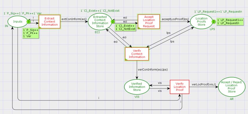
Table 1: Places, Mappings and Description of an ECDSA* Technique
                                                                             Places                        Mappings               Description
                                                                             An ECDSA* Key Generation
                                                                                                                                  Holds the standard
                                                                             ϕ (Inputs)                    P(p × E × P × n × h)
                                                                                                                                  domain parameters
                                                                                                                                  Holds the standard
                                                                             ϕ (Domain Parameters Store)   P(p × E × P × n × h)
                                                                                                                                  domain parameters
                                                                                                                                   Store the private
                                                                             ϕ (Keys Store)                P(d × Q)
                                                                                                                                   and public keys
                                                                             An ECDSA* Signature Generation
                                                                                                                                     Holds the input
                                                                             ϕ (Inputs)                    P(m × d × H × P × k)   variables used in the
                                                                                                                                  signature generation
                                                                                                                                       Stores the x
                                                                             ϕ (Coordinates Store)         P(X)
                                                                                                                                    and y coordinates
                                                                                                                                     Stores the hash
                                                                             ϕ (Hash Integer Store)        P(e)
                                                                                                                                      integer value
                                                                                                                                  Stores the signature
                                                                             ϕ (Signature Store)           P(r × s)
                                                                                                                                           pair
                                                                             An ECDSA* Signature Verification
                                                                                                                                  Holds the signature
         Figure 3: An ECDSA* Signature Verification - Petri Net              ϕ (Inputs)                    P(r × s × Q × m)
                                                                                                                                  pair and public key
                                                                                                                                  Stores the signature
                                                                             ϕ (Signature Store)           P(r × s)
“Calculate Coordinates” and “Verify Signatures”. On the other                                                                             pair
                                                                                                                                    Stores the hash
hand, the places include the “Inputs”, “Signature Store”, “Hash              ϕ (Hash Integer Store)        P(e)
                                                                                                                                     integer value
Integer Store”, “Point Store”, “Coordinates Store”, and “Ac-                 ϕ (Point Store)               P(w)
                                                                                                                                    Stores the point
                                                                                                                                         value
cept / Reject”. The signature verification procedure begins with                                                                   Stores individual
                                                                             ϕ (Coordinates Store)         P(u1 × u2 )
the “Start” transition, which stores the signature parameters and                                                                  coordinate values
                                                                                                                                         Stores
public key in the “Inputs” place. The “Get Signature Integers”               ϕ (Accept / Reject)           P(X)
                                                                                                                                   Coordinate point
transition then extracts the signature parameters and stores them
in the “Signature Store” place for later verification. The “Com-          four places: inputs, coordinates store, hash integer store, and
pute Hash” transition accepts the message as an input and con-            signature store. The inputs store contains a message that must
verts it to a hash integer, placed in the “Hash Integer Store”            be hashed and signed, the private key used to sign the signature,
place. On the other hand, the “Calculate Point” transition ac-            the hash function, a random base point, and a random value.
cepts the signature parameters from the “Signature Store” place           The coordinates store place is used to hold the values of the
and storing them in the “Point Store” place. Next, the “Com-              coordinates or points. Further, the hash integer store saves a
pute Coordinates” transition calculated the coordinates by ob-            hash integer value. Finally, the signature pairs are stored in a
taining the inputs from the “Hash Integer Store” and “Point               signature store place.
Store” places and storing them in the “Coordinates Store” place.             Finally, the ECDSA* signature verification method entails
Finally, a “Verify Signature” transition accepts the coordinates          using the following places: inputs, signature store, hash integer
from the “Coordinates Store” place and verifies whether to ac-            store, point store, coordinates store, and accept/reject store. The
cept or reject the signature decision.                                    inputs place contains signature pairs, a public key, and the mes-
   The complete HLPN of the ECDSA* technique, including                   sage to verify. A signature store place is where the signature
key generation, signature generation, and signature verification,         pairs extracted from the input places are stored. The message’s
is illustrated in Fig. 4, and the working mechanism is then de-           hash integer value is computed and saved in the hash integer
scribed in detail using a set of Z specification rules from 1-11.         store. The point value and coordinates are respectively kept in
   Table 1 specifies the places, mappings, and descriptions of            the places called point store and coordinates store. Finally, the
each place used in an ECDSA* technique. Since an ECDSA*                   accept/reject store place stores the verification decision.
technique includes several steps or actions, from key genera-                Table 2 lists the data types used in an ECDSA* scheme.
tion to signature generation and verification, we define algo-
rithms for each step. Each step associated with the algorithms            4.2. Location Proof System
specified for an ECDSA* technique defines the operations of                  The proposed clone node attack detection scheme based on a
each component, including standard domain parameters, key                 LPS is divided into three HLPNs based on the algorithms used,
generation, point coordinate generation, hash functions, signa-           such as calculating location, generating location proof, and ver-
ture generation, and signature verification, as well as their as-         ifying location proof.
sociated working flows, such as input and output. For example,
three places are utilised in the keys generation Petri net: inputs,       4.2.1. Calculate Location
domain parameter store, and keys store. The input place is used              Fig. 5 illustrates the HLPN of the location calculation for
to store the domain parameters at their initial state. The domain         the proposed location proof scheme in which the location cal-
parameters place is used to store the standard domain param-              culation process starts with the “Start” transition providing the
eters after being modified, and the keys store place is used to           initial variables to “Inputs” place to determine 2-D point space.
store the private and public keys.                                           The “Points Store” place holds the points, also known as co-
   The process of generating an ECDSA* signature comprises                ordinates on 2-D space, to determine the position of provers
                                                                      7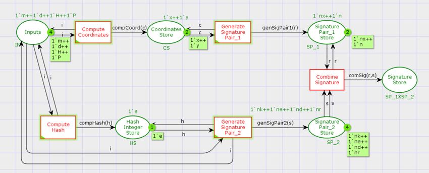
Figure 4: A Complete HLPN of an ECDSA* Technique
                                                                                               4.2.2. Generate Location Proof
            Table 2: Data Types used in an ECDSA* Scheme
   Data
                                           Description
                                                                                                  The Petri net of the generate location proof in the proposed
   Types
     p            An integer type for the representation of order of prime field
                                                                                               scheme is depicted in Fig. 6.
     E     A float type for the representation of coordinates point over the prime field
     P     An integer type for the representation of a non-zero random base point in E
                   A integer type for the representation of the ordinal value of
    n
                               P, which is normally a prime number
    h                     A float type for the representation of co-factor
    d                A byte type for the for the representation of private key
    Q                     A byte type for the representation of public key
    m              A byte type for the representation of messages to be signed
    H              A byte type for the representation of values of hash function
    k               An integer type for the representation of the random value
    X                 A float type for the representation of coordinate points
                       An integer type for the representation of hash value
     e
                                 converted from hash byte value H
     r          A float type for the representation of first pair value of signature
     s         A float type for the representation of second pair value of signature
    w                    A float type for the representation of point value
    u1              A float type for the representation of first coordinate value
    u2            A float type for the representation of second coordinate value

                                                                                                            Figure 6: Generate Location Proof- Petri Net
                                                                                                  The HLPN consists of five places and five transitions. The
                                                                                               places includes in the generate location proof HLPN are “In-
                                                                                               puts”, “Context Information Store”, “LBS Information Store”,
                                                                                               “Location Proofs Store” and “Signed Location Proofs Store”
                                                                                               while transitions are “Start”, “Sense Context Information”,
                                                                                               “Stored Context Information”, “Request Location Proof” and
                                                                                               “Generate Location Proof”. The location proof generation pro-
                  Figure 5: Calculate Location- Petri Net                                      cedure starts with the “Start” transition, which forwards and
                                                                                               store the context information, private key and hash function to
and verifiers. Based on these coordinates, the distance is calcu-                              the “Inputs” place. Following that, the “Sense Context Infor-
lated between provers and verifiers and stored in the “Proverss’                               mation” transition allows both provers and verifiers to sense the
Distance Store”. Transitions are responsible for carrying out                                  context information such as ID, time, location and activity from
the anticipated actions or activities in the algorithms. For in-                               the deployed environment and store the context information to
stance, as indicated previously, the “Start’ transition initiates                              the “Context Information Store”. Finally, the verifier performs
the entire process, the “Determine 2-D Point Space” transition                                 an additional step in the “Stored Context Information” transi-
executed the 2-D space for the provers and verifiers in the pro-                               tion, which allows the verifiers to store the sensed context in-
posed scheme, and “Calculate Distance” transition calculates                                   formation in the “LBS Information Store” place. Besides, the
the distance as a location between provers and verifiers.                                      verifiers request the provers with the location proofs performed
                                                                                           8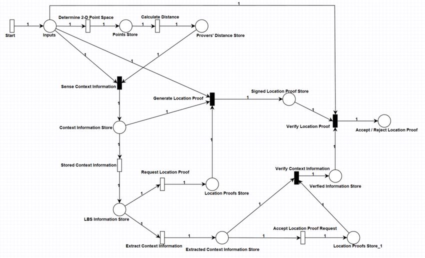
with the “Request Location Proof” transition to send the lo- The complete HLPN of the proposed clone node detection
cations proofs to verify their locations in the 2-D space and scheme on the base of LPS, including location calculation, gen-
stored in the “Location Proofs Store” place. Upon receiving erate location proof and verify location proof, is illustrated in
the requests from the verifiers at the prover side, the provers Fig. 8. The working mechanism of each Petri net is described
generated the location proofs by signing their sensed context in detail using a set of rules from 12 - 21.
information with their private key as generated in the “Gener-
ate Location Proof” transition and send and store in the “Signed Table 3: Places, Mappings and Description of location proof system
Location Proofs Store”. Places Mappings Description
Calculate Location
Holds the Coordinates of
ϕ (Inputs) P(p1 × p2 × v1 × v2 )
provers and verifiers
Holds the Coordinates of
4.2.3. Verify Location Proof ϕ (Points Store) P(p1 × p2 × v1 × v2 )
provers and verifiers
ϕ (Provers’ Distance Store) P(d) Stores the provers’ distances
The HLPN of the verifying location proofs in the proposed Generate Location Proof
Holds the context information
scheme is depicted in Fig. 7. ϕ (Inputs)
P(ID × T × Loc × Actv × KPr
×H
) variables, private keys,
and hash function
Stores the context information
ϕ (Context Information Store) P(CI)
CI
Stores the context information
ϕ (LBS Information Store) P(CI)
CI
Stores the location
ϕ (Location Proofs Store) P(Pr)
proof requests
Stores the signed
ϕ (Signed Location Proofs Store) P(P sign )
location proofs
Verify Location Proof
Holds the signatures,
ϕ (Inputs) P(P sign × KPb × V) public keys, and
list of verifiers
Stores the extracted context
ϕ (Extracted Context Information Store) P(CI)
information
ϕ (Location Proofs Store) P(Pr) Stores the location proofs
Stores the verified
ϕ (Verified Information Store) P(CI)
context information
Stores individual
ϕ (Accept / Reject Location Proofs Store) P(A × R)
coordinate values
Table 3 specifies the places, mappings, and descriptions of
each place used in LPS. The proposed scheme consists of a
mechanism detecting the clone node attack in IoT networks.
Thus, it includes several steps or actions, from location find-
ing, location proof generation and location proof verification.
Each action is associated with the algorithms specified for de-
Figure 7: Verify Location Proof- Petri Net tecting clone nodes attacks, such as deploying nodes in the 2-D
Similar to HLPN of the generate location proof, the HLPN of space, calculate the location of prover and verifier using the
verifying location proof is also consists of five places and five euclidean distance method, sensing context information from
transitions. The places includes in the HLPN are “Inputs”, “Ex- the deployed environment, storing context information on LBS,
tracted Context Information Store”, “Location Proofs Store”, generate location proof and then verify location proof. For each
“Verify Context Information” and “Verify Location Proof”. Petri net, we specified different places to store the data or vari-
The transitions includes in the HLPN are “Start”, “Extract Con- ables before or after performing the operations through transi-
text Information”, “Accept Location Proof Request”,“Verify tions.
Context Information” and “Verify Location Proof”. The pro- To calculate the Petri net, the inputs points store and provers’
cess of verifying location proof is initiated with the “Start” distance store are utilised. In inputs and point store places, the
transition, which created the initial variables such as a set of coordinates of provers and verifiers on 2-D space are stored. In
provers’ signatures and their public keys, and a set of veri- the provers’ distance store, the location of provers concerning
fiers and stored all of them in the “Inputs” place. Following verifiers in the LPS is stored.
the initiation of the verification process, the verifiers extract the Generating the location proofs comprises four places: in-
context information from the LBS by using the “Extract Con- puts, context information store, LBS information store, loca-
text Information” transition and stored this information in the tion proofs store, and signed location proofs store. The inputs
“Extracted Context Information Store” place. Upon accepting place contains the context information such as ID, time, loca-
the location proofs from the provers through the “Accept Loca- tion, activity, private key of prover and hash function. The con-
tion Proof Requests” transition, the verifiers stored the location text information store and LBS information store both saves the
proof requests to the “Location Proof Store”. When the ver- context information sensed by the verifiers. All location proofs
ifiers receive the proofs from the provers, the verifiers verify requests from the provers are stored at the location proofs store
and match the context information in the “Verify Context Infor- place. Finally, the signed location proofs are stored at the
mation” transition obtained from the provers with the context signed location proofs store place.
information from the LBS and stored in the “Verified Informa- Like the generate location proof process, five places are
tion Store”. Finally, the “Verify Location Proof” transition ver- utilised in the verify location proof process: inputs, extracted
ify the location proof signatures with the respective public key context information store, location proofs store, verified infor-
and determines the acceptance or rejection of location proof in mation store, and accept or reject location proofs store. The
the “Accept / Reject Location Proof”. inputs place is utilised to store the signed location proofs, pub-
9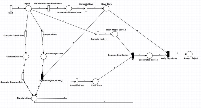
Figure 8: A Complete HLPN of the LPS
lic keys and list of verifiers. The context information extracted                        An ECDSA* process begins with the generation of crypto-
from the LBS is stored on the extracted context information                           graphic keys, both public and private. To create the keys, the
store place. All received location proofs received by the veri-                       process accepts a series of standard key parameters referred to
fiers are stored in the location proofs store place. Further, ver-                    as domain parameters, which include { p, E, P, n, h}. These
ified context information is stored at the verified information                       parameters are defined in the following order: p denotes the or-
store place. Finally, the decision about acceptance or rejection                      der in which the prime field exists, E denotes an elliptic curve
of location proofs is stored in the accept/reject location proofs                     formed over the prime field, P denotes a non-zero random base
store.                                                                                point in E, n denotes the ordinal value of P, which is typically a
   Table 4 lists the data types used in the LPS of the proposed                       prime integer, and h denotes a co-factor. The entire process
clone node attack detection scheme.                                                   of generating domain parameters is demonstrated in Rule 1,
                                                                                      namely the “Generate Domain Parameters” function.
                    Table 4: Data Types used in LPS
   Data
                                       Description
   Types
     p1      A float type for the representation of x-coordinate of a prover
     p2      A float type for the representation of y-coordinate of a prover
     v1      A float type for the representation of x-coordinate of a verifier
     v2      A float type for the representation of y-coordinate of a prover
      d        A float type for the representation of location of a prover                R(Generate Domain Parameters) = ∀d p ∈ DP, ∀gd p ∈ GDP|
     ID      An integer type for the representation of unique identification
                                                                                                                       gd p[1] := prime.field.order(dp)∧
      T       An integer type for the representation of data sensing time
    Loc       A float type for the representation of location in 2-D space                                                 gd p[2] := elliptic.curve(dp)∧
    Actv        A string type for the representation of provers’ activities
    KPr        A byte type for the representation of private key of prover
                                                                                                                              gd p[3] := base.point(dp)∧
     H               A byte type for the representation of hash value                                                      gd p[4] := ordinal.value(dp)∧
     CI        A byte type for the representation of context information
     Pr       A byte type for the representation of location proof request
                                                                                                                                gd p[5] := cofactor(dp)∧
   P sign     A byte type for the representation location proof signature              gd p[6] := Generate Domain Parameters(gd p[1], gd p[2], gd p[3],
    KPb        A byte type for the representation of public key of prover
      V             A byte type for the representation of verifiers list
                                                                                                                                        gd p[4], gd p[5])∧
      A         A string type for the representation of accepted decision             GDP = GDP ∪ {gd p[1], gd p[2], gd p[3], gd p[4], gd p[5], gd p[6]}
                                                                                           0
      R         A string type for the representation of rejected decision                                                                         (1)

4.3. Z Specification Rules                                                              The procedure for generating keys, such as public and pri-
   This section presented a set of rules consistent with the syn-                     vate keys, is described in Rule 2. Key generation procedure
tax and semantics of the Z language for specifying the inter-                         generates a pair of public and private keys for use in the signing
action behaviours of the proposed scheme’s components. As                             and verification processes. For example, the private key can be
previously stated, the proposed scheme is modelled into two                           generated by selecting a random integer d and multiplying it by
parts, each illustrated with its HLPN. The rules 1 - 11 specify                       a non-zero random base point P to get the public key Q. The
the modelling part of an ECDSA*, while rules 12 - 21 specify                          “Generate Keys” function receives the domain parameters as
the modelling part of a LPS.                                                          input and returns the private and public keys to sign and verify
                                                                                 10
signatures. sent to the verifier’s party for verification.
R(Generate Keys) = ∀dk ∈ DK, ∀gk ∈ GK|
R(Generate Signature Pair 2) = ∀k ∈ K, ∀gk ∈ GK, ∀prk ∈ PRK,
gk[1] := generate.private.key(dk)∧
∀s ∈ S , ∀S S ∈ S |
gk[2] := generate.public.key(dk)∧ (2)
ss[1] := private.key(gk[1])∧
gk[3] := Generate Keys(gk[1], gk[2])∧
ss[2] := random.integer(k[1])∧
GK 0 = GK ∪ {gk[1], gk[2], gk[3]}
ss[3] := hash.integer(s)∧
The function “Compute Coordinates” in Rule 3 defines and ss[4] := Generate Signature Pair 1(ss[1], ss[2], ss[3])∧
computes the coordinates that can be used in the signature gen- S S 0 = S S ∪ {ss[1], ss[2], ss[3], ss[4]}
eration process. This procedure begins by selecting a random (6)
integer for the k parameter. The coordinates X are then calcu- The process of signature verification begins with extracting
lated by multiplying the random number k by the random point the signatures computed in the function “Get Signature Inte-
P. gers”, such as r and s, from the signatures store generated in
the Rules 5 and 6. The procedure of determining whether the
signature values r and s are within the interval. The entire pro-
R(Compute Coordinates) = ∀gd p ∈ GDP, ∀k ∈ K, ∀c ∈ C| cedure for obtaining the signature integers is explained in Rule
c[1] := random.integer(k)∧ 7.
c[2] := base.point(gdp[3])∧
c[3] := Compute Coordinates(c[1], c[2])∧
R(Get Signature Integers) = ∀si ∈ S I, ∀sig ∈ S IG|
C 0 = C ∪ {c[1], c[2], c[3]}
(3) sig[1] := signature.integer.1(si)∧
After computing the coordinates, the function “Compute sig[2] := signature.integer.2(si)∧ (7)
Hash” acts as a hash function H, taking the message m and pro- sig[3] := Generate Signature Integers(sig[1], sig[2])∧
ducing a hash value in the form of a digest string value, which S IG0 = S IG ∪ {sig[1], sig[2], sig[3]}
is then transformed into an integer e, as shown in Rule 4.
After obtaining the signature integers for verification, the
R(Compute Hash) = ∀h ∈ H, ∀e ∈ E| hash function H computes the hash value of the message m for
e[1] := message(h)∧ comparison. Then, as with the hash creation in Rule 4, the hash
(4) value is transformed to an integer e using the function “Com-
e[2] := compute.hash(e[1])∧
pute Hash”, as computed in Rule 8.
E 0 = E ∪ {e[1], e[2]}
The Rule 5 outlines the procedure of generating signature R(Compute Hash) = ∀m ∈ M, ∀hi ∈ HI|
pair 1, which is performed by the function “Generate Signa- hi[1] := message(m)∧
ture Pair 1”. This function calculates the signature parameter r (8)
hi[2] := Compute Hash(hi[1])∧
by modifying the previously calculated x in the range of total
numbers n. HI 0 = HI ∪ {hi[1], hi[2]}
In the function “Calculate Point”, Rule 9 provides the proce-
R(Generate Signature Pair 1) = ∀r ∈ R, ∀sr ∈ S R| dure for calculating the point integer. By using the modulus of
the inverse value of the signature s, the algorithm calculated the
sr[1] := mod(r)∧
point w.
sr[2] := mod(r)∧ (5)
sr[3] := Generate Signature Pair 1 (sr[1], sr[2])∧
R(Calculate Point) = ∀sp ∈ S P, ∀cp ∈ CP|
S R0 = S R ∪ {sr[1], sr[2], sr[3]}
cp[1] := get.integer.point(sp)∧
(9)
The Rule 6 computes the function “Generate Signature Pair cp[2] := Calculate Point(cp[1])∧
2”, which outlines the process of calculating the second signa- CP0 = CP ∪ {cp[1], cp[2]}
ture pair s by taking the inverse of the k random integers and
multiplying the sum of the integer e and the private key d by Rule 10 outlines the procedure for computing coordinates by
r. Finally, the signature is stored with both the signature values calculating the integer value w. u1 and u2 are determined by
computed in Rules 5 and 6. Afterwards, the signature is then multiplying the numbers e and r by the value w, respectively,
11You can also read