Topological energy release from collision of relativistic antiferromagnetic solitons
←
→
Page content transcription
If your browser does not render page correctly, please read the page content below
Topological energy release from collision of relativistic antiferromagnetic solitons
R. M. Otxoa,1, 2, ∗ R. Rama-Eiroa,2, 3 P. E. Roy,1 G. Tatara,4 O. Chubykalo-Fesenko,5 and U. Atxitia6
1 Hitachi Cambridge Laboratory, J. J. Thomson Avenue, Cambridge CB3 0HE, United Kingdom
2 Donostia International Physics Center, 20018 San Sebastián, Spain
3 Polymers and Advanced Materials Department: Physics, Chemistry, and Technology,
University of the Basque Country, UPV/EHU, 20018 San Sebastián, Spain
4 RIKEN Center for Emergent Matter Science (CEMS) and RIKEN Cluster for
Pioneering Research (CPR), 2-1 Hirosawa, Wako, Saitama, 351-0198 Japan
5 Instituto de Ciencia de Materiales de Madrid, CSIC, Cantoblanco, 28049 Madrid, Spain
6 Dahlem Center for Complex Quantum Systems and Fachbereich Physik, Freie Universitat Berlin, 14195 Berlin, Germany
arXiv:2106.05804v1 [cond-mat.mtrl-sci] 10 Jun 2021
Magnetic solitons offer functionalities as information carriers in multiple spintronic and magnonic applica-
tions. However, their potential for nanoscale energy transport has not been revealed. Here we demonstrate
that antiferromagnetic solitons, e.g. domain walls, can uptake, transport and release energy. The key for this
functionality resides in their relativistic kinematics; their self-energy increases with velocity due to Lorentz
contraction of the soliton and their dynamics can be accelerated up to the effective speed of light of the mag-
netic medium. Furthermore, their classification in robust topological classes allows to selectively release this
energy back into the medium by colliding solitons with opposite topology. Our work uncovers important energy-
related aspects of the physics of antiferromagnetic solitons and opens up the attractive possibility for spin-based
nanoscale and ultra-fast energy transport devices.
PACS numbers:
Solutions for an efficient control of energy in nanoelectron-
ics are based on identifying the prevailing carriers and trans-
fer mechanisms of energy at relevant time and length scales.
The possibility of using spin degrees of freedom as energy
carriers is barely known. Localized magnetic textures – non-
collinear spin structures – such as domain walls (DWs), vor-
tices and skyrmions, whose stability is grounded to their non-
trivial topology [1–3], have been already discussed broadly as
information carriers [4, 5] but rarely as stationary energy stor-
ing devices [6–9]. These so-called magnetic solitons (MSs)
already play a pivotal role for the development of spin-based
applications such as processing [4, 5], sensing [10], storing
information [11] as well as radio-frequency [12] and neuro-
inspired devices [13, 14]. The simplest example of a MS is
the DW, which separates magnetic domains magnetized in op-
posite directions [15]. The exchange energy stored in the DW
can be transported by moving the DW with magnetic fields
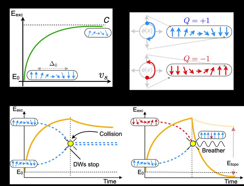
FIG. 1: (a) In antiferromagnets, domain walls (DW) can be driven
[16], spin currents [17, 18], spin waves [19–21] or even ther- up to relativistic speeds vs ≈ c, resulting in the Lorentz-contraction
mal gradients [22, 23]. While their strong stability allows for of the DW, ∆ = ∆0 γp L , and the increase of the self-energy, E(vs ) =
long-range information and energy transport, it impedes re- E0 /γL , where γL = 1 − (vs /c)2 . (b) DWs can hold two spin wind-
leasing their stored topological energy. Moreover, the only ing numbers Q = ±1, which are degenerated in energy. (c) two DWs
way to modify the energy of a DW on demand is by control- with Q = +1 and Q = +1, approaching each other in an accelerated
ling its width. However, a DW has a self-energy that is defined motion until collision. After collision DWs stop. (d) two DWs with
by intrinsic material dependent magnetic parameters, such as the opposite winding number, Q = +1 and Q = −1, approaching
each other in an accelerated motion until collision. After collision
exchange and anisotropy energy terms. Thus, means for mod-
DWs annihilate, a breather appears, and topological energy Etopo re-
ifying, transporting and extracting the free energy at magnetic leased.
textures are missing.
Our proposal relies on the unique dynamical properties of
DWs (MSs) in antiferromagnetic materials (AFM) [24–28]. 31], AFM DWs offer the possibility to transport their self-
Since they obey the relativistic kinematics, their width and energy at speeds close to the effective speed of light of the
energy strongly depend on the soliton velocity (Fig. 1a), medium, c [32] (Fig. 1a). As they preserve their shape
which results in a significant increase of magnetic energy through time, these MSs enable long-range coherent energy
in the system. Differently to DWs in ferromagnets which transport [33, 34]. Notably, since the relative orientation of
are prone to deformation at relatively low velocities [15, 29– atomic spins within the DWs can be classified into two distinct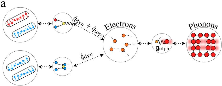
2

topological classes (Fig. 1b), here we demonstrate the possi-
bility of topologically-mediated energy release by collision of
two relativistic AFM DWs (Figs. 1c and d). For instance, for
a one dimensional (1D) DW, the topological charge is defined
as the integral over the space of the winding number density,
w (x,t) = −∇x φ (x,t). Here φ (x,t) is the in-plane angle of the
spin at location x at time t of the spin-configuration along the
1D-line of the propagation direction along the x-axis (Fig. 1b).
The total winding    number or topological charge is expressed
as: Q = π1 w (x,t) dx. Therefore, a DW in a system can ex-
            R

ist with only two distinct topological flavours, Q = ±1 (Fig.
1b). It is important to note that the homogeneous state corre-
sponds to Q0 = 0, since φ (x,t) = constant. When two DWs
of the same topology (Q1 = +1 and Q2 = +1) are driven to
collide, they cannot collapse into an homogeneous state (Fig.
1c). However, when at least two DWs with opposite topologi-
cal charge (Q1 = +1 and Q2 = −1) are forced to collide (Fig.
1d) a recombination process is accessible both from energy
and topological arguments as now Q0 = Q1 + Q2 = 0. Impor-
tantly, the topologically protected energy stored at the DWs,
Etopo is completely released.
   In AFMs, the role played by the photons in special rela-
                                                                     FIG. 2: Model simulations of the collision of two domain walls
tivity corresponds to the magnons, and c corresponds to their        (DWs) in Mn2 Au. (a,b) Spatio-temporal diagram of the dynamics
maximum group velocity. A direct consequence of special              of the process showing the DWs collision and the corresponding out-
relativity is that the MSs’ width at rest, ∆0 , contracts as its     put. (a) Two DWs with opposite topological charges result after the
velocity, vs → c,pdescribed by Lorentz factor, γL ; ∆ = γL ∆0 ,      collision in a dispersing breather; (b) Two DWs with the same topo-
where γL (vs ) = 1 − (vs /c)2 . An immediate consequence is          logical charges after the collision stop and increase their size. A
that MSs’ "kinetic" energy can also be represented in a rela-        finite x-component of the magnetization, mx , represents the position
                                                                     and extension of the DWs. Subplot (a1,b1), (a2,b2) and (a3,b3) are
tivistic form given by
                                                                     cuts of the colour map in (a) and (b) for three characteristic times
                                      E0                             t = 14, 16 and 18 ps, respectively.
                  Eexc (vs ) = p                  ,           (1)
                                   1 − (vs /c)2
where E0 corresponds to the MSs’ energy at rest (Fig. 1a).
Importantly, relativistic soliton physics is not only a theoret-     The SO-field generated by the laterally injected electrical cur-
ical construct but indirect experimental verification has been       rent acts onto the DWs through the Zeeman energy. In order
recently achieved in ferrimagnetic insulators [35]. Although         to reduce the Zeeman energy, the magnetic domain between
propagation at relativistic velocities of individual AFM DWs         the two DWs shrinks, moving both DWs towards each other.
have been investigated theoretically, their interactions with        The DWs reach their final velocities of around 42.4 km/s for
each other and the role of topology remain unexplored.               a SO-field of 60 mT with a ramping time of 10 fs in only a
   We quantify and determine the energy flow dynamics asso-          couple of picoseconds. This speed constitutes ∼98% of the
ciated to the DW motion and the collision of two high energy         maximum magnon velocity, c, for Mn2 Au. For the range of
DWs in the AFM metal Mn2 Au. This material presents a high           SO-fields investigated, the DW width reduces from 20 nm to 4
Néel temperature of circa 1500 K [36], and an efficient elec-        nm due to the Lorentz contraction. This leads to an increase of
tric control of the DW motion [28, 37, 38]. Upon passing an          a 500% of the DWs energy which can be transported (Fig. 1a
electrical current along the basal planes, the so-called inverse     and Supplementary Material). Notably, DWs are very stable
spin galvanic effect [39] produces a staggered local spin ac-        with no visible spinwave generation at these high velocities.
cumulation with opposite polarities in each sublattice which         Circa 15 ps later both DWs reach each other (Fig. 2a and b)
creates a local staggered spin-orbit (SO) field perpendicular        and collide. Two scenarios arise depending upon the topolog-
to the current direction. The dynamics of a DW induced by            ical charge carried by them, and topology conservation laws.
SO-torques can be described by the Landau-Lifshitz-Gilbert              Specifically, when Q1 = −Q2 = 1, topological charge con-
(LLG) equation for the atomistic spin dynamics (described in         servation rules allow the DWs to recombine leading to a ho-
online Supplemental Material). To follow the motion of a DW          mogeneous state Q0 = 0 (Fig. 2a). At an instant prior to
in a stripe with a long dimension parallel to x-axis, it is suffi-   the collision (t = 14 ps), both DWs are well defined (Fig.
cient to monitor the mx projection of the magnetization along        2a1), close to the moment at which they annihilate each other
the track. The initial condition in our computational model          (t = 16 ps) the two DW profiles merge (Fig. 2a2), and some
corresponds to two DWs separated by approximately 1.5 µm.            time after their disappearance as individual entities (t = 18
3

                                                                            phenomenological parameter, named Gilbert damping, which
                                                                            controls the dissipation of angular momentum in magnetic
                                                                            materials, γ is the gyromagnetic ratio and µs is the sublat-
                                                                            tice atomic magnetic moment (see SM). In layered AFM, such
                                                                            as Mn2 Au, JAFM represents the effective exchange interaction
                                                                            between layers. This sets an ultra-fast discharge timescale.
                                                                            For more details of the dynamics see also Supplementary
                                                                            videos.
                                                                                When Q1 = Q2 = 1, topological charge conservation rules
                                                                            do not allow for DWs to recombine leading to the homoge-
                                                                            neous state (Q0 = 0). Similar to the previous scenario, at an
                                                                            instant prior to the collision (t = 14 ps), both DWs are well
                                                                            defined (Fig. 2b1). After the collision, the DWs stop their rec-
                                                                            tilinear motion (conservation of momentum) (t = 16 ps) (Fig.
                                                                            2b2) hence the Lorentz factor γL ≈ 1 and as a consequence
                                                                            the DWs widen almost instantaneously, but start to oscillate
                                                                            around their final position emitting spin waves (t = 18 ps)
                                                                            (Fig. 2b3). The final state, i.e. DW widths and separation,
                                                                            however depends on energetic considerations. The system
                                                                            tries to minimize the Zeeman energy at the domain in between
                                                                            DWs by approaching them. At the same time, the repulsive
                                                                            exchange interaction becomes significant when the DWs ap-
                                                                            proach sufficiently. As a result of the competition between the
                                                                            two energies, the DWs stabilise at a certain distance between
                                                                            each other (30-90 nm, depending on the SO-field magnitude,
                                                                            i.e. the separation between DWs is much larger than their
                                                                            widths), see detailed calculations in the Supplementary Ma-
                                                                            terials. The spin wave emission is also observed, especially
                                                                            during the DWs stabilisation time.
                                                                                Still a fundamental question needs answer: how much en-
                                                                            ergy is accessible to the external environment? The mag-
                                                                            netic energy flow during the DWs collision involves the elec-
FIG. 3: (a) Stored-energy at two domain walls (DWs) with opposite           tron and lattice systems. To further quantify this process, we
topology can be transferred to the electron system by colliding them.       use a kinetic model where both local and non-local electron,
Besides q̇dyn , an additional topologically-mediated transfer mecha-        phonon and spin relaxations are included [38]. The dynam-
nisms opens up, q̇topo , when the winding of the DWs are opposite.
                                                                            ics of the electron and lattice vibrations (phonons) energies
The electron and lattice are coupled via electron-phonon coupling,
gel−ph . (b) Colour map of the spatio-temporal distribution of the rate     (expressed as their “effective quasi-equilibrium temperatures"
of heat dissipation caused by the motion of the DWs. At the collision       which can be a measurable quantity) are described by the two
(zoomed in inset) an explosion of heat occurs due to the recombina-         temperature model (TTM) [41] (Fig. 4a).
tion of DWs. Subplots (b1/c1), (b2/c2) and (b3/c3) represent the spa-           The fundamental assumption here is that the magnetic free
tial distribution of ∆Tel along the track for three characteristic times:   energy flows directly into the electron system due to metallic
14, 16 and 18 picoseconds, respectively.                                    nature of Mn2 Au (Fig. 3a).
                                                                                      dTel                      ∂ ∂ Tel
                                                                                    Cel    = −gel−ph Tel − Tph + κ       + q̇
ps), a bounded dispersing stationary breather mode is ob-                              dt                        ∂x ∂x
served (Fig. 2a3).                                                                    dTph
                                                                                  Cph      = gel−ph Tel − Tph .                             (2)
   Interestingly, a breather mode [34] is created out of the                           dt
collision between the two solitons, which is localized in the               The electron system receives an input of energy from the DW
space-time by a cone defined by the trajectory of each DW                   motion, due to the magnetic friction (spin-Peltier effect [38]),
before the collision (Fig. 2a). No spin perturbations can                   spin wave attenuation and DW collision, all of them quanti-
exist outside this cone. We observe that the past magnon-                   fied by the Rayleigh dissipation functional, q̇ = η ṡ2 , where
cone behaves like the future magnon-cone in reverse, how-                   η = µs αG /γ. Since the electron system have a much lower
ever, differently to relativity, spin perturbations lie behind the          specific heat (Cel = γel Tel ) than the lattice (Cph ), the electron
DW motion, namely outside the cone [40]. Importantly, the                   system heats up almost instantaneously at a temperature that
breather mode attenuation time is given by the exchange re-                 is larger than the lattice. The lattice heats only indirectly due
laxation time scale: 2αG γJAFM /µs ≈ 3 − 4 ps, where αG is a                to the coupling to the hot electrons via the electron-phonon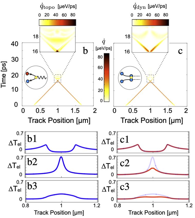
4

coupling, gel−ph (Fig. 3a). The lateral thermal electron diffu-
sion (defined by the parameter κ) is also included. We assume
room temperature parameters [38]. The details of the electron
and phonon temperature dynamics can be visualised in Sup-
plementary videos for the two topological classes presented
above.
   For a stationary moving DW, the maximum heat is released
at the DW center and the rate of its density q̇ is defined by
                                µs  vs 2
                    q̇dyn,stat = αG         .                 (3)
                                γ      ∆
We observe (Fig. 3b and c) that while the DWs move to-                FIG. 4: (a) Time evolution of the stored-energy at the DWs. Before
wards each other, their dissipation rates are equal, q̇1 = q̇2 ,      domain wall (DW) collision (yellow circle) energy increase as the
and closely follows Eq. (3). Before the collision (Figs. 3b,c,        velocity of the DWs accelerates. After collision (yellow circle), for
b1 and c1), two well-defined electron temperature peaks can           Q1 = −Q2 , a complete release of stored-energy, while for Q1 = Q2 ,
be clearly observed, corresponding to the DW positions. As            partial release of stored-energy take place. The difference of stored-
DWs approach each other closer, their shapes are affected by          energy release is defined as ∆Etopo = ∆E(Q1 , −Q1 ) − ∆E(Q1 , Q1 ).
their mutual interaction and individual topology. Spin wave           (b) The maximum (at the collision) temperature increase of the elec-
                                                                      tron system as a function of the reduced DW width, ∆/∆0 . The
generation is also observed. Remarkably, DWs positions are                                                          el = ∆T (Q , −Q ) −
                                                                      shaded area defines the topological effect ∆Ttopo      el 1       1
clearly defined until the collision, marked by two separate ∆Tel      ∆Tel (Q1 , Q1 ).
peaks.
   When Q1 = Q2 , at the instant of DWs collision, due to
the repulsion effect, their positions never merge (visible as
a white spot in the dissipated energy in the inset of Fig. 3c).       Q1 , Q2 . From our calculations, for relatively large veloci-
After the collision, DWs velocities change and the energy ex-         ties, close to c, the reduction of ∆ can reach relative values
cess redistributes between different subsystems, via spin wave        of ∆c /∆0 ≈ 0.2. For the system parameters considered here,
emission, electron-phonon coupling and lateral thermal con-           for collisions events with Q1 Q2 < 1 occurring at the highest
duction. This leads to a small energy peak (Fig. 3c2). Since          velocities (corresponding to a SO-field = 60 mT), we estimate
DWs remain well-defined separate entities during the entire           the transferred energy ∆Etopo ∼ 35 meV. In particular, we de-
dynamics, we identify this process as a purely dynamical en-          fine topological energy variation in terms of the correspond-
                                                                      ing temperatures as ∆Ttopoel = ∆T (Q , −Q ) − ∆T (Q , Q ),
ergy release, q̇dyn , the same as the spin-Peltier effect in mov-                                         el 1      1      el  1  1

ing magnetic textures [38] but for a more complex situation.          represented in Fig. 4b as a function of the DW width. We
   On the contrary, when Q1 = −Q2 , at the moment of DW               predict a measurable electron peak temperature difference be-
relativistic collision (t = 16 ps, Fig. 3b2), there is a large tem-   tween the two topologically distinct DW collision processes,
                                                                          el = 0.35 K.
                                                                      ∆Ttopo
perature boost (visible as a dark spot in the dissipated energy
in the inset of Fig. 3b) which adds to the temperature increase          To summarize, we have shown that topological magnetic
from magnetic friction, q̇dyn . Since this effect is caused by        solitons (TMSs) can be used as energy carriers. In particu-
the annihilation of TMS subject to special topological rules,         lar, antiferromagnetic domain walls (AFM DWs) can uptake,
we call this process topological energy release (q̇topo ). Soon       transport and release energy. These mechanisms are univer-
after (t = 18 ps, Fig. 3b3), we again observe attenuation of          sal for any type of AFM TMS (skyrmions, vortices, etc.). In
∆Tel at the collision site due to the energy redistribution, via      a first step, we have demonstrated that relativistic kinematics
electron-phonon coupling and lateral thermal conduction. On           of AFM TMS permits ultra-fast energy uptake. This process
longer timescale the breather disperses causing lateral spin          is based on the relativistic DW contraction. Recently, practi-
waves which finally attenuate, passing the energy to electron         cal realisation of relativistic kinematics in isolated magnetic
and phonon systems.                                                   solitons has been already demonstrated [35]. In a second step,
   The stored-energy in the DW increases as the DW accel-             thanks to the soliton nature of AF DWs, they can propagate
erates to reach their maximum velocity given by the SO-field          along the material allowing long-range energy transport. Fi-
(Fig. 4a). Interestingly, the dynamics of DW energies resem-          nally, topologically conserved collisions of two DWs which
bles that of the electric capacitor charging and discharging.         allow for annihilation processes can serve as a transfer proto-
Control of the amount of energy released into the medium is           col, to make use of the energy transported by the AF DWs in
possible using high-energy AFM DWs. Since the self-energy             a fast manner.
of the individual DWs follows the special relativity Eq. (1),            Notably, despite the intrinsic difficulties to measure mag-
one can adjust it by modifying the width of the DW at the             netic signal in AFMs, the temperature traceability unveiled
moment of the collision, ∆c (Fig. 3b). The variation of the           by our proposal opens the door to track experimentally the
self-energy of the DWs before and after the collision, ∆Ecol ,        location of TMSs and their interactions in AFMs. Our pro-
depends on both ∆c /∆0 and their relative winding numbers             posal also opens the door to ultra-fast energy management at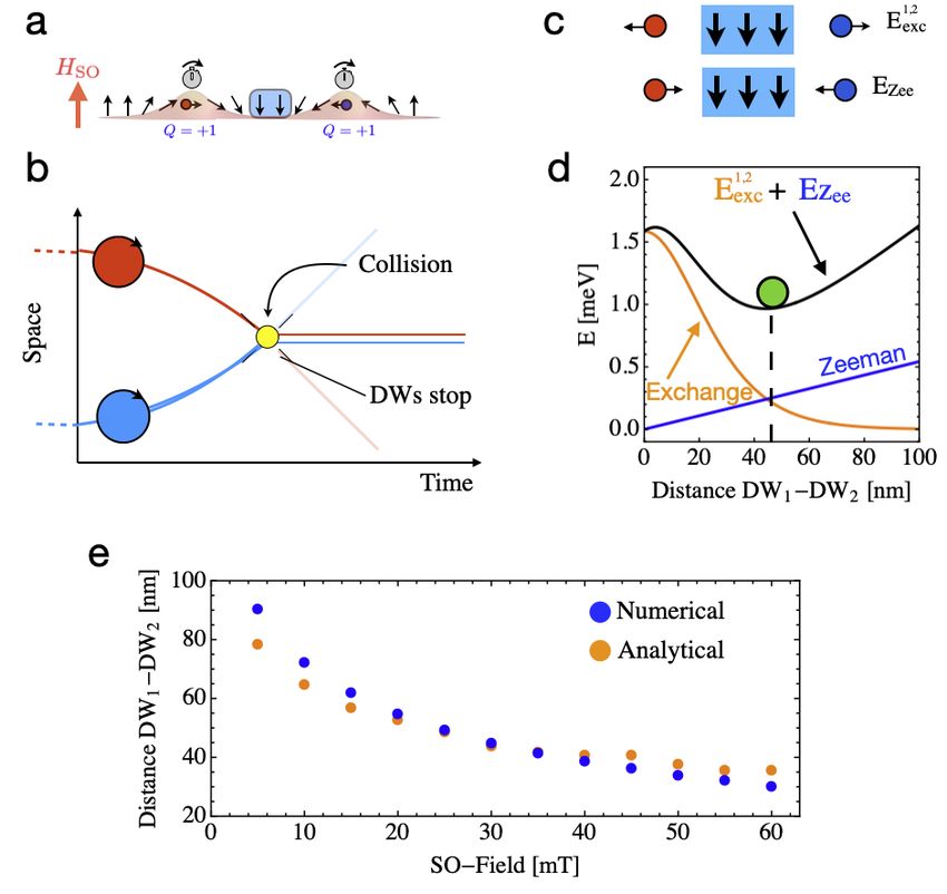
5

the nanoscale for future nanoelectronics. AFM TMS have the                    5406 (1974), URL https://doi.org/10.1063/1.2946733.
potential to become a new niche for energy transport devices             [17] J. C. Slonczewski et al., Journal of Magnetism and Magnetic
based on electron’s spin rather than on its charge.                           Materials 159, L1 (1996).
                                                                         [18] I. M. Miron, T. Moore, H. Szambolics, L. D. Buda-Prejbeanu,
   The work of R.M.O. was partially supported by the STSM                     S. Auffret, B. Rodmacq, S. Pizzini, J. Vogel, M. Bonfim,
Grants from the COST Action CA17123 Ultrafast opto-                           A. Schuhl, et al., Nature materials 10, 419 (2011).
                                                                         [19] D.-S. Han, S.-K. Kim, J.-Y. Lee, S. J. Hermsdoerfer,
magneto-electronics for non-dissipative information technol-
                                                                              H. Schultheiss, B. Leven, and B. Hillebrands, Applied Physics
ogy". R.M.O. would like to thank Andrew Ramsey for use-                       Letters 94, 112502 (2009).
ful discussions. U. A. and R.R.-E. acknowledge support from              [20] X.-g. Wang, G.-h. Guo, Y.-z. Nie, G.-f. Zhang, and Z.-x. Li,
the Deutsche Forschungsgemeinschaft through SFB/TRR 227                       Physical Review B 86, 054445 (2012).
“Ultrafast Spin Dynamics", Project A08. G.T. acknowledges                [21] P. Yan, X. Wang, and X. Wang, Physical review letters 107,
the Grant-in-Aid for Scientific Research (B) (No. 17H02929)                   177207 (2011).
from the Japan Society for the Promotion of Science. O.C-F.              [22] J. Torrejon, G. Malinowski, M. Pelloux, R. Weil, A. Thiaville,
                                                                              J. Curiale, D. Lacour, F. Montaigne, and M. Hehn, Physical
acknowledges the financial support from Spanish Ministry of
                                                                              review letters 109, 106601 (2012).
Science and Innovation under the grant PID2019-108075RB-                 [23] S. Selzer, U. Atxitia, U. Ritzmann, D. Hinzke, and U. Nowak,
C31I00/AEI/10.13039/501100011033.                                             Phys. Rev. Lett. 117, 107201 (2016), URL https://link.
                                                                              aps.org/doi/10.1103/PhysRevLett.117.107201.
                                                                         [24] E. V. Gomonay and V. M. Loktev, Low Temperature Physics
                                                                              40, 17 (2014), ISSN 1063-777X, URL https://doi.org/
                                                                              10.1063/1.4862467.
   ∗ Electronic address: ro274@cam.ac.uk                                 [25] V. Baltz, A. Manchon, M. Tsoi, T. Moriyama, T. Ono, and
 [1] A. Bogdanov and U. Rößler, Physical review letters 87, 037203            Y. Tserkovnyak, Rev. Mod. Phys. 90, 015005 (2018), URL
     (2001).                                                                  https://link.aps.org/doi/10.1103/RevModPhys.90.
 [2] U. K. Roessler, A. Bogdanov, and C. Pfleiderer, Nature 442,              015005.
     797 (2006).                                                         [26] O. Gomonay, V. Baltz, A. Brataas, and Y. Tserkovnyak, Nature
 [3] K. Litzius, J. Leliaert, P. Bassirian, D. Rodrigues, S. Kromin,          Physics 14, 213 (2018), ISSN 1745-2481, URL https://doi.
     I. Lemesh, J. Zazvorka, K.-J. Lee, J. Mulkers, N. Kerber, et al.,        org/10.1038/s41567-018-0049-4.
     Nature Electronics 3, 30 (2020).                                    [27] T. Shiino, S.-H. Oh, P. M. Haney, S.-W. Lee, G. Go, B.-G.
 [4] S. S. Parkin, M. Hayashi, and L. Thomas, Science 320, 190                Park, and K.-J. Lee, Phys. Rev. Lett. 117, 087203 (2016), URL
     (2008).                                                                  https://link.aps.org/doi/10.1103/PhysRevLett.
 [5] D. Allwood, G. Xiong, M. Cooke, C. Faulkner, D. Atkinson,                117.087203.
     N. Vernier, and R. Cowburn, Science 296, 2003 (2002).               [28] R. M. Otxoa, P. E. Roy, R. Rama-Eiroa, J. Godinho, K. Y.
 [6] T. An, V. I. Vasyuchka, K. Uchida, A. V. Chumak, K. Ya-                  Guslienko, and J. Wunderlich, Communications Physics 3, 190
     maguchi, K. Harii, J. Ohe, M. B. Jungfleisch, Y. Kajiwara,               (2020), ISSN 2399-3650, URL https://doi.org/10.1038/
     H. Adachi, et al., Nature Materials 12, 549 (2013), ISSN 1476-           s42005-020-00456-5.
     4660, URL https://doi.org/10.1038/nmat3628.                         [29] A. Mougin, M. Cormier, J. P. Adam, P. J. Metaxas, and
 [7] E. Y. Vedmedenko and D. Altwein, Phys. Rev. Lett.                        J. Ferré, EPL 78 (2007), URL https://doi.org/10.1209/
     112, 017206 (2014), URL https://link.aps.org/doi/10.                     0295-5075/78/57007.
     1103/PhysRevLett.112.017206.                                        [30] R. Hertel and C. M. Schneider, Physical review letters 97,
 [8] Y. Tserkovnyak and J. Xiao, Phys. Rev. Lett. 121,                        177202 (2006).
     127701 (2018), URL https://link.aps.org/doi/10.                     [31] G. Tatara and R. M. Otxoa de Zuazola, Phys. Rev. B
     1103/PhysRevLett.121.127701.                                             101, 224425 (2020), URL https://link.aps.org/doi/10.
 [9] D. Jones, J. Zou, S. Zhang, and Y. Tserkovnyak, Phys. Rev. B             1103/PhysRevB.101.224425.
     102, 140411 (2020), URL https://link.aps.org/doi/10.                [32] F. D. M. Haldane, Phys. Rev. Lett. 50, 1153 (1983), URL
     1103/PhysRevB.102.140411.                                                https://link.aps.org/doi/10.1103/PhysRevLett.50.
[10] D. A. Allwood, G. Xiong, C. Faulkner, D. Atkinson, D. Petit,             1153.
     and R. Cowburn, Science 309, 1688 (2005).                           [33] S. M. Mohseni, S. R. Sani, J. Persson, T. N. A.
[11] S. Fukami, T. Suzuki, K. Nagahara, N. Ohshima, Y. Ozaki,                 Nguyen, S. Chung, Y. Pogoryelov, P. K. Muduli, E. Ia-
     S. Saito, R. Nebashi, N. Sakimura, H. Honjo, K. Mori, et al., in         cocca, A. Eklund, R. K. Dumas, et al., Science 339,
     2009 Symposium on VLSI Technology (IEEE, 2009), pp. 230–                 1295 LP (2013), URL http://science.sciencemag.org/
     231.                                                                     content/339/6125/1295.abstract.
[12] V. Pribiag, I. Krivorotov, G. Fuchs, P. Braganca, O. Ozatay,        [34] R. Rajaraman, Solitons and Instantons (North-Holland, Ams-
     J. Sankey, D. Ralph, and R. Buhrman, Nature Physics 3, 498               terdam, 1982).
     (2007).                                                             [35] L. Caretta, S.-H. Oh, T. Fakhrul, D.-K. Lee, B. H. Lee, S. K.
[13] J. Grollier, D. Querlioz, and M. D. Stiles, Proceedings of the           Kim, C. A. Ross, K.-J. Lee, and G. S. D. Beach, Science 370,
     IEEE 104, 2024 (2016).                                                   1438 LP (2020), URL http://science.sciencemag.org/
[14] J. Grollier, D. Querlioz, K. Camsari, K. Everschor-Sitte,                content/370/6523/1438.abstract.
     S. Fukami, and M. D. Stiles, Nature electronics 3, 360 (2020).      [36] V. Barthem, C. Colin, H. Mayaffre, M.-H. Julien, and
[15] A. Hubert and R. Schäfer, Magnetic domains: the analysis of              D. Givord, Nature communications 4, 1 (2013).
     magnetic microstructures (Springer Science & Business Media,        [37] A. Manchon, J. Železný, I. Miron, T. Jungwirth, J. Sinova,
     2008).                                                                   A. Thiaville, K. Garello, and P. Gambardella, Reviews of Mod-
[16] N. L. Schryer and L. R. Walker, Journal of Applied Physics 45,           ern Physics 91, 35004 (2019), URL https://link.aps.org/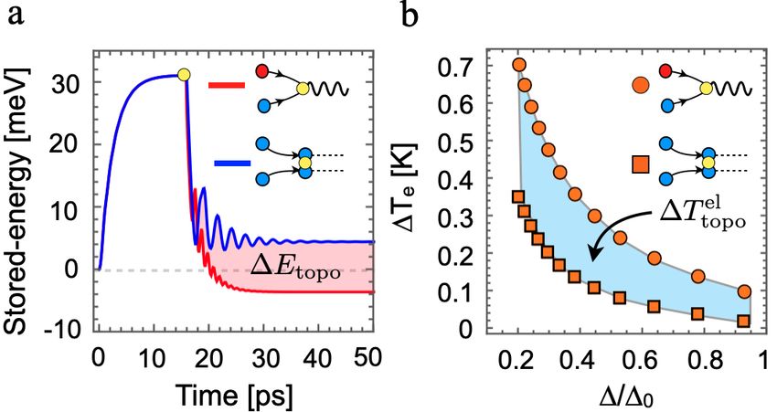
6

     doi/10.1103/RevModPhys.91.035004.
[38] R. M. Otxoa, U. Atxitia, P. E. Roy, and O. Chubykalo-Fesenko,
     Communications Physics 3, 31 (2020), ISSN 2399-3650, URL
     https://doi.org/10.1038/s42005-020-0296-4.
[39] S. Ganichev, International Journal of Modern Physics B 22, 1
     (2008).
[40] G. Tatara, C. A. Akosa, and R. M. Otxoa de Zuazola, Phys.
     Rev. Research 2, 043226 (2020), URL https://link.aps.
     org/doi/10.1103/PhysRevResearch.2.043226.
[41] M. I. Kaganov, I. M. Lifshitz, and L. V. Tanatarov, JETP 173
     (1957).
[42] P. E. Roy, R. M. Otxoa, and J. Wunderlich, Phys. Rev. B
     94, 014439 (2016), URL https://link.aps.org/doi/10.
     1103/PhysRevB.94.014439.
[43] A. B. Shick, S. Khmelevskyi, O. N. Mryasov, J. Wunderlich,
     and T. Jungwirth, Phys. Rev. B 81, 212409 (2010), URL
     https://link.aps.org/doi/10.1103/PhysRevB.81.
     212409.
[44] R. M. Otxoa, P. E. Roy, R. Rama-Eiroa, J. Godinho, K. Y. Gus-
     lienko, and J. Wunderlich, Commun. Phys. 3, 190 (2020).
[45] I. S. Gradshteyn and I. M. Ryzhik, Table of Integrals, Series,
     and Products (Academic Press, 2014).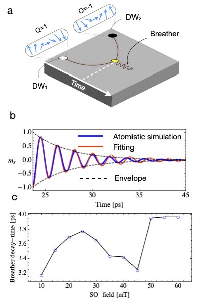
7

   Supplemental Material for "Topological energy release from collision of relativistic topological
                                            solitons"

                                                        ATOMISTIC SPIN MODEL

   We perform atomistic spin dynamics simulations for the full Mn2 Au crystal structure. A unit cell is replicated along the
x-direction 6000 times representing circa 2 µm of physical spin space. The system has periodic boundary conditions imposed
along y direction while open boundaries are considered along x and z directions. The time evolution of a unit vector spin at site
i, Si , is simulated by solving the Landau-Lifshitz-Gilbert equation:

                                              dSi
                                                  = −γ Si × Heff                eff

                                                             i − γαG Si × Si × Hi     ,                                                  (4)
                                              dt

where γ is the gyromagnetic ratio of a free electron (2.21×10⁵ m/As), αG is the Gilbert damping set here to 0.001 and Heff    i
is the effective field resulting from all of the interaction energies. The configuration energy is constituted by three exchange
interactions (two antiferromagnetic and one ferromagnetic), magneto crystalline energy contributions and the SO field. The total
energy, E is:

                                         E = −2     ∑      Ji j Si · S j − K2⊥ ∑ (Si · ẑ)2 − K2k ∑ (Si · ŷ)2 −
                                                  hi< ji                      i                   i

                               K4⊥                K4k h                           i
                                   ∑ (Si · ẑ)4 −    ∑ (Si · û1 )4 + (Si · û2 )4 − µ0 µS ∑ Si · Heff
                                                                                                   i .                                   (5)
                                2 i                2 i                                     i

The first term on the right-hand side is the exchange energy where Ji j is the exchange coefficient along the considered bonds
[38, 42]. The second and third terms are the uniaxial hard and easy anisotropies of strengths K2⊥ and K2k , respectively, while the
fourth and     terms collectively describes tetragonal anisotropy. For the in-plane part of the tetragonal anisotropy, u1 =[110]
          fifth
and u2 = 11̄0 . Finally, µ0 and µs are the magnetic permeability in vacuum and the magnetic moment, respectively. We have
used µs = 4µB [36], with µB being the Bohr magneton. The effective field is evaluated at each spin site in time using Eq. (5) as
         −1 δ E
Heff
  i = µ0 µs δ Si . The system of equations, Eq. (4) are solved by a fifth order Runge-Kutta Method. Material constants used are
summarised in the following table:

                                    −1          −1          −1
                               Ji1 kB  [K] Ji2 kB  [K] Ji3 kB  [K]       K2⊥ [J]     K2k [J] K4⊥ [J]    K4k [J]
                                  -396       -532            115     -1.303×10⁻²²    7K4k     2K4k 1.855×10⁻²⁵

     TABLE I: Literature values for material parameters relevant for modelling the spin dynamics [36, 43]. kB is Boltzmann’s constant.

                                 DYNAMICS OF THE SELF-ENERGY OF TWO DOMAIN WALLS

   In the ferromagnetic (FM) basal planes of the antiferromagnet (AFM) Mn2 Au, it is possible to stabilize 180◦ Neel-like domain
walls (DWs) due to the presence, mainly, of the uniaxial hard-axis anisotropy along the z-th spatial direction, encoded through
the K2⊥ parameter, which constrains the magnetization in the xy basal plane, and due to the action of the uniaxial easy-axis
anisotropy along the y-th spatial direction, which is represented by K2k (See previous section for more information). To describe
one-dimensional (1D) magnetic DWs, it is convenient to introduce the Walker-like symmetric rigid profile, given by

                                                                        Qi (x − Xi (t))
                                              φi (x,t) = 2 arctan exp                     ,                                   (6)
                                                                              ∆

expression which is characterized by the DW topological charge, Qi , the central position of the soliton, Xi , and its DW width,
∆ [16, 34]. We consider a system consisting of two DWs, denoted through i = 1, 2 indices, with DW topological charges and
central positions Q1,2 and X1,2 , respectively. In this case, the combined profile of the system is given by

                                                              Q1 (x − X1 (t))                    Q2 (x − X2 (t))
                      φ (x,t) = ∑ φi (x,t) = 2 arctan exp                       + 2 arctan exp                     .         (7)
                                   i                                ∆                                  ∆
8
The total exchange energy, Eexc , composed of both magnetic textures for the case of a 1D spin chain, can be expressed as
Z +∞
!2
Eexc = a20 A ∑ ∂x φi (x,t) dx, (8)
−∞ i
where A represents the effective exchange stiffness of the system, a0 is the in-plane lattice constant [44], and where ∂x expresses
the spatial derivative along the x-th spatial direction of the profile of each DW, the latter being given by
Qi x − Xi (t)
∂x φi (x,t) = sech . (9)
∆ ∆
Taking into account Eq. (9), it is possible to explicitly write the terms inside the integral of Eq. (8) as follows
!2
1 2 x − X1 (t) 2 x − X2 (t)
∑ ∂x φi (x,t) =
∆2
sech
∆
+ sech
∆
+
i
x − X1 (t) x − X2 (t)
2Q1 Q2 sech sech . (10)
∆ ∆
If this is substituted in Eq. (8), it is possible to identify different exchange-based contributions to the system. Each DW
i is therefore given by
self-energy, Eexc
a20 A +∞
2 x − Xi (t)
Z
i
Eexc = 2 sech dx. (11)
∆ −∞ ∆
1,2
An additional energy contribution comes from the exchange interaction energy between both DWs, Eexc , which is expressed as
2Q1 Q2 a20 A +∞
x − X1 (t) x − X2 (t)
Z
1,2
Eexc = sech sech dx, (12)
∆2 −∞ ∆ ∆
1 +
which allows for writing the total energy, Eexc , as the sum of the following independent exchange contributions: Eexc = Eexc
1,2
2 + E . In , we focus on the interaction term between DWs (third term on the right-hand side in Eq. (10)) and the resulting
Eexc exc
dynamics when subject to a spin-orbit (SO) field.
Analyzing the individual contributions to the exchange energy by the magnetic textures, expressed in Eq. (11), it is possible
to obtain that
i 2a20 A
Eexc = , (13)
∆
so if the self-energy of both textures is taken into account, we can see that, regardless of their topological charge Qi , both
1 + E 2 = 2E i = 4a2 A/∆, since the involved hyperbolic function is an even
contributions will be equal, giving rise to Eexc exc exc 0
i , as a function of the relativistic contraction when subject to a spin-orbit
function. The time evolution of the self-energy, Eexc
(SO) field, HSO , is shown in Suppl. Fig. 5.
CALCULATION OF THE INTERACTION ENERGY BETWEEN TWO DOMAIN WALLS
The integral given by Eq. (12), which represents the DW interaction, is more complicated than the other two terms. To solve
it, we will first use the following trigonometric relationship
cosh (ξ1 ) cosh (ξ2 ) = a + a cosh (2ξ1 ) + b sinh (2ξ1 ) , (14)
where ξi = (x − Xi (t)) /∆, and
1 X1 (t) − X2 (t)
a = cosh , (15)
2 ∆
1 X1 (t) − X2 (t)
b = sinh . (16)
2 ∆9
FIG. 5: Time dependence of the self-energy of the two antiferromagnetic domain walls (DWs) when subject to a spin-orbit field, HSO , which
ramps up from HSO = 0 to HSO = 60 mT in 10 fs, in the case of two solitons with opposite topological charges, which entails their annihilation
when they are conducted towards each other, which implies the liberation of the self-energy of both textures. The red dashed line represent
the sum of the static self-energy of the two DWs, E0 = 2Eexci (H 2
SO = 0) = 4a0 A/∆0 , where A represents the effective exchange stiffness of
the medium, a0 is the in-plane lattice constant, and where ∆0 expresses the DW width at rest, according to Eq. (13), which is taken as a
zero-reference for the time evolution of the exchange energy of the system.
The integral in Eq. (12) reduces to
2Q1 Q2 a20 A 2Q1 Q2 a20 A
Z +∞
1,2 dx
Eexc = = I, (17)
∆2 −∞ a + a cosh (2ξ1 ) + b sinh (2ξ1 ) ∆2
where the integral I can be rewritten as the following sum of terms
∆ +∞
dξ dξ
Z
I= +
2 0 a + a cosh (ξ ) + b sinh (ξ ) a + a cosh (ξ ) − b sinh (ξ )
∆
= [I (a, a, b) + I (a, a, −b)] . (18)
2
This integral has a tabulated solution [45], given by
1 a±b
I (a, a, ±b) = ± ln . (19)
b a
Thus, using the relation 2 atanh (x) = ln [(1 + x) / (1 − x)], the integral can be rewritten as
X1 (t) − X2 (t)
I = 2 (X1 (t) − X2 (t)) csch , (20)
∆
and, subsequently, Eq. (17) can be expressed as
4Q1 Q2 a20 A (X1 (t) − X2 (t))
1,2 X1 (t) − X2 (t)
Eexc = csch . (21)
∆2 ∆
Summarizing all the exchange contributions of the system, taking into account Eqs. (13) and (21), Eq. (8) takes the functional
form
4a2 A 4Q1 Q2 a20 A (X1 (t) − X2 (t))
X1 (t) − X2 (t)
Eexc = 0 + csch . (22)
∆ ∆2 ∆
As we have shown in the main text, when both DWs have opposite topological charge (Q1 + Q2 = 0), there is a continuous
transformation that permits both DWs to recombine giving rise to a uniform magnetic state. However, when Q1 + Q2 = 2 (See
Suppl. Fig. 6a and b), there exists a region between both DWs whose polarisation is antiparallel to HSO . As a consequence, the
Zeeman energy, EZee , pushes the DWs together in order to minimise the related energy (See Suppl. Fig. 6c). On the other hand,
1,2
there also exists a repulsive interaction between DW1 and DW2 due to the exchange interaction, Eexc , given by Eq. (21). This10
results into an expansion of the magnetic domain separating both DWs. Note that the central spins of each DW are antiparallel
to each other, which implies that, to minimize the exchange energy, both magnetic textures have to be as far as possible from the
other. The competition between these two forces, which leads to a stable distance among the two DWs, as shown in Suppl. Fig.
6b, can be expressed as
4Q1 Q2 a20 A (X1 − X2 )
X1 − X2
∆E = µ0 Ms a20 HSO (X1 − X2 ) + csch , (23)
∆2 ∆
where µ0 is the vacuum permeability and Ms represents the volumetric saturation magnetization [44]. Suppl. Fig. 6d, shows
the dependence of the Zeeman and exchange energies as a function of the relative distance between two DWs (DW1 and DW2 )
with same topological charge for an applied SO-field of 20 mT. As the SO-field and magnetic domain between the two DWs is
antiparallel, the minimum energy corresponds to a zero distance between the DWs. The opposite happens with the exchange
energy, the smaller is the distance between the two DWs, the larger is the exchange energy (A > 0). One can see (black dashed
line in Suppl. Fig. 6d) that when accounting for the exchange and the Zeeman energies, it appears a global minimum which
corresponds to a stable configuration distance between DW1 and DW2 . A comparison between the stable distance among the
two DWs as a function of the applied SO-field extracted from numerical simulations and Eq. (23) is shown in Suppl. Fig. 6e. It
can be observed that starting for the larger SO-field (60 mT), the stable distance increases as the SO-field is reduced, meaning
that the Zeeman force needs more extension of the magnetic domain to compensate the repulsion between the DWs.
FIG. 6: a) Sketch of two domain walls (DWs) with the same chirality Q = +1 under the action of a spin-orbit (SO) field, HSO . They move
driven by SO-field antiparallel to the central magnetic domain (blue box). b) DWs move until collision. After the collision, both DWs remain
1,2
at an equilibrium distance from each other. c) Schematic illustration of the role played by the exchange, Eexc , and the Zeeman, EZee , energies.
While the exchange energy tries to separate DW1 and DW2 , the Zeeman energy forces them to stay as close as possible. d) Zeeman (blue
line) and exchange (orange line) energies as a function of the relative distance between DW1 and DW2 for an applied SO-field of 20 mT.
e) Comparison between analytical Eq. (23) and numerically extracted stable distances between DW1 and DW2 as a function of the applied
SO-field
.11
EQUILIBRIUM DISTANCE BETWEEN DOMAIN WALLS AND RELAXATION TIME OF BREATHER MODE
The topological charge is an invariant of the system irrespective of the number of magnetic textures. As we show in Suppl.
Fig. 7a, when two domain DWs (DW1 and DW2 ) with opposite winding number collide, they recombine because the overall
topological charge, Q = Q1 + Q2 is zero. From the energetic point of view, each DW can be interpreted as an effective potential
for the other one. When the velocity at which the collision occurs is not sufficiently large, both DWs become trapped inside the
other DW effective potential leading to an oscillatory and localized spin excitation usually called breather [34]. The dampening
process as well as the frequency of the oscillation can be mapped into a damped harmonic oscillator reproducing nicely the
convoluted oscillations obtained from numerical simulations, see Suppl. Fig. 7b. For this purpose, it is necessary to introduce
the functional form of the damped harmonic oscillator, which is given by
mx = B cos (ωt − ϕ) e−dt , (24)
where B represents the amplitude of the oscillation (being the x-th magnetization component, mx , bounded between [−1, 1]), ω
represents the oscillation frequency, ϕ is the phase, and d corresponds to the characteristic decay-time for the breather.
FIG. 7: a) Schematic illustration of two domain walls (DW1 and DW2 ) with opposite topological charge (Q1 = −Q2 ) colliding at certain time
instant, t, forming a bound state known as breather. b) Time evolution of the mx component at a fixed point x0 of annihilation, extracted along
the (x0 ,t). The oscillations are well fitted by Eq. (24). c) Breather decay-time dependence with the spin-orbit field
.
Suppl. Fig. 7c illustrates the dependence of the decay time, b, as a function of the SO-field. It can be deduced that irre-
spective of the velocity at which the collision takes place, the time devoted by the spin system to release the energy stored in
each topological magnetic soliton is only dependent of the intrinsic parameters of the system such as the damping, saturation
magnetisation and configurational energy termsYou can also read