Technology Scan White Paper - Dallas Midtown Automated Transportation System Conceptual Engineering Study - North Central Texas Council of ...
←
→
Page content transcription
If your browser does not render page correctly, please read the page content below
Dallas Midtown Automated Transportation System
                                                               Conceptual Engineering Study

                                                            Technology Scan White Paper

                                                                North Central Texas Council of Governments

                                                                                                      1|0

                                                                                               May 9, 2018

Technology Scan White Paper
North Central Texas Council of Governments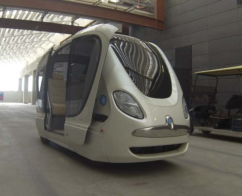
Technology Scan White Paper

Dallas Midtown Automated Transportation System Conceptual Engineering Study

Project No:                     WFXO8000
Document Title:                 Technology Scan White Paper
Document No.:                   1
Revision:                       0
Date:                           May 9, 2018
Client Name:                    North Central Texas Council of Governments
Client No:                      N/A
Project Manager:                Jeremy Wyndham
Author:                         Brian Burkhard, Craig Elliott, Stacy Learn, Marcus Ashdown
File Name:                      ATS Technology White Paper-Dallas Midtown ATS Study-05.09.2018

Jacobs Engineering Group Inc.
1999 Bryan Street, Suite 1200
Dallas, Texas 75201
United States
T +1.214.638.0145
F +1.214.638.0447
www.jacobs.com

© Copyright 2018 Jacobs Engineering Group Inc. The concepts and information contained in this document are the property of Jacobs. Use or
copying of this document in whole or in part without the written permission of Jacobs constitutes an infringement of copyright.

Limitation: This document has been prepared on behalf of, and for the exclusive use of Jacobs’ client, and is subject to, and issued in accordance with, the
provisions of the contract between Jacobs and the client. Jacobs accepts no liability or responsibility whatsoever for, or in respect of, any use of, or reliance
upon, this document by any third party.

1
Technology Scan White Paper

Contents
1.      Introduction ............................................................................................................................................... 3
1.1     History of the Modern Automated People Mover ........................................................................................ 3
2.      Automated People Mover (APM) ............................................................................................................. 5
2.1     Bombardier INNOVIA APM 200/300........................................................................................................... 6
2.2     Mitsubishi Crystal Mover ............................................................................................................................. 7
2.3     Schwager Davis UniTrak ............................................................................................................................ 8
3.      Monorail ................................................................................................................................................... 10
3.1     Bombardier INNOVIA Monorail 200/300................................................................................................... 10
3.2     Hitachi Monorail ........................................................................................................................................ 12
3.2.1   Hitachi Standard Monorail......................................................................................................................... 12
3.2.2   Hitachi Small Monorail .............................................................................................................................. 13
4.      Cable-Propelled Systems ....................................................................................................................... 14
4.1     Doppelmayr Cable Car (DCC) Cable Liner Shuttle .................................................................................. 14
4.2     Leitner-Poma Mini Metro........................................................................................................................... 16
5.      Gondolas ................................................................................................................................................. 18
5.1     Aerial Tramways ....................................................................................................................................... 19
6.      Personal Rapid Transit (PRT) ................................................................................................................ 21
6.1     2getthere ................................................................................................................................................... 22
6.2     Ultra Global ............................................................................................................................................... 23
6.3     Vectus ....................................................................................................................................................... 24
7.      Group Rapid Transit (GRT) .................................................................................................................... 26
7.1     West Virginia University Personal Rapid Transit ...................................................................................... 26
7.2     Vectus ....................................................................................................................................................... 27
8.      Automated Vehicle Shuttle .................................................................................................................... 29
8.1     EasyMile ................................................................................................................................................... 29
8.2     NAVYA ...................................................................................................................................................... 30
8.2.1   AUTONOM SHUTTLE .............................................................................................................................. 30
8.2.2   AUTONOM CAB ....................................................................................................................................... 32
8.3     Local Motors ............................................................................................................................................. 33
8.4     AV Shuttle Comparison............................................................................................................................. 34
9.      Automated Vehicle Fleet ........................................................................................................................ 35
9.1     Waymo ...................................................................................................................................................... 35
9.1.1   System Operations ................................................................................................................................... 35
9.1.2   Testing ...................................................................................................................................................... 36
10.     Future Technologies............................................................................................................................... 38

2
Technology Scan White Paper

1. Introduction
This Technology Scan White Paper is intended to provide a review of current industry usage of public
transportation vehicle capabilities. In particular, this paper puts forth transportation planning’s best practice in the
context of automation. The purpose of this white paper is to inform and enlighten stakeholders of the Dallas
Midtown area on considerations as they move forward on building the development. It is also intended to serve
as a means of outreach to engage stakeholders in the alternatives conversations to follow.

The paper reviews technologies for Automated Vehicles and Fleets as well as more traditional Automated People
Movers, Monorail, Cable Propelled Systems and Personal and Group Rapid Transit.

1.1          History of the Modern Automated People Mover

Some of the earliest modern-day Automated People Mover (APM) concepts
were developed in the 1950s when General Motors investigated driverless
vehicles on separate guideways. Later in that same decade, the New York
City Transit Authority briefly demonstrated an automated people mover
operation along 42nd Street between Times Square and Grand Central
Station. About a decade later, Westinghouse Electric Corporation
developed an APM technology called Skybus with federal funding provided
by the U.S. Department of Housing and Urban Development. Skybus
utilized transistor technology, rubber tires, and center guidebeam guidance.
The system was called the South Park Demonstration Project for the Port
Authority of Allegheny County (PAAC). It operated between 1965 and
1966, and while Pittsburgh’s urban transportation experiment did not
survive, Westinghouse further developed the Skybus technology and                           Figure 1. PAAC Skybus
implemented a later version called the C-100 at Tampa International                         Demonstration Project1
Airport 5 years later as the first airport APM.1

The construction of the Morgantown automated system in 1975 and the UMTA Downtown People Mover Program
(DPM) highlights U.S. Government interest in PRT and APM systems in the 1960s-1970s as a less expensive
alternative to other mass transit systems while promoting a more comprehensive approach to city planning. The
development of the Morgantown PRT system in West Virginia was supported by President Nixon as a USDOT
PRT Demonstration Project as well as by UMTA development grants and is still operating today.

The UMTA DPM encouraged cities to build APMs as downtown circulators as an alternative to more expensive
mass transit systems. From 1976-1977 the UMTA selected Baltimore, Cleveland, Detroit, Houston, Indianapolis,
Jacksonville, Los Angeles, Miami, Norfolk, St. Louis, and St. Paul for its DPM program. In the end, only Detroit,
Jacksonville, and Miami constructed APMs, all of which are still running today.

1
    Image: www.pghbridges.com
3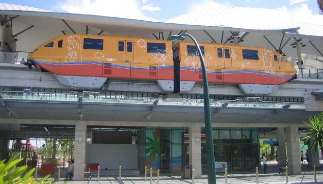
Technology Scan White Paper

Figure 2. Transportation Sec. William Coleman, right, looks at plans for Downtown People Movers in five
                            U.S. cities in 1976. (AP Photo/Harvey Georges)2

It was at this time, U.S. defense contractors diversified into transportation. Boeing supplied APM vehicles for the
Morgantown (West Virginia University) automated system in 1975. LTV Aerospace Corporation (Vought) became
an APM supplier with an extensive project at the Dallas/Fort
Worth Airport (DFW), the 13-mile AIRTRANS system. This
AIRTRANS technology served as the basis for the “Japanese
Standard APM Technology” that several Japanese APM
manufacturers licensed, including Kawasaki and Mitsubishi.

Although the U.S. government’s investment during the 1960s
and 1970s in new systems research and development was
aimed at urban 3 applications, APMs would go on to achieve
greater success at airports throughout the world. Starting with
Tampa in 1971 and continuing to the present day, APMs have
been instrumental in overcoming the problem of the growing
scale of airports in terms of their configuration and passenger
volumes. Today, there are over 100 APMs operating in airport                             Figure 3. Dallas/Fort Worth
and urban environments.                                                            International Airport AIRTRANS3

Recently, urban APMs are undergoing a resurgence in the USA. Several new systems using cable technologies
have been constructed in Las Vegas and Portland, Oregon. In addition, older APM systems are being refurbished
and/or redesigned, such as Morgantown and Jacksonville. In Dallas-Fort Worth, new construction and connections
to DART light rail in Las Colinas have increased ridership on its APM and have led to the construction of a new
station, system refurbishment, and renewed interest in system expansion.

2
    http://www.cdandrews.com/2014/08/downtown-people-movers-houstons-people.html
3
    Image: Lea+Elliott
4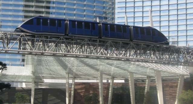
Technology Scan White Paper

2. Automated People Mover (APM)
Introduction to APMs

While classifying APMs by categories can be challenging and subject to debate as there can be overlap between
technology concepts, this report will present APMs into these generally-accepted categories: APM, Monorail,
Cable Systems, Personal Rapid Transit (PRT) and Group Rapid Transit (GRT).

Technologies that are within the APM category can be differentiated by the suspension and propulsion methods
used. Most vehicles are supported by the guideway on which they travel. This includes most monorails that
straddle the top of the guidebeam and all other guideway-supported vehicles that are supported by rubber tires,
steel wheels, pressurized air or magnetic levitation. However, suspended monorail technology hangs under the
guideway as the name implies. The means of propulsion can be divided between those that are self-propelled
with on board electric motors, cable-propelled by a continuous cable along the guideway or guideway-propelled
using Linear Induction Motors (LIMs). While there can be on-board attendants, APMs are distinguished by their
ability to be operated fully automated without drivers. The examples presented herein of automatic operation
requires an exclusive right of way. Examples of how guidance can be provided are by horizontally-mounted guide
wheels that track side-mounted guide rails, guideway-mounted center guidebeam, the guidebeam itself,
guideway-mounted center guide rail or traditional rails.

The primary application of these systems have been at major activity centers, such as airports and city centers,
but there are also numerous urban transit APM systems. These vehicles are typically supported on rubber tires,
but also use steel wheels on steel rails. They operate using automatic, driverless control permitting more cost-
effective operations on short headways to minimize waiting time for passengers.

APMs feature level boarding and operate under strict ride comfort parameters, permitting most passengers to
stand thereby increasing passenger carrying efficiency to moderately high levels. The vehicles typically have two
sets of doors on each side that allow all passengers including the mobility impaired in wheel chairs to board.
System designs are proprietary and are not interchangeable with other APM technologies.

The guideway of the APM system refers to the track or other running surface (including supporting structure) that
supports, powers, contains, and physically guides APM vehicles designed to travel exclusively on it. APMs require
a separate and exclusive guideway that can be elevated, at-grade (fenced or otherwise protected) or in tunnels.
The guideway structure itself is part of the APM facilities that is often, but not always, provided by other suppliers.

Stations are located along the guideway to allow passenger access to the APM system. The station equipment
typically includes automatic station platform edge doors and dynamic passenger information signs. The stations
also have APM equipment rooms to house command, control, and communications equipment and other APM
equipment. Boarding platforms can be side (on the outer sides of the guideway), center (in between the
guideways), or triple (both outer sides and in between the guideways).

A description of the Bombardier, Mitsubishi and Schwager Davis APM technologies and sample installations are
discussed in the following sections.

5
Technology Scan White Paper

2.1            Bombardier INNOVIA APM 200/300

Website: https://www.bombardier.com/en/transportation/products-services/rail-vehicles/automated-people-
movers.html

Bombardier Transportation, headquartered in Germany, is a division of Bombardier, Inc., a Canadian firm. They
have implemented over 30 APMs around the world of varying models. The most recent version of their self-
propelled, rubber-tired APM is the INNOVIA APM 200 and the INNOVIA APM 300. These two models are very
similar. The INNOVIA APM 300 offers increased passenger capacity, higher top speed and an aluminum car
body.

                         Figure 4. Bombardier INNOVIA APM 200, Dallas/Fort Worth Airport, TX, USA4

Both systems are guided by a center guidebeam, utilize on-board rotary electric motors and can operate as trains
of up to 6 vehicles. Power is supplied via a “third rail” on the guideway and they operate fully automated without
drivers.

Bombardier has three recent implementations of the INNOVIA APM 300 – one at the Munich Airport in Germany,
one at the Dubai Airport in the UAE and one still underway at the King Abdulaziz International Airport in Jeddah,
Saudi Arabia. The SkyLink APM at the Dallas-Fort Worth International Airport and the PHX Sky Train at the
Phoenix International Airport currently utilize Bombardier INNOVIA APM 200 technology.

Vehicle specifications for the Bombardier INNOVIA 200/300 are shown on the next page.

4
    Image: Lea+Elliott
6
Technology Scan White Paper

Table 1. Bombardier INNOVIA APM 200/300 vehicle specifications.
        Bombardier INNOVIA APM 200/300 vehicle            Value
        specifications

        Vehicle length                                    39.2 – 41.8 ft.

        Vehicle width                                     9.4 ft.

        Vehicle height                                    11.1 ft.

        Vehicle weight (unloaded)                         31,967 – 34,172 lb.

        Vehicle capacity (@ 4 passengers/m2)              100 – 103

        Maximum speed                                     37 – 50 mph

2.2            Mitsubishi Crystal Mover

Website: http://www.mhi.com/products/transport/automated_people_mover.html

Mitsubishi Heavy Industries, Ltd., headquartered in Japan, has implemented over a dozen self-propelled, rubber-
tired APMs around the world of varying models. The most recent version of their self-propelled, rubber-tired APM
is the Crystal Mover. The Crystal Mover is guided by side-mounted guide wheels running against guideway wall-
mounted guide rails. It utilizes on board rotary electric motors and can operate in trains of 1- to 6-vehicles. Power
is supplied via a “third rail” on the guideway and it operates fully automated without drivers. Miami International
Airport North Terminal will use Mitsubishi Crystal Mover APM technology.

                           Figure 5. Mitsubishi Crystal Mover, Miami Airport, FL USA5

5
    Image: Lea+Elliott
7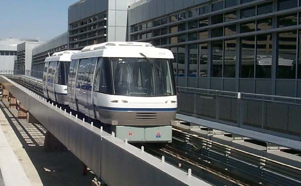
Technology Scan White Paper

Table 2. Mitsubishi Crystal Mover vehicle specifications.
        Mitsubishi Crystal Mover vehicle                  Value
        specifications

        Vehicle length                                    37.6 ft.

        Vehicle width                                     8.9 ft.

        Vehicle height                                    12.1 ft.

        Vehicle weight (unloaded)                         31,967 lb.

        Vehicle capacity                                  105

        Maximum speed                                     50 mph

2.3              Schwager Davis UniTrak

Website: https://www.schwagerdavis.com/divisions/transit/

Schwager Davis, Inc. (SDI) is a turnkey contractor in new system design, construction and installation including
system alignment, utility relocation, foundations, elevated cast in place or precast super structures, station
construction, electrical power feed, distribution and control system as well as the rolling stock.
SDI implemented a 1.4 mi. fully-automated, fully-elevated transit system for Indiana University Health (formerly
Clarian Health Partners, Inc.) and the City of Indianapolis. The system has three stations connecting three hospital
campuses. SDI has continued to operate and maintain this installation.

                     Figure 6. Schwager Davis UniTrak vehicle, IU Health, Indianapolis, IN USA6

6
    Image: SDI
8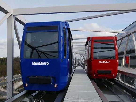
Technology Scan White Paper

The UniTrak vehicle installed at IU Health is classified as a small APM but could also be implemented as GRT
based on its car size. Each car of the 3-car train accommodates 8 seated and 19 standing passengers for a total
capacity of 27 passengers per car. Each car is fully air-conditioned and has a single 4.9 ft. wide bi-parting door
for station loading. The vehicles utilize rotary electric motors and run on rubber tires with horizontally mounted
rubber guide wheels. While the trains at IU Health operate in 3-car consists, it is possible that SDI could configure
the UniTrak vehicle in single or 2-car configurations.

SDI has identified itself as a transit supplier with the creativity and willingness to adapt its transit products to the
project-specific needs of Owners. Vehicle specifications are shown in Table 3.

Table 3. Schwager Davis UniTrak car specifications.
      Schwager Davis UniTrak car specifications              Value

      Vehicle length                                         22 ft.

      Vehicle width                                          7.9 ft.

      Vehicle height                                         9.8 ft.

      Vehicle weight (unloaded)                              15,000 lb.

      Vehicle capacity                                       27

      Maximum speed                                          28 mph

9
Technology Scan White Paper
3. Monorail
While monorail technology is typically considered a member of the APM technology category, for the purpose of
this study it will be considered as its own category due to the unique nature that the guideway is utilized. Monorails
can be considered a rail-based transportation system however the rail in this case is a concrete beam (or steel)
which the monorail vehicle “straddles.” Monorails are self-propelled with on board electric motors. While there
can be on-board attendants, monorails are distinguished by their ability to be operated fully automated without
drivers. Automatic operation requires an exclusive right of way. All other APM characteristics mentioned
previously in Section 2 also apply to monorails including stations and guideways.
Monorails offer high speed, high capacity, fully automated transportation with a major feature being the minimal
guideway requirement of only the beam(s) elevated on single piers above the roads or streets. The beams are
precast off site using purpose designed forms that maintain the quality and the consistency of the shape and
finish.
A description of the Bombardier and Hitachi monorail technologies and sample installations are discussed in the
following sections.
3.1 Bombardier INNOVIA Monorail 200/300
Website: https://www.bombardier.com/en/transportation/products-services/rail-vehicles/automated-
monorails.html
Bombardier Transportation, headquartered in Germany, is a division of Bombardier, Inc., a Canadian firm. They
have implemented four monorails in the USA of varying models with two additional installations underway. The
most recent version of their self-propelled, rubber-tired monorail is the INNOVIA Monorail 200 and the INNOVIA
Monorail 300. These two models are very similar. However, the INNOVIA Monorail 300 offers walk through
capability between cars. Both systems are supported and guided by a single concrete guidebeam, utilize on board
rotary electric motors and can operate as trains of 2- to 8-cars. Power is supplied via a “third rail” on the guidebeam
and they operate fully automated without drivers. Both systems can be paired with Bombardier’s communication-
based train control, CITYFLO 650.
Figure 7. Bombardier INNOVIA Monorail 200, Las Vegas, NV USA7
7
Image: Bombardier
10Technology Scan White Paper
Currently Bombardier has one INNOVIA Monorail 200 operating in Las Vegas. Bombardier also has two INNOVIA
Monorail 300 projects underway – one at the King Abdullah Financial District in Riyadh, Kingdom of Saudi Arabia
and the other in São Paulo, Brazil. Examples of a system implementation of the INNOVIA Monorail 300 are
provided further below.
Table 4. Bombardier INNOVIA Monorail 300 car specifications.
Bombardier INNOVIA Monorail 300 car Value
specifications
Vehicle length 38.7 – 44 ft.
Vehicle width 10.3 ft.
Vehicle height 13.5 ft.
Vehicle weight (unloaded) 29,983 lb. per car (average)
Vehicle capacity (@ 4 passengers/m2) 86-95 per car
Maximum speed 50 mph
11Technology Scan White Paper
3.2 Hitachi Monorail
Website: http://www.hitachi-rail.com/products/rolling_stock/monorail/index.html
Hitachi, Ltd., headquartered in Japan, has implemented a dozen self-propelled, rubber-tired monorails around the
world of varying models (nine are still in operation). The models are categorized as Small, Standard and Large
(the large model is not presented here as the scale of the system is inappropriate for this study). Car specifications
of the Small and Standard models can be found in Table 5 below.
All systems are self-propelled and rubber-tired. These systems are supported and guided by a single concrete
guidebeam, utilize on board rotary electric motors and can operate as trains of 2- to 6-cars. Power is supplied via
a “third rail” on the guidebeam and they can be operated fully automated without drivers or manually-operated
with drivers. Hitachi currently has no monorail systems operating in North America, but has several operating in
Japan, South Korea, China, Malaysia, and UAE.
3.2.1 Hitachi Standard Monorail
The Hitachi Standard Monorail has been implemented as both fully-automated and manually-operated systems
Hitachi has Standard Monorails operating in Tokyo, Okinawa, Dubai, and in South Korea.
Figure 8. Hitachi Palm Jumeirah Monorail, Dubai, UAE, Fully-automated without driver8
8
Image: Hitachi
12Technology Scan White Paper
3.2.2 Hitachi Small Monorail
The Hitachi Small Monorail has been implemented as a manually-operated system. This technology could also
be implemented as a fully-automated driverless system. Hitachi claims that the Small Monorail capital cost is 50%
less than a large-type monorail. Hitachi operates one of these systems in Singapore harbor.
Figure 9. Hitachi Sentosa Express Monorail, Sentosa, Singapore (Manually-operated with driver)
Table 5. Hitachi Standard and Small Monorail Car Specifications.
Car Specifications Hitachi Standard Monorail Hitachi Small Monorail
Vehicle length 48.2 ft. 24.9 - 32 ft.
Vehicle width 9.8 ft. 8.2 ft.
Vehicle height 16.7 ft. 15.3 ft.
Vehicle weight (unloaded) 52,600 – 55,000 lb. per car 28,200 - 37,800 lb.
Vehicle capacity 82 per car 43 - 49 per car
Maximum speed 37 mph 37.5 mph
13Technology Scan White Paper 4. Cable-Propelled Systems While cable-propelled technology is also considered a member of the APM technology category, for the purpose of this study it will be considered as its own category due to the unique nature that the vehicles are propelled. Cable-propelled transit systems can be categorized in two groups: 1) guideway-based and 2) aerial-based. Guideway-based systems are supported by wheels (rubber or steel) on a dedicated guideway or rails. Aerial- based systems are supported by an overhead cable or cables. Both groups are propelled by gripping (either permanently or detachable) a moving cable traveling between stations. The vehicles are passive and propulsion is provided to the cable drive wheel(s) at the station(s). For the guideway-based systems, all other APM characteristics mentioned previously in Section 2 also apply to cable-propelled systems including stations and guideways. For the aerial-based systems, there is no guideway structure as the cables are supported by towers. Stations are typically at the two end points but can be located at points in between. While the guideway-based systems can be operated fully automated without drivers, the aerial-based systems typically have attendants at the stations. Automatic operation requires an exclusive right of way. Passenger capacity per cabin can range from 4 for gondolas up to 120 for aerial tramways. Vehicle speeds can range from 13-31 mph. A description of the Doppelmayr and Leitner-Poma guideway-based and aerial-based cable technologies and sample installations are discussed in the following sections. 4.1 Doppelmayr Cable Car (DCC) Cable Liner Shuttle Website: https://www.dcc.at/ DCC Doppelmayr Cable Car GmbH & Co, headquartered in Austria, is a subsidiary of the Doppelmayr/Garaventa Group. They have implemented nine cable-propelled systems around the world. The Cable Liner Shuttle is rubber-tired with horizontal guide wheels riding inside a steel guideway. The system is cable-propelled and can operate as trains of 1- to 8-vehicles. They operate fully automated without drivers. DCC has two recent implementations of the Cable Liner Shuttle – one connecting the Oakland International Airport to the regional Bay Area Rapid Transit (BART) rail system and the other at the new Hamad International Airport in Doha, Qatar. Examples of system implementations of the Cable Liner Shuttle are provided further below. 14
Technology Scan White Paper

                         Figure 10. Doppelmayr Cable Liner Shuttle, CityCenter, Las Vegas, NV USA9

Table 6. Doppelmayr Cable Car (DCC) Cable Liner Shuttle vehicle specifications.
        Doppelmayr Cable Car (DCC) Cable Liner                     Value
        Shuttle vehicle specifications

        Vehicle length (1 car)                                     19.7 ft.

        Vehicle width                                              9.8 ft.

        Vehicle height                                             11.3 ft.

        Vehicle weight (unloaded)                                  11,023 lb.

        Vehicle capacity (1 car @ 4 passengers/m2)                 56

        Maximum speed                                              31 mph

9
    Image: Lea+Elliott
15
Technology Scan White Paper
4.2 Leitner-Poma Mini Metro
Website: http://en.minimetro.com/Home
Leitner-Poma of America is based in Grand Junction, Colorado. It is the North American subsidiary of French-
based Poma, which is owned by the Italian company Leitner Technologies, part of the Leitner Group. They
currently have approximately 20 cable-propelled systems and funiculars implemented around the world. The Mini
Metro can be rubber-tired, steel-wheeled or air-levitated (Hovair®). The system is cable-propelled and can operate
as trains of 1- to 4-vehicles. They operate fully automated without drivers. Leitner-Poma systems can currently
be found in operation at airports in Minneapolis-St. Paul, Detroit, Zurich, and Cairo,
Figure 11. Leitner-Poma (formerly Poma Otis) Mini Metro utilizing steel wheels/steel rail guidance,
Minneapolis-St. Paul Airport, MN USA10
Table 7. Leitner-Poma Mini Metro standard vehicle specifications.
Leitner-Poma Mini Metro vehicle Value
specifications
Vehicle length (1 car) 48.9 ft.
Vehicle width 9.4 ft.
Vehicle height 12.7 – 13.5 ft.
Vehicle weight (unloaded) 33,069 – 35,274 lb.
Vehicle capacity (1 car @ 4 passengers/m2) 66 – 70
Maximum speed 27 mph
10
Image: Lea+Elliott
16Technology Scan White Paper
The Mini Metro system is also available in a smaller cab configuration. Leitner-Poma currently has one system,
called Squaire Metro, operating at Frankfurt International Airport.
Figure 12. Leitner-Poma Mini Metro small vehicle on The Squaire metro, Frankfurt Airport, Germany11
Table 8. Leitner-Poma Mini Metro small vehicle specifications.
Leitner-Poma Mini Metro small vehicle Value
specifications
Vehicle length (1 car) 18.1 ft.
Vehicle width 6.9 ft.
Vehicle height 9.5 ft.
Vehicle weight (unloaded) 7,716 lb.
Vehicle capacity (1 car @ 4 passengers/m2) 33
Maximum speed 16 mph
11
Image: Leitner-Poma
17Technology Scan White Paper
5. Gondolas
Website; https://www.doppelmayr.com/en/products/
Website: http://leitner-poma.com/products/
In Gondola systems, cabins are propelled and supported by the same cable which is suspended from poles or
towers. The cabins are small and typically carry 4-15 passengers per cabin. Gondola cabins can also be
suspended by two or three closely-spaced cables. Cabins loop around the system. At the end stations, cabins
are detached from the cable and are mechanically pulled around a semicircle. Rubber wheels accelerate and
decelerate the cabins without stopping the cable drive. This reorientation at end stations does not interrupt the
traveling operation of the other cabins.
One area of concern regarding Gondolas is that their aerial location and suspended cable alignment make them
more susceptible to operational disruptions associated with high winds. However, this does not preclude using
gondolas in areas of high winds, as many mountainous regions have gondola systems. Nevertheless, system
design for gondolas, and other suspended cable-based systems, must take into consideration the environmental
conditions of the location where it operates to ensure safe operation year-round against wind.
Doppelmayr/Garaventa and Leitner-Poma both offer Gondola systems. Examples of urban gondolas can be found
throughout the world, including, Barcelona, Caracas (Venezuela), Hong Kong, La Paz (Bolivia), London, Medellin
(Columbia), Singapore, and Tlemcen (Algeria). Disney recently announced a new gondola system as part of its
new park expansion in Florida.
Figure 13. Doppelmayr/Garaventa gondola12
12
Image: Doppelmayr/Garaventa
18Technology Scan White Paper
Figure 14. Leitner-Poma gondola, Barcelona, Spain13
Table 9. Gondola system specifications
Gondola system specifications Value
Vehicle capacity (1 cabin) 4 - 15
Average Grade 20 – 35%
Maximum speed 13 mph
Minimum horizontal curve radius n/a
5.1 Aerial Tramways
Website: https://www.doppelmayr.com/en/products/
Website: http://leitner-poma.com/products/
The basic Aerial Tramway configuration has at least two cables, with one or more fixed cables providing support
and guidance while the haul rope propels the vehicle. All cables are suspended by poles or towers. Aerial
Tramways have cabins bigger than gondolas and provide a high capacity of passenger movement. In many cities,
Aerial Tramways are part of the transit infrastructure. Vehicle capacities range between approximately 30 and 120
passengers per cabin.
Doppelmayr/Garaventa and Leitner-Poma both offer Aerial Tramway systems in two configurations, as a jig-back
(reversible) system or as a single loop operation similar to gondola systems. In a jig-back system, the haul cable
propels the vehicles up and down without any impact to other vehicles. In the second configuration, a set of carriers
move in a single path of travel.
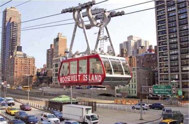
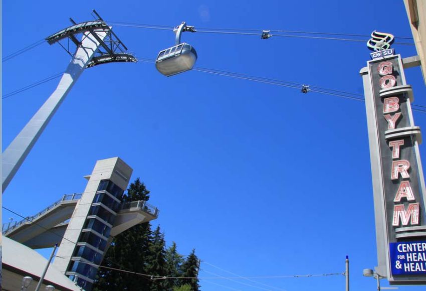
There are currently four operating Aerial Tramways operating in urban areas in the United States. The Roosevelt
Island Aerial Tramway in New York City (opened in 1976), the Portland Aerial Tram (2007), the Palm Spring Aerial
Tramway (1963), and the Mount Roberts Tramway in Juneau, Alaska (1996). Note that the latter two are
considered more like tourist attractions, however they do operate within their respective urban areas.
13
Image: Leitner-Poma
19Technology Scan White Paper
Figure 15: Portland Aerial Tram, Portland, Oregon, USA14
Figure 16. Leitner-Poma Aerial Tramway, Roosevelt Island, New York, NY USA15
Table 10. Aerial Tramway system specifications
Aerial Tramway system specifications Value
Vehicle capacity (1 cabin) 30 - 120
Average Grade 25 – 50%
Maximum speed 13 – 27 mph
Minimum horizontal curve radius n/a
14
Image: www.gobytram.com
15
Image: Leitner-Poma
20Technology Scan White Paper
6. Personal Rapid Transit (PRT)
Personal Rapid Transit (PRT) is an automated transportation technology that uses small vehicles operating at
very short headways providing non-stop, origin-to-destination travel to a selected destination. The non-stop, point-
to-point routing is accomplished by using small, off-line stations connected by a network of guideway and
sophisticated automated vehicle control hardware and software. The goal of PRT is to provide an experience
equivalent to a private automobile or taxi.
Characteristics of PRT:
PRT systems utilize small vehicles (two to six passengers) that are designed to operate directly between
origin and destination stations in a network configuration.
Some vehicles have limitations: height for entry and exit requiring riders to sit in the vehicles and the lack
of capacity for larger groups traveling together.
The PRT system including its stations and vehicles are designed to accommodate the mobility impaired,
including those in a wheelchair.
Speeds are expected to be in the 20 to 30 mph range and may vary depending on guideway configuration.
PRT systems are powered by batteries, which are recharged while the vehicles are dwelling at the
stations. Other PRT Systems use a third rail to receive electric power.
PRT propulsion can also range from conventional electric rotary motors to Linear Induction Motors (LIM)
for propulsion.
Since PRTs are automated they require a separate and exclusive guideway that is usually elevated.
However, like Automated People Movers (APMs), PRTs can be at-grade with fencing/barriers protecting
their right of way or can be located in tunnels.
The use of PRT Systems is designed to be straightforward. By pushing a button on equipment either on the
platform or on the vehicle (depending on PRT supplier), a passenger indicates to the control system his desired
destination. The desired destination information is sent electronically to the control system, which instructs the
vehicle to take the passenger to the desired location by means of the shortest non-stop route. In addition to
providing vehicles with directional instructions, Central Control also controls empty vehicle management and
ensures there is no interaction between vehicles.
The PRT system off-line stations require sufficiently long exit ramps and entry ramps leading to and from the main
guideway to the vehicle berths. The preference is that the ramp’s geometry will allow the vehicle to remain at
guideway speed until it exits the main guideway so as to not affect main guideway flow. Station design and
passenger flow management are critical to the success of a PRT system and various station configurations could
be designed to allow for location and ridership requirements. Typically, stations are configured with in-line berths,
parallel off-line berths or off-line with saw-tooth berths.
Some suppliers state system capacities of several thousand passengers per hour per lane based on vehicles
operating on very close headways (approximately 2-3 seconds).
Currently, there are three suppliers who have systems in passenger service: Ultra Global at London Heathrow
Airport, 2getthere in Masdar City, Abu Dhabi, UAE, and Vectus in Suncheon Bay, South Korea. A description of
the Ultra Global, 2getthere, and Vectus PRT technologies and their initial installations are discussed in the
following sections.
21Technology Scan White Paper
6.1 2getthere
Website: https://www.2getthere.eu/
2getthere, a Dutch company, is currently operating a 0.75 mi round trip PRT line in Masdar City in Abu Dhabi,
UAE, with two stations connecting the Masdar Institute of Science and Technology (MIST) to a parking facility.
This system is a pilot program for an expanded network, though the original extensive network plan has been
scaled back.
This system utilizes an open passive guideway with all propulsion and switching functions accomplished on board
the rubber-tired vehicle. Vehicles are guided by on-board maps and error correction is provided by magnets
embedded at 13 ft. intervals along the guideway. The single lane guideway requires a minimum width of 5.9 ft.
and needs no guideway edges or curbs. Vehicle mounted sensors detect obstructions and adjust braking and
propulsion for collision avoidance. It seats four adults and two children in forward and rear seats facing the center
of the car. The cars are fully air conditioned. Figure 17 below depicts the mainline curbless lanes of the Masdar
system and a 2getthere vehicle. Vehicle specifications are shown in the Table 11.
Figure 17. Masdar City PRT vehicle exterior16
16
Image: Lea+Elliott
22Technology Scan White Paper
Table 11. 2getthere vehicle specifications.
2getthere vehicle specifications Value
Vehicle length 12.8 ft.
Vehicle width 4.9 ft.
Vehicle height 6.6 ft.
Vehicle weight (unloaded) 3086 lb.
Vehicle capacity 4 adults + 2 children
Maximum speed 25 mph
6.2 Ultra Global
Website: http://www.ultraglobalprt.com/
Ultra Global, a United Kingdom (UK) company, has installed a starter system connecting a parking lot (with two
stations) with a single station at Terminal 5 at London Heathrow Airport (LHR). Opened in 2011, this initial
alignment is more linear or "line-haul" in its configuration than what is typically envisioned for PRT, but it could
develop into more of a grid network under its planned expansion.
The T5 Car Park has two PRT stations, Station A and Station B, with station boarding areas in a “saw tooth”
configuration and the interface where a passenger will select his/her destination.
The Ultra Global PRT system utilizes an open passive guideway with all propulsion and switching functions
accomplished on board the rubber-tired vehicle. Optical sensors on board the vehicles sense the guideway edge
curbs and provide feedback for vehicle steering and switching (lane changes). The single lane guideway is
estimated to be 7.2 ft. at its widest point, which is at curves. The vehicle seats four adult passengers, two forward-
facing and two rear-facing, all facing the center of the car. Vehicle specifications are shown in the table below.
It has been reported that Ultra Global has licensed its technology to Ultra Fairwood based in Singapore and has
announced plans for a project in Ajman City in the United Arab Emirates (UAE).
23Technology Scan White Paper
Figure 18. Ultra Global pod on guideway, Heathrow Airport, London, UK17
Table 12. Ultra Global vehicle specifications.
Ultra Global vehicle specifications Value
Vehicle length 12.1 ft.
Vehicle width 4.9 ft.
Vehicle height 5.9 ft.
Vehicle weight (unloaded) 1808 lb.
Vehicle capacity 4
Maximum speed 25 mph
6.3 Vectus
Website: http://www.vectusprt.com/EN/
The Vectus system is rail-running and guided and can be installed on a concrete or steel structure, or at-grade.
The track is passive and all switching is done on board the vehicle with a mechanical switch. Guidance is provided
through guide rails, and guide wheels ensure that the vehicles are mechanically “locked” on the guideway.
Propulsion can be provided by the vehicle using rotary motors or guideway power using Linear Induction Motors
(LIMs). The vehicle seats four adult passengers in forward and rear seats facing the center of the car. Multiple
station configurations can be supported including in-line, series, or parallel off-line berths.
17
Image: Lea+Elliott
24Technology Scan White Paper
Vectus, a UK/South Korean company, constructed a 2.8 mi. PRT system at the Suncheon Bay coastal wetlands
area in South Korea in April 2014.
Figure 19. Suncheon Bay PRT vehicle and guideway, Republic of Korea18
Table 13. Vectus vehicle specifications.
Vectus PRT vehicle specifications Value
Vehicle length 12.1 ft.
Vehicle width 6.9 ft.
Vehicle height 8.2 ft.
Vehicle weight (unloaded) 3307 lb.
Vehicle capacity 6-8
Maximum speed 43 mph
18
Image: Vectus
25Technology Scan White Paper 7. Group Rapid Transit (GRT) Group Rapid Transit (GRT) is similar to Personal Rapid Transit but with higher-occupancy vehicles and grouping of passengers with either the same destination or potentially different origin-destination pairs, depending on the GRT’s control system and vehicle assignment algorithm. In this respect, GRT can be seen as a direct-service or “typical” horizontal elevator. Such systems may have fewer direct-to-destination trips than single-destination PRT but still have fewer average stops than conventional transit, acting more as an automated share taxi system than a private cab system. Such a system may have advantages over low-capacity PRT in some applications, such as where higher passenger density is required or advantageous. It is also conceivable for a GRT system to have a range of vehicle sizes to accommodate different passenger load requirements, for example at different times of day or on routes with less or more average traffic. Such a system may constitute an "optimal" surface transportation routing solution in terms of balancing trip time and convenience with resource efficiency. GRT has principally been proposed as a corridor service, where it can potentially provide a travel time improvement over conventional rail or bus and can also interface with PRT systems. However, GRT's potential grouping of passengers makes it much less attractive in applications with lower passenger density or where few origin-destination pairs are shared among passengers. All other PRT characteristics related to stations and guideways mentioned previously in Section 6 also apply to GRT. 7.1 West Virginia University Personal Rapid Transit Website: https://transportation.wvu.edu/prt The West Virginia University Personal Rapid Transit System in Morgantown, WV is an automated people mover system that provides non-stop origin to destination travel between the separated campuses of West Virginia University and the Central Business District. The system consists of a fleet of 71 electrically-powered, rubber- tired, passenger-carrying vehicles (8-seated and 13-standing), operating on a dedicated guideway network at close headways (minimum 15 seconds). Since 1975, the system has provided and continues to provide a safe, comfortable, low polluting reliable means of transportation. The system consists of 8.2 mi of guideway and five passenger stations. Although called a PRT, many feel that this system is better labeled Group Rapid Transit (GRT) because these vehicles can carry up to 21 passengers. This technology was originally supplied by Boeing and is not currently commercially available. 26
Technology Scan White Paper

                                                Figure 20. WVU PRT vehicle and station19

Table 14. Technical specifications of Morgantown PRT vehicle

         Morgantown PRT vehicle specifications20                      Value

         Vehicle length                                               15.5 ft.
         Vehicle width                                                6.7 ft.
         Vehicle height                                               8.8 ft.
         Vehicle weight (unloaded)                                    8750 lb.
         Vehicle capacity                                             21 (8 seated)
         Maximum speed                                                30 mph

7.2            Vectus

Website: http://www.vectusprt.com/EN/

Vectus has announced plans for a GRT vehicle which will be longer and taller yet will operate on the same
guideway as the PRT vehicle. The larger vehicles are designed to accommodate standees as well as seated
passengers. The door spacing of the larger vehicles matches the door spacing of two adjacent PRT vehicles
stopped in a station. This feature allows the GRT vehicles to share the same station infrastructure with the PRT
vehicles. It is anticipated that the Vectus PRT and GRT vehicles will be able to operate simultaneously on the
same network.

The Vectus system is rail-running, rail-guided and can be installed on a concrete or steel structure, or at-grade.
The track is passive and all switching is done on board the vehicle with a mechanical switch. Guidance is provided
19
     Image: Lea+Elliott
20
     https://onlinelibrary.wiley.com/doi/pdf/10.1002/atr.5670250303
27
Technology Scan White Paper
through guide rails, and guide wheels ensure that the vehicles are mechanically “locked” on the guideway.
Propulsion can be provided by the vehicle using rotary motors or guideway power using Linear Induction Motors
(LIMs). The larger Group Rapid Transit (GRT) vehicle is planned to accommodate seated and standing
passengers, from 20 to 60 total, to be determined. A prototype vehicle for testing purposes is planned as part of
Vectus’ ongoing R&D program.
Figure 21. Vectus Group Rapid Transit (GRT) vehicle21
Table 65. Vectus GRT vehicle specifications.
Vectus GRT vehicle specifications Value
Vehicle length Not available
Vehicle width 6.9 ft.
Vehicle height In development
Vehicle weight (unloaded) In development
Vehicle capacity 20-60 (TBD)
Maximum speed 43 mph
21
Image: Vectus
28Technology Scan White Paper
8. Automated Vehicle Shuttle
Automated vehicles (AV) are vehicles used to move passengers or freight with a level of automation. They are
classified into six different levels of automation, as defined by the Society of Automotive Engineers (SAE). The
first three levels of automation (Levels 0-3) require a human driver to monitor the environment, while the last three
levels (Levels 4-6) allow an automated system to perform driving tasks. This paper introduces existing Shared
Automated Vehicles (SAV), which are level 4 and higher. These vehicles aim to transform transportation by
significantly improving safety and mobility, improving the efficiency of rides on demand, reducing carbon footprints
of cities, and solving the public transportation problem of the first and last mile connectivity.
Automated people movers are considered AV systems that are already in operation today, primarily for use in
controlled, fixed-guideway systems as described in previous sections.22 SAVs, such as AV shuttles and fleets, are
being deployed for use in a less fixed, nonetheless still contained, environment (i.e., public roadways). AV shuttles
are small, electric passenger buses that are equipped with SAE Level 5 23 (full automation) control. While all
automated shuttle service pilots are in the initial testing phase, some pilots are offering rides to the public. These
pilots are testing the feasibility of automated vehicle technology for public transit and user acceptance. EasyMile,
NAVYA, and Local Motors are three major manufacturers of low-speed automated shuttles.
8.1 EasyMile
Website: http://www.easymile.com/
EasyMile, headquartered in France, is a joint venture between vehicle manufacturer Ligier Group and Robosoft,
a high tech company specializing in robotics24 and autonomous vehicle technology. The venture has provided its
electric AV model “EZ10” for the CityMobil2 program, a multi-stakeholder project co-funded by the European Union
(EU). The goal of the CityMobil2 project is to set up a pilot platform for automated road transport systems and
study the technical, financial, cultural, and behavioral aspects of Shared Autonomous Vehicle (SAV) systems25.
The objective of CityMobil2 is to deliver:
An automated road transport service running for at least six months at five sites across Europe
Guidelines to design and implement an automated transport system
Improved understand of the interaction between automated vehicles and other road users
A legal framework proposal for certifying automated road transport systems in Europe
Showcases at numerous sites across Europe
Technical specifications for interoperable automated road transport systems, including a communications
architecture26
Outside of the CityMobil2 project, the EZ10 shuttle has been deployed in 20 countries across Asia-Pacific, Middle-
East, North America, and Europe. In 2015, EasyMile and GoMentum station – a testing ground for connected and
automated vehicles in Concord, California – announced their partnership to launch the first fleet of EZ10 vehicles
in Northern California.27 The shuttles arrived at GoMentum Station in September 2016, and the pilot demonstration
project with the Contra Costa Transportation Authority marks the first time EasyMile shuttles will be utilized in the
United States28. The EZ10 is the first fully self-driving vehicle to be approved for public roads trials in California29.
22
https://www.itf-oecd.org/sites/default/files/docs/shared-automated-vehicles-business-models.pdf
23
https://web.archive.org/web/20170903105244/https://www.sae.org/misc/pdfs/automated_driving.pdf
24
http://gomentumstation.net/wp-content/uploads/2015/10/Press-Release-Easymile-Gomentum-Station-Announce-Exclusive-Agreement-October-5-
2015-1.pdf
25
http://www.citymobil2.eu/en/About-CityMobil2/Overview/
26
http://www.citymobil2.eu/en/About-CityMobil2/Outputs-deliverables/
27
http://gomentumstation.net/easymile-and-gomentum-station-announce-exclusive-agreement/
28
http://www.ccta.net/about/download/GoMentum%20Station%20and%20BestMile%20Announce%20Partnership.pdf
29
http://easymile.com
29Technology Scan White Paper
Figure 22. EasyMile’s EZ10 driverless shuttle.30
Table 16. Technical specifications of EasyMile’s EZ10
EasyMile’s EZ10 driverless shuttle vehicle
Value
specifications31
Vehicle length 12.9 ft.
Vehicle width 6.5 ft.
Vehicle height 9 ft.
Vehicle weight (loaded) 1270 lb.
Vehicle capacity 12 (6 seated)
Maximum speed 25 mph
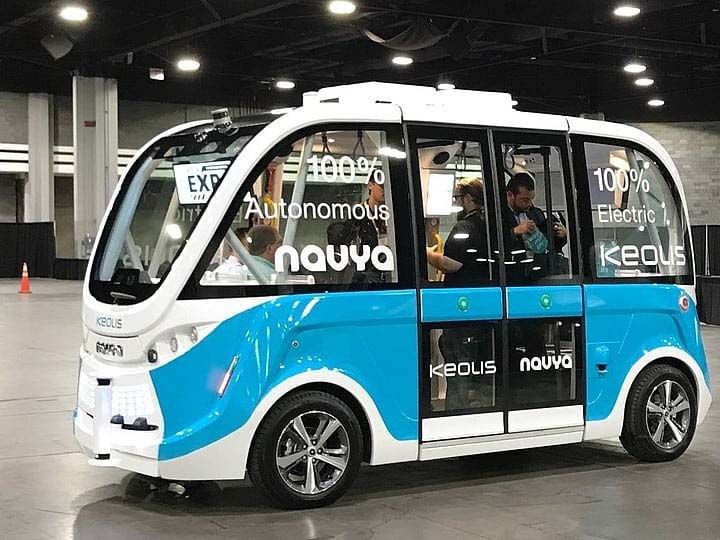
8.2 NAVYA
8.2.1 AUTONOM SHUTTLE
Website: https://navya.tech/en/autonom-en/autonom-shuttle/
NAVYA, headquartered in France, developed AUTONOM SHUTTLE as a driverless, electric shuttle service. In
2016, NAVYA delivered two AUTONOM SHUTTLEs known as ARMA for use in a two-year demonstration
30
http://www.easymile.com/#Newsroom
31
https://www.nctr.usf.edu/wp-content/uploads/2016/04/Evaluation-of-Automated-Vehicle-Technology-for-Transit-2016-Update-UPDATED-FINAL.pdf
30Technology Scan White Paper
launched in the city of Sion, Switzerland32. BestMile, a Swiss start-up, provides the software for fleet
management, allowing the remote control of the vehicles and optimization of driverless vehicle fleets33. The two
AUTONOM SHUTTLES provided shuttle service that was the first test of an autonomous passenger service, and
is also free and open to the public. As of January 2018, NAVYA has 65 vehicles deployed worldwide, in cities
and on private sites in Europe, the United States, Asia, and the Pacific. NAVYA’s AUTONOM shuttle is shown in
Figure 23. Table 17 presents the technical specifications of NAVYA’s AUTONOM SHUTTLE.
Figure 23. NAVYA’s AUTONOM SHUTTLE on demo.34
Table 77. Technical specifications of NAVYA’s AUTONOM SHUTTLE.35
NAVYA's AUTONOM SHUTTLE vehicle
Value
specifications
Vehicle length 15.6 ft.
Vehicle width 6.9 ft.
Vehicle height 8.7 ft.
Vehicle weight (unloaded) 5291 lb.
Vehicle capacity 15
Maximum speed 28 mph
In 2017, NAVYA brought the first AUTNOM SHUTTLE to the United States at the University of Michigan’s (Mcity)
Mobility Transformation Center (MTC) in Ann Arbor, Michigan. Mcity will study how passengers react, track
ridership and usage patterns, and survey users to gauge rider acceptance36. This data will help improve the safety
and operations of the vehicles.
32
https://navya.tech/en/carpostal-and-the-city-of-sion-extend-the-navya-shuttle-experimentation/
33
https://bestmile.com/2015/09/30/bestmile-teams-up-with-navya/
34
https://navya.tech/en/navya-presented-its-autonomous-shuttle-on-demo-at-the-apta-expo/
35
http://navya.tech/en/shuttle-configurator/
36
http://ns.umich.edu/new/multimedia/videos/24923-driverless-shuttle-service-coming-to-u-m-s-north-campus
31Technology Scan White Paper
8.2.2 AUTONOM CAB
Website: https://navya.tech/en/autonom-en/autonom-cab/
NAVYA launched AUTONOM CAB, the first autonomous taxi on the market, in Paris, France in November 2017.
It was introduced to the United States at the Consumer Electronics Show (CES) in Las Vegas, Nevada in January
2018. Visitors tested the cab, which transported more than 1,500 people on the streets of Las Vegas.37 AUTONOM
CAB is available as a private or shared service and is used for on-demand trips. Similar to NAVYA’s objective for
AUTONOM SHUTTLE, it aims to use AUTONOM CAB to ease congestion in city centers, provide a solution to
the demand for first and last mile service, optimize variable costs, and improve safety by providing a fluid mobility
service.38 NAVYA plans to begin service of AUTONOM CAB in the second quarter of 2018. Partnerships with
transport specialists such as KEOLIS in Europe and the U.S. will enable NAVYA to have fleets of the autonomous
vehicles operating in city centers. NAVYA’s AUTONOM CAB is shown in Figure 24.
Figure 24. NAVYA’S AUTONOM CAB in the streets of Paris.39
To use AUTONOM CAB, the passenger uses the smartphone application called NAVYA APP to order the cab and
open and close the vehicle’s door. When inside the vehicle, the passenger can utilize the onboard touchscreen,
allowing them to order tickets for a movie, select songs, and obtain tourist information, further enhancing the user
experience. In addition to its fluid communication, AUTONOM CAB boasts its communicative design on the
exterior with its colored light band that communicates with passengers, person who ordered the cab, and
pedestrians. The technical specifications of the vehicle can be seen in Table 18.
Table 18. Technical Specifications of NAVYA’s AUTONOM CAB.
NAVYA’s AUTONOM CAB vehicle specifications Value
Vehicle length 15.3 ft.
Vehicle width 6.4 ft.
Vehicle height 6.9 ft.
Vehicle weight (unloaded) 4409 lb.
Vehicle capacity 6
Maximum speed 55 mph
37
https://navya.tech/en/ces-2018-navya-presented-its-autonomous-shuttle-and-its-robo-taxi-in-the-streets-of-las-vegas/
38
https://navya.tech/wp-content/uploads/2018/01/Brochure_CAB_GB_US.pdf
39
https://navya.tech/en/rac-wa-to-trial-autonom-cab-in-perth/
32Technology Scan White Paper
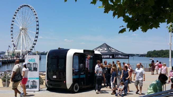
8.3 Local Motors
Website: https://localmotors.com/meet-olli/
Local Motors, an American automobile manufacturing company, developed the world’s first 3D printed transit
vehicle – Olli, a self-driving shuttle. Local Motors design engineers are able to reduce tooling costs by 50% and
reduce overall production time by 90%, all while keeping part production in-house using tools like the MakerBot
Replicator+, a cloud-enabled desktop 3D printer40. Olli made its debut in National Harbor, Maryland (see Figure
25) in June 201641, where it traveled on local public roads within the boundaries of National Harbor in its trial run.
Figure 25. Local Motors’ Olli on demo in National Harbor, Maryland.42
To use Olli, a rider will use the Modally mobile app to book a ride and set your destination, similar to other ride-
sharing programs. Olli is equipped with IBM Watson Internet of Things (IoT) technology, which allows interaction
with the vehicle. This advanced vehicle technology allows passengers to converse with Olli in such a way that
creates more intuitive and interactive experiences due to the nature of its cognitive computing capability.
Together, IBM and Local Motors have produced a vehicle that combines the capabilities of a chauffeur, a tour
guide, and a technology expert to communicate with passengers using spoken conversational language43. In
addition to casual conversation, Olli has the ability to update passengers for the duration of the ride, taking into
account upcoming traffic, weather, or other potential issues that may affect the commute. Table 19 presents the
technical specifications of Local Motors’ Olli.
40
https://www.makerbot.com/local-motors-case-study/
41
https://localmotors.com/meet-olli/
42
https://localmotors.com/2017/06/01/local-motors-celebrates-national-autonomous-vehicle-day/
43
https://www-01.ibm.com/common/ssi/cgi-bin/ssialias?htmlfid=WW112356USEN
33You can also read