Skydiving Technique Analysis from a Control Engineering Perspective: Developing a Tool for Aiding Motor Learning
←
→
Page content transcription
If your browser does not render page correctly, please read the page content below
Springer Nature 2021 LATEX template

                                                 Skydiving Technique Analysis from a Control Engineering
                                                 Perspective: Developing a Tool for Aiding Motor Learning
arXiv:2201.05917v1 [eess.SY] 15 Jan 2022

                                                                           Anna Clarke1* and Per-Olof Gutman2
                                                  1* Technion Autonomous Systems Program (TASP), Technion - Israel Institute of
                                                                           Technology, Haifa, 32000, Israel.
                                                   2 Faculty of Civil and Environmental Engineering, Technion - Israel Institute of

                                                                           Technology, Haifa, 32000, Israel.

                                                            *Corresponding author(s). E-mail(s): anna shmaglit@yahoo.com;
                                                                      Contributing authors: peo@technion.ac.il;

                                                                                               Abstract
                                                This study offers an interdisciplinary approach to movement technique analysis, designed to deal
                                                with intensive interaction between an environment and a trainee. The free-fall stage of skydiving is
                                                investigated, when aerial manoeuvres are performed by changing the body posture and thus deflect-
                                                ing the surrounding airflow. The natural learning process of body flight is hard and protracted
                                                since the required movements are not similar to our daily movement repertoire, and often counter-
                                                intuitive. The proposed method can provide a valuable insight into the subject’s learning process
                                                and may be used by coaches to identify potentially successful technique changes. The main novelty
                                                is that instead of comparing directly the trainee’s movements to a template or a movement pattern,
                                                extracted from a top-rated athlete in the field, we offer an independent way of technique analysis.
                                                We incorporate design tools of automatic control theory to link the trainee’s movement patterns to
                                                specific performance characteristics. This makes it possible to suggest technique modifications that
                                                provide the desired performance improvement, taking into account the individual body parameters
                                                and constraints. Representing the performed manoeuvres in terms of a dynamic response of closed-
                                                loop control system offers an unconventional insight into the motor equivalence problem. The method
                                                is demonstrated on three case studies of aerial rotation of skilled, less-skilled, and elite skydivers.

                                                Keywords: sports technique, feedback control, motor learning, degrees-of-freedom

                                           1 Introduction                                              movements are not similar to our daily move-
                                                                                                       ment repertoire, and are often counter-intuitive.
                                           Skydiving involves skilful body movement to con-            The stressful environment, causing muscle tension
                                           trol free-fall. While skydivers fall near terminal          and blocking kinaesthetic feedback, exterocep-
                                           vertical velocity they alter their body posture,            tive sensory overload, and a very limited prior
                                           thus deflecting the air flow and initiating a great         information on desired body postures constitute
                                           variety of solo and group aerial manoeuvres. Mas-           additional learning challenges. Skydiving body
                                           tering body flight is naturally difficult and pro-
                                           tracted. The reason is that the required body

                                                                     1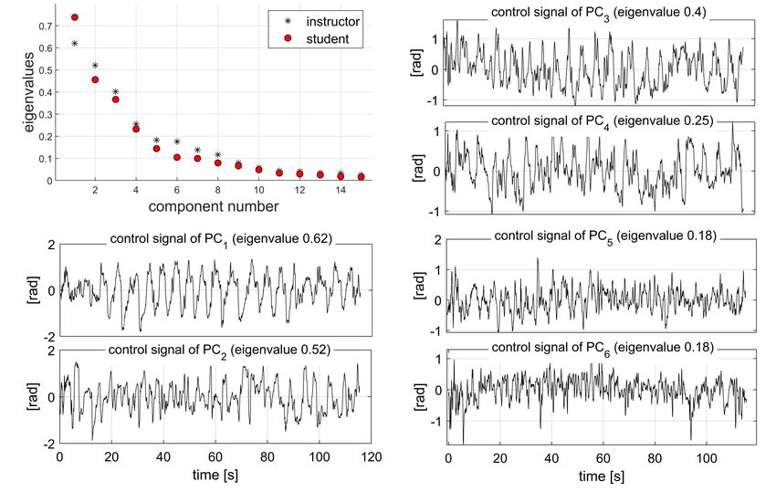
Springer Nature 2021 LATEX template

movements depend highly on individual anthro-          multiple techniques can be adopted to generate
pometric, clothing, and equipment factors. There-      some of the mechanical variables due to human
fore, coaches cannot predict what movements will       motor equivalence.
be required from trainees for performing even the          Other conventional technique analysis meth-
simplest manoeuvres, like falling straight down.       ods, such as variability/ temporal analysis and
Moreover, they cannot describe even their own          phase portraits, suffer from some pitfalls: collec-
joint movements, since their bodies perform them       tion of only partial biomechanical data that are
automatically before being aware that posture          insufficient for analysis of the whole skill, and
adjustments are required. These joint rotations        focusing only on some variables or aspects believed
are usually small, often unnoticeable on a video       to most affect performance or best represent learn-
recording. The coaches give only general rec-          ing progress. See e.g.: Davids et al (2005); Federolf
ommendations regarding relaxation, visualization,      et al (2012); Hamill et al (2000); Lamb and
and focus of attention. For a qualitative descrip-     Stöckl (2014); Müller and Sternad (2004); Mykle-
tion of common skydiving moves, see Newell             bust (2016); Scholz and Schöner (2014); Stergiou
(2020). In Clarke and Gutman (2017) a simulation       (2016); Sternad (2018).
of free-fall dynamics was developed. It predicts the       Most often, the methods analysing sports tech-
skydiver’s motion in the 3D space given a sequence     niques focus on comparing the movement of the
of body postures, and, therefore, can be utilized      trainee to a template/ coach/ top rated athlete
for studying the skydiving technique.                  (e.g. Ghasemzadeh and Jafari (2011); Federolf
    Technique is the way an athlete’s body exe-        et al (2014); Gløersen et al (2018)). Moreover,
cutes a specific sequence of movements Gløersen        required movements are usually well known and
et al (2018); Lees (2002). It can be viewed as an      have large amplitude, as in kicks, swings, poles
athlete’s repertoire of movement patterns: com-        placement. Thus, the analysis focuses mainly on
binations of body Degrees of Freedom (DOFs)            the timing of those movements and their small
that are activated synchronously and proportion-       variations (Holmberg et al (2005)).
ally, as a single unit. From the perspective of            Our method aims to be wider-ranging. It is
dynamical systems theory, motor learning is the        designed to analyse mathematically, without tem-
process during which these movement patterns           plates, the technique of a previously unexplored
emerge Schmidt and Wrisberg (2008). First, the         activity that is highly dependent on individual
patterns are simple (coarse), providing just the       body properties, taking into account that all body
basic functionality. As learning continues, the        parts are involved and slight posture variations
movement patterns become more complex (fine),          might have a large influence. Trainees might have
providing adaptation to perturbations and uncer-       different physical condition, age, and even disabil-
tainties, and improved performance. We offer a         ities. As an illustration, skydiving attracts very
new method to link the acquired behaviours of the      diverse participants. The reason is that free-fall
dynamical system to the specific changes in the        manoeuvres do not require a significant muscle
movement patterns, and predict how the move-           power or physical fitness. All manoeuvres are gen-
ment patterns can be altered to provide desired        erated by aerodynamic forces and moments when
performance. Existing quantitative methods of          a skydiver deflects the air flow around his body by
technique analysis attempt to provide similar          changing the posture. Consequently, our method
insight. For example, deterministic modelling is       is designed to deal with an intensive interaction
widely used for analysing swimming, athletics,         between environment and trainee. The method
and gymnastics Chow and Knudson (2011). It             has one sports-specific part (modelling), and one
determines the relation between the performance        general part in which the predicted dynamic
measure and mechanical variables, e.g. horizon-        responses are used for adjusting the technique
tal velocity at take-off point during a somersault.    to make it more efficient. The model comput-
It thus identifies parameters important for per-       ing these responses is driven by the recorded
formance and their target values. Some of those        biomechanical measurements. Thus, we adopt an
parameters may be related to joints positions and      interdisciplinary approach, integrating dominant
rotation speeds, but the full body motion sequence     motor learning concepts with the analytical tools
is usually not provided. Additionally, sometimes       of automatic control theory. We hypothesise that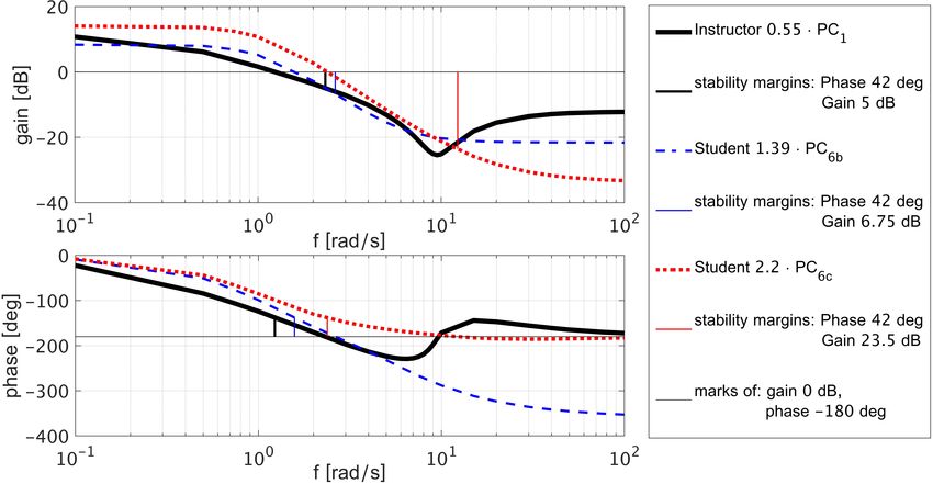
Springer Nature 2021 LATEX template

3

    an individual skydiving technique can be assessed      can be found in our previous work (Clarke and
    if it is interpreted as an actuation strategy of a     Gutman (2017)).
    closed loop feedback control system comprising             The biomechanical model represents the body
    the trainee’s body and the environment.                segments in terms of simple geometrical shapes
                                                           and calculates the local centre of gravity and
    2 Materials and Methods                                principal moments of inertia for each segment. A
                                                           set of rotation quaternions linking each two seg-
    One professional skydiving instructor with over 30     ments enables computation of the overall centre
    years of experience and 15000 jumps, one ama-          of gravity, inertia tensor, and their time deriva-
    teur skydiver with less than 10 years of experience    tives. The model has to be provided with a set
    and 1000 jumps, and one elite skydiver compet-         of parameters, expressing body size, shape, and
    ing in the discipline Relative Work (RW) with          weight of the skydiver under investigation. The
    25 years of experience, 2500 jumps and numer-          dynamic equations of motion, derived following
    ous hours of wind tunnel training participated in      the Newton-Euler method, provide six equations:
    the study. The three participants will be here-        3D forces and moments. The kinematic model
    after referred to as: Instructor, Student, and Elite   computes the body inertial orientation, and angles
    Skydiver, respectively. The Student is still pursu-    of attack, sideslip, and roll of each segment rela-
    ing improvement of his personal technique. Since       tive to the airflow. These angles are used in the
    each jump has about 30 seconds of training time,       aerodynamic model to compute drag forces and
    his total free-fall manoeuvring experience does not    aerodynamic moments acting on each segment.
    exceed 8.5 hours. Therefore, his movement pat-         The total aerodynamic force and moment together
    terns are coarse, and some of the body DOFs            with the gravity forces are substituted into the
    are still locked. The flow of the study included       equations of motion. The aerodynamic model is
    collecting the body movement data from the par-        formulated as a sum of forces and moments act-
    ticipants, processing it by the means of Principal     ing on each individual segment, modelled similar
    Component Analysis (PCA), and analysing the            to aircraft aerodynamics - proportional to veloc-
    results by the means of a Skydiver Simulator           ity squared and to the area exposed to the airflow.
    developed for this purpose.                            The model includes six aerodynamic coefficients
                                                           that were experimentally estimated, and has to be
    2.1 Dynamic simulation of the                          provided with a set of configuration parameters
        human body in free-fall                            specific to the skydiver under investigation (type
                                                           of parachute, helmet, jumpsuit, and weight belt).
    The dynamic simulation of the human body in                The skydiving simulator output was experi-
    free-fall is essential for our technique analysis      mentally verified: Various skydiving manoeuvres
    method. Therefore, a simulation that receives a        in a belly-to-earth pose were performed by differ-
    sequence of body postures and computes position,       ent skydivers in a wind tunnel and in free-fall, and
    orientation, and linear and angular velocities of      the recorded posture sequences were fed into the
    the skydiver model in a 3D world was developed,        simulator. The six tuning parameters related to
    see Clarke and Gutman (2017). The inputted pos-        the aerodynamic model (maximum lift, drag, and
    tures can be recorded, transmitted in real-time, as    moment coefficients; roll, pitch, and yaw damp-
    well as synthetically generated, or even inputted      ing moment coefficients) were selected so that all
    via a keyboard using a graphical user interface,       the manoeuvres were closely reconstructed. The
    specifically designed for this purpose. The sim-       errors RMS in angular and linear (horizontal and
    ulation is implemented in Matlab and it has a          vertical) velocities were 0.15 rad/s, 0.45 m/s (hori-
    continuous graphical output, which shows a figure      zontal), and 1.5 m/s (vertical), while the velocities
    of a skydiver in its current pose moving through       amplitudes were 7 rad/s, 15 m/s, and 65 m/s,
    the sky. The sky has a grid of equally spaced half-    respectively.
    transparent dots, so that the skydiver’s manoeu-
    vres can be easily perceived by the viewer. The
    modules comprising our skydiving simulator are
    briefly described below, while the exact equations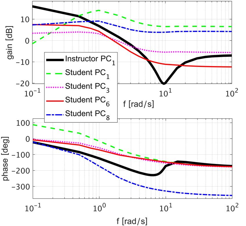
Springer Nature 2021 LATEX template

2.2 Equipment                                          as they could within this session, while prevent-
                                                       ing any horizontal or vertical displacement relative
The X-Sens body movement tracking system
                                                       to the initial body position in the centre of the
Roetenberg et al (2009) was chosen for the purpose
                                                       tunnel. This is an essential skydiving skill.
of getting an accurate measurement of a full body
posture, meaning knowing the relative orientation
(three DOFs) of all relevant body segments. It pro-
                                                       2.4 Data processing
vides a suit with 16 miniature inertial sensors that   2.4.1 Extracting and visualising the
are fixed at strategic locations on the body. Each           movement patterns
unit includes a 3D accelerometer, 3D rate gyro-
scope, 3D magnetometer, and a barometer. The           The movement patterns were extracted from the
X-Sens motion tracking suit can be worn under-         X-Sens data by means of PCA - a method widely
neath conventional skydiving gear. It has a battery    used for analysing human motion in general and
and a small computer located on the back and           sports technique in particular, see Federolf et al
not restricting the skydiving-specific movements.      (2014) for a review. PCA uses Singular Value
The X-Sens output is transmitted or recorded at        Decomposition (SVD) of the recorded motion data
240 Hz. Each measurement set includes the ori-         in order to find movement patterns. In our case,
entation of 23 body segments (pelvis, four spine       X-Sens data consists of inertial orientation of
segments, neck, head, shoulders, upper arms, fore-     23 body segments. For skydiving in a belly-to-
arms, hands, upper legs, lower legs, feet, toes)       earth pose such a detailed posture measurement is
relative to the inertial frame, expressed by quater-   superfluous, hence some segments can be united.
nions. The measurements accuracy is less than          Our skydiver body configuration Clarke and Gut-
5 degrees RMS of the dominant joint angles             man (2017) is defined by 16 rigid segments (pelvis,
Schepers et al (2018).                                 abdomen, thorax, head, upper arms, forearms,
    The experiments took place in a wind tunnel        hands, upper legs, lower legs, and feet), and 15
(diameter 4.3 m, height 14 m), which is a widely       joints (lumbar, thorax, neck, shoulders, elbows,
used skydiving simulator, where the air is blown       wrists, hips, knees, ankles). The relative orienta-
upwards at around 60 m/s - an average terminal         tion of connected segments is defined by three
vertical velocity of skydivers in a belly-to-earth     Euler angles (the sequence of rotation is shown in
pose. The human body floats inside the tunnel          Fig. 1), which are computed from the recorded X-
replicating the physics of body flight. The experi-    Sens quaternions. The data matrix is constructed
ments were videoed for future reference, see Online    from 3·15 rows and 120·240 columns, since there
Resources 1-3.                                         are 15 joints, each with 3 DOFs, the sampling fre-
                                                       quency is 240 Hz, and each tunnel experiment is
                                                       120 s. From each data row we subtract its mean,
2.3 Measurement procedure
                                                       whereas normalization of rows is not required in
The Instructor, Student, and Elite Skydiver were       our case, since all rows have the same units and
in turn equipped with the X-Sens suit and per-         the differences in variability are meaningful. Com-
formed the calibration procedures defined by X-        puting the SVD results in a diagonal matrix S and
Sens that are necessary for the convergence of         unitary matrices U and P C, such that:
the measurement system. The participants’ body
segments and height were measured and inputted                        dataT = U · S · P C T            (1)
into X-Sens software, as well as into the Skydiving
Simulator, described Sect. 2.1, along with weight,     The matrix P C of size 45 by 45 contains the Prin-
helmet size, and jumpsuit type, worn on top of the     cipal Components: eigenvectors that define the
X-Sens suit.                                           components of the skydiver’s turning technique,
    Next, the participants entered the wind tunnel     hereafter referred to as movement components.
and performed 360 degrees turns to the left and        The 45 diagonal elements of S are the eigenval-
to the right in a belly-to-earth pose during two       ues corresponding to each movement component,
minutes – a typical wind tunnel session. The par-      with more dominant components having larger
ticipants were instructed to perform as many turns     eigenvalues. Projecting the original data into the
                                                       principal components provides the time evolution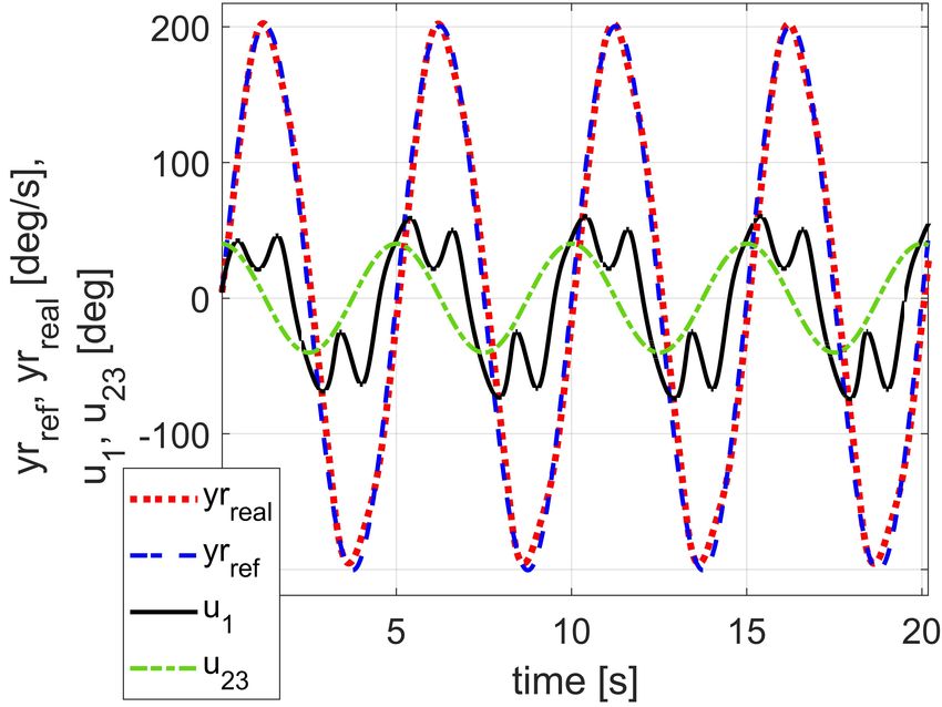
Springer Nature 2021 LATEX template

5

                                                             of the movement component being engaged, and
                                                             will be referred to as the pattern angle, since each
                                                             movement component defines a certain pattern of
                                                             coordination contributing to the total variance of
                                                             the posture.
                                                                 The Skydiving Simulator can be used to ani-
                                                             mate a specific movement component multiplied
                                                             by any synthetically constructed or recorded con-
                                                             trol signal. We often use a sine wave with ampli-
                                                             tude A = 1 rad and frequency f = 1 Hz to animate
                                                             PCA movement components:

                                                                   posei (t) = Npose + A · sin(ω · t) · P Ci
                                                                                                                (4)
                                                                                 ω =2·π·f

                                                             This makes it possible to give an athlete a very
    Fig. 1: Pose defined by all zero Euler angles (top),
                                                             detailed visual feedback of coordinative structures
    and a standard neutral pose (bottom). For each
                                                             comprising his movement repertoire.
    limb the Euler angles ψ, θ, φ are rotations around
                                                                 The Skydiving Simulator fed by the sum of all
    Z, Y , X axis of the coordinate system attached to
                                                             identified PCA movement components, multiplied
    the parent limb
                                                             by the corresponding control signals, will recon-
                                                             struct the performed manoeuvres. However, if we
    coefficients of each of the components, i.e. their       choose to input specific PCA movement compo-
    engagement as a function of time. These coeffi-          nents, multiplied by the recorded or synthetically
    cients have a role of control signals in Automatic       generated control signals, we can obtain answers
    Control Systems, and are the rows of the following       to a great variety of interesting questions related
    matrix:                                                  to the skydiving skill and its acquisition process.
                                                             Below we describe the analysis configurations that
              ControlSignals = P C T · data            (2)   provided the most useful insight.

    The skydiver’s pose at time t is composed as:            2.4.2 Manoeuvre generated by a given
                                                                   PCA movement component
                                 45
                                 X                           Each movement component reconstructed by PCA
            pose(t) = Npose +          αi (t) · P Ci
                                                             has a corresponding normalized eigenvalue in the
                                 i=1
                                                             range [0, 1]. Only a few PCA components are
                αi (t) = ControlSignali (t)
                                                       (3)   expected to have eigenvalues greater than 0.2,
                                 120·240
                           1      X                          hereafter referred to as dominant components. An
           Npose [j] =                   data[j, k]          accepted interpretation of these values is the per-
                       120 · 240
                                   k=1                       centage of total posture variability a movement
                       for j ∈ [1, 45]                       component is responsible for, see Gløersen (2014);
                                                             Hollands et al (2004). We seek a deeper insight:
    where ControlSignali (t) is value from row i of          describing the exact role of a given PCA move-
    matrix ControlSignals corresponding to time t,           ment component in the overall manoeuvre. This
    i.e. from column t · 240; Npose [j] is the entry j       is achieved by feeding the Skydiver Simulator by
    of the column vector Npose containing the mean           each dominant movement component with:
    of the sequence of recorded postures and, thus,
    representing the neutral pose; and P Ci is the           1. a synthetic periodic control signal (Eq. (4))
    eigenvector (with norm 1) defining the movement          2. a step input: posei (t) = Npose + A · P Ci
    component i, i.e. column i of matrix P C. Thus,          Notice, that in the latter case the pose is constant
    the control signal αi (t) is the angle in radians        in time and its difference from the neutral pose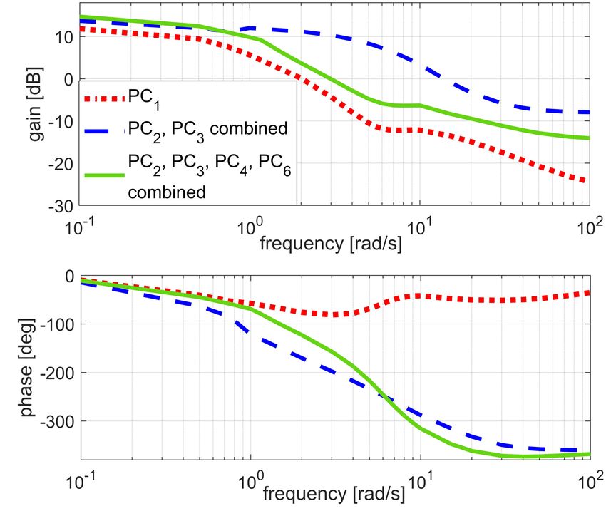
Springer Nature 2021 LATEX template

is A · P Ci . For A = 1 rad this quantity will be            whereas, if only P C1 out of all the 45 PCA move-
referred to as a movement pattern with dimen-                ment components had influence on the yaw rate,
sions, as opposed to a dimensionless eigenvector             Sim1 would be one.
P Ci . The frequency and amplitude of the control
signal in Eq. (4) are chosen to obtain significant           2.4.4 Dominant DOFs in a given PCA
and yet feasible pose changes in time.                             movement component
                                                             Each PCA movement component that generates
2.4.3 PCA movement components
                                                             a meaningful manoeuvre can be further investi-
      required to reconstruct the
                                                             gated. Consider feeding the skydiver simulator by
      original manoeuvre                                     a given PCA movement component, i.e. by a given
The following method provides an insight on how              eigenvector P Ci that has 45 elements, each repre-
many PCA movement components are required                    senting a joint rotation DOF. Instead of engaging
to reconstruct the manoeuvre under investiga-                all DOFs, only an increasing sub-set of these
tion. It suggests feeding the skydiver simulator             DOFs will be engaged in each simulation, starting
by a different amount of dominant PCA move-                  from the elements of P Ci with highest absolute
ment components with the corresponding control               values. This way, each element k, k ∈ [1, 45] of the
signals from the experiment:                                 body pose is computed at every instant of time as:
                                 n
                                                                           (
                                 X                                       Npose [k] + αi (t) · P Ci [k], k ∈ keng
        posen (t) = Npose +            αi (t) · P Ci   (5)   posei [k] =
                                 i=1
                                                                         Npose [k],                     otherwise
                                                                                                               (8)
where n is the number of chosen PCA movement                 where keng is a set of indices of P Ci elements
components. For n = 45 we obtain pose45 (t) - an             being engaged. This will make it possible to deter-
exact pose the skydiver had during the experiment            mine which DOFs within the studied movement
at every instant of time. Since the manoeuvre in             component are most important for performing the
our experiment was turning, its outcome can be               manoeuvre associated with this component.
described by yaw rate. In order to compare the
outcome produced by different pose inputs, we                2.4.5 Synergies of PCA movement
define the total discrepancy between the yaw rate                  components
profiles Ω45 (t) and Ωn (t) resulting from pose45 (t)
and from posen (t), respectively, accumulated dur-           Synergies of PCA movement components can be
ing the time of the experiment T = 120 s, which              determined by activating a combination of two or
included N = 120                  1                          more components with synthetic periodic control
                 δt steps, δt = 240 s:
                                                             signals that are similar to the signals contained in
                  N
                  X                                          the relevant rows of matrix in Eq. (2). PCA con-
         Errn =         |Ω45 (k) − Ωn (k)| · δt        (6)   trol signals can be plotted in the same figure and
                  k=1                                        examined for any apparent correlation between
                                                             them, such as phase shift. If found, such synergies
The similarity of the outcome manoeuvres can be              can be tested in simulation. This allows identi-
defined as:                                                  fying less dominant components that compensate
                                                             for undesirable effects more dominant components
             Simn = 1 − Errn /Err0                           might have on the overall manoeuvre.
                        N
                        X                              (7)
              Err0 =          |Ω45 (k)| · δt                 2.5 Analysis of movement patterns
                        k=1
                                                                 from a control engineering
where Err0 is the error if the skydiver doesn’t                  perspective
manoeuvre at all by keeping the neutral pose at              The key of our method is determining the poten-
all times. Thus, if the component P C1 had no                tial effectiveness of the identified movement com-
influence on the yaw rate, Sim1 would be zero,               ponents: how well they fulfil their roles, reveal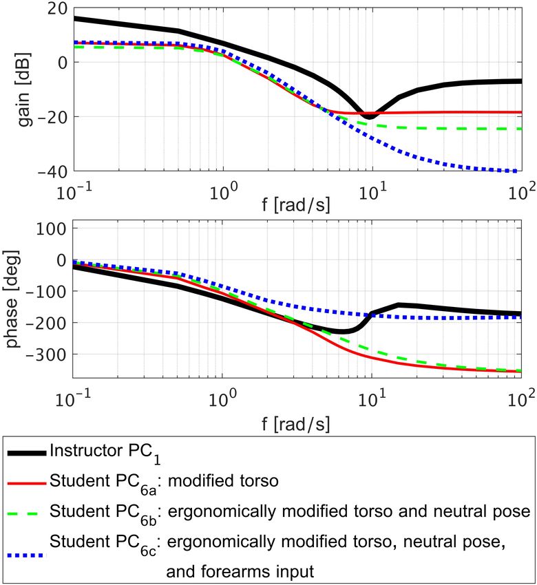
Springer Nature 2021 LATEX template

7

    Fig. 2: Block diagram of a hierarchical closed-loop feedback control system: skydiver performing manoeu-
    vres in free-fall. Body actuation examples show the movement pattern PC1 (the first Principal Pattern
    extracted from the turning experiment with the Instructor) with control signals (dark figures) compared
    with the neutral pose (light figures).

    the pitfalls and possible ways to eliminate them.     of realistic activities. For instance, torques and
    Our method is intended to be a tool for coaches       forces applied by joints and muscles in free-fall are
    that can analyse why certain posture changes          usually very small since all the manoeuvres are
    generate faster manoeuvres, performed with less       executed by the aerodynamic forces and moments,
    effort, or greater precision; and compute indi-       which are generated by only slight changes in the
    vidual modifications for the trainee’s movement       body posture. For these reasons, we offer a new
    patterns, which could be naturally produced by        approach to exploration of the DOFs problem and,
    the CNS in due course. One of the central prob-       thus, technique evaluation.
    lems in the motor learning field is Bernstein’s           Let’s consider a skydiver performing free-fall
    DOFs problem Bernstein (1967): How does the           manoeuvres from a perspective of automatic con-
    CNS choose which DOFs to use for a certain move-      trol theory. Manoeuvre execution can be rep-
    ment? We offer in this section a novel insight into   resented as a hierarchical closed-loop feedback
    this problem applied to manoeuvring in free-fall.     control system, as shown in Fig. 2. The inner con-
    In the literature it is usually assumed that move-    trol loop is closed inside the body actuation block,
    ment patterns are solutions of optimizing some        where the command signal, issued for the specific
    cost function. Suggested costs include mechani-       movement patterns, is compared to the feedback
    cal energy consumption, joints acceleration/jerk,     from body proprioceptors triggering the necessary
    amount of torques/forces applied by joints/mus-       adjustments. The outer control loop has a role
    cles Berret et al (2011). These cost functions        of an automatic pilot in autonomous systems: an
    are tested, for example, on arm reaching move-        automatic controller that interprets the disparity
    ments under some disturbances. However, such an       between the desired and sensed linear and angu-
    approach may not always capture the dynamics          lar velocities in terms of an actuator command.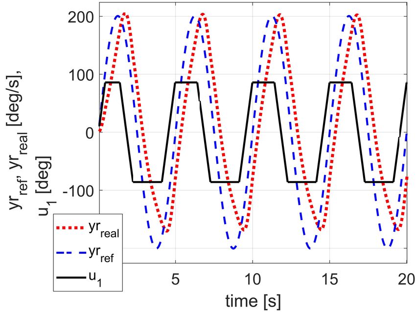
Springer Nature 2021 LATEX template

For example, let’s consider the turning manoeuvre           An example of such analysis is given in Clarke
discussed in our study case. The desired yaw rate       and Gutman (2017), where we compared two
is compared with the actual body yaw rate sensed        movement patterns for turning obtained from
by the eyes and vestibular system, and accord-          observing two types of students: novice and
ing to the disparity the automatic pilot issues         advanced. Both patterns consisted of only four
a command signal for the pattern P C1 . Next,           DOFs (associated with shoulders) but produced
this command is implemented by the body (at a           plants with very different characteristics. The
much higher rate than the outer loop) and the           plant actuated by the ’novice’ pattern had a
resulting joints rotation and posture becomes an        resonance and anti-resonance pair around the fre-
input to the equations of motion, that propagate        quencies of a desired bandwidth. It was impossible
the position, orientation, and motion of the sky-       to design a yaw rate controller for this plant that
diver in a 3D world. In Automatic Control Theory        would satisfy a minimal set of reasonable speci-
a combination of process and actuator is called         fications. This may explain the fact that novice
plant. As shown in Fig. 2, in our skydiver model,       skydivers turn very slowly, whereas initiating a
the plant that the automatic pilot has to control       faster turn causes them to lose stability (e.g. flip to
includes: actuator - body actuation using a spe-        back). However, the resonance and anti-resonance
cific movement pattern; process - skydiver free-fall    pair did not exist in the plant actuated by the
dynamics, and sensing.                                  pattern of the advanced skydiver who was able
     The complexity of an automatic pilot and its       to perform fast and stable turns. Transfer func-
performance (how fast and accurate it tracks the        tions are constructed according to the correlation
desired yaw rate profile) depend on the dynamic         method Ljung (1998), while the Skydiving Sim-
characteristics of the plant. When control engi-        ulator acts as a virtual spectrum analyser. It is
neers design an automatic pilot for autonomous          fed with a sequence of poses constructed from the
platforms they usually have a set of requirements       pattern under investigation (the PCA movement
regarding these characteristics and analytical tools    component P Ci ) inputted in a form of a sine wave
for examining the plant and its properties. We          (Eq. (4)) with different angular frequencies (in our
believe that the same control considerations are        case: 0.01 ≤ ω ≤ 100 rad/s). For each frequency,
important for a natural automatic pilot built into      the gain G(ω) and the phase Φ(ω) of the desired
an athlete’s mind/ body. The body’s natural con-        transfer function are computed as:
troller will achieve a better execution of a desired                             p
manoeuvre if the plant possesses certain (conve-                               2 yc2 + ys2
nient for control) qualities. The plant, in its turn,                   G(ω) =
                                                                                      A
strongly depends on the choice of movement pat-                                          yc
                                                                         Φ(ω) = arctan
terns that are used for body actuation. Thus, we                                         ys
suggest studying the dynamic characteristics of                          Z nT                                 (9)
the plant actuated by a movement pattern under                      yc =      Ω(t) · cos(ω · t)dt
                                                                               0
investigation. One of the basic characteristics is                         Z       nT
the transfer function, which defines the relation                   ys =                Ω(t) · sin(ω · t)dt
between the input and output signal of a system,                            0
mathematically defined using Laplace transform
Åström and Murray (2010). For skydiving, the          where A is the amplitude of the movement pat-
input is a pattern control signal, and the output is    tern angle, T = 2π/ω, n is the number of periods
a state variable (skydiver’s acceleration/ velocity/    taken for analysis. We used n = 10 cycles, start-
position/ orientation) associated with this pat-        ing after the transient, i.e. after the yaw rate had
tern. For the turning manoeuvre it will be the          reached periodic steady state. Ω(t) is the yaw rate
transfer function from the pattern angle to yaw         of the skydiver computed by the simulator, and
rate. In the general case, multiple transfer func-      the integrals are approximated via the trapezoidal
tions may be constructed: from the input signal         method. Next, a Bode plot of the transfer function
of each dominant movement component identified          is created, where the gain in dB is: 20 · log10 G(ω).
by PCA to each significant state variable.              This procedure is repeated for different ampli-
                                                        tudes A of the input signal in order to verify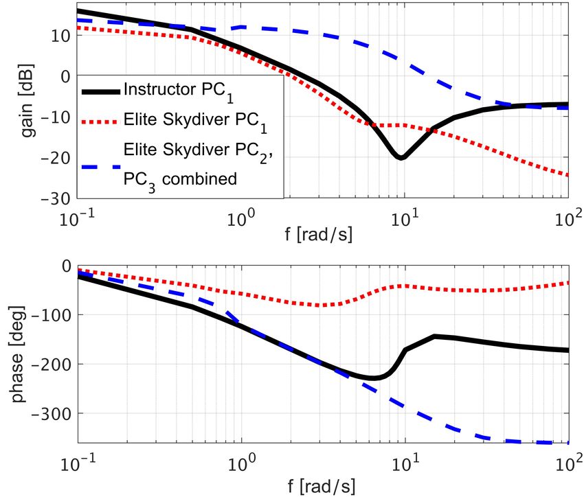
Springer Nature 2021 LATEX template
9
the linear behaviour of the plant in the chosen 4. Investigation of the three next dominant PCA
range of amplitudes. In case of a linear plant all movement components shows that:
the obtained transfer function values for a given • P C2 provides fall rate adjustments by engaging
frequency will be identical.
the arms
• P C3 is responsible for stopping the turns by
3 Results engaging the knees and, to a smaller extent, the
shoulders
3.1 Instructor • P C4 prevents orbiting, meaning a horizontal
The PCA of the recorded body postures of the motion in a large circle, induced by P C1
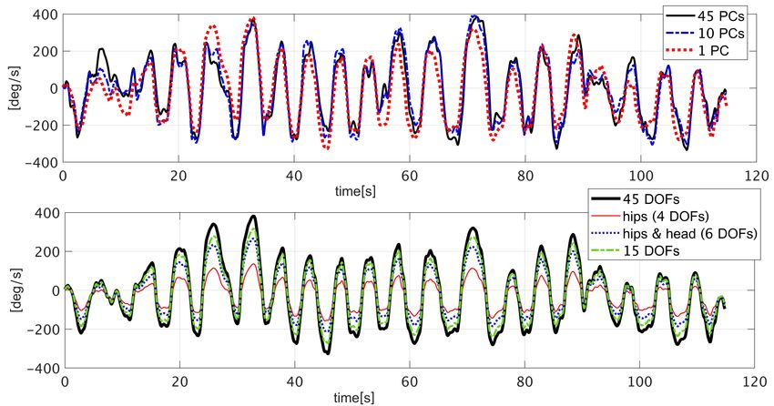
Instructor shows that, similar to other sports (e.g. Engaging P C4 in addition to P C1 in the following
skiing, see Federolf et al (2014)), skydiving also way:
requires from our body to produce about 4-8 sig-
nificant movement components, see Fig. 3. The pose(t) = Npose + P C1 · 1.2 · sin(ω · t)+
PCA control signal of the most dominant move- (10)
P C4 · 0.8 · sin(ω · t + π)
ment component (P C1 ) has the same fundamental
frequency (0.25 Hz) as the recorded yaw rate.
where ω = 2 · π · 0.2 rad/s , compensates for the
This means that the first PCA movement com-
orbiting effect, see Fig. 5.
ponent is responsible for turning, which was the
main objective in this experiment. Other objec-
tives were: keeping distance from all tunnel walls, 3.2 Student
keeping constant altitude relative to the tunnel The Student exhibited many different PCA move-
floor, and transitioning to each turn in the oppo- ment components incorporated for turning (10-15
site direction in minimal time. It seems that 4-5 as opposed to one turning component exploited
PCA movement components are sufficient for per- by the Instructor; the control signals for the six
forming the manoeuvre under investigation, since most dominant components are shown in Online
the control signals of the other PCs resemble noise. Resource 5). Most of these components possess
From Fig. 4 we compute: Sim1 = 0.85, meaning serious pitfalls: are coupled with a horizontal/ver-
that one PCA movement component is sufficient tical motion component, provide a turn only in
to reconstruct 85% of the yaw rate profile. The one direction, and require very large amplitude
highest six values in the eigenvector associated of a control signal. The yaw rate profile of the
with this component are mostly related to the experiment is closely reconstructed by the first
DOFs of head and hips, see Tab. 1 summariz- nine PCA movement components (Sim9 = 0.87,
ing the values of Euler angles representing the see Online Resource 6). Thus, the Student’s move-
movement component and Fig. 1 explaining the ment repertoire includes a greater amount of less
coordinate system. It is known from skydiving efficient coordination patterns. This is verified
experience that hips are very efficient for turn- by the Bode diagram in Fig. 6 comparing the
ing, therefore it is expected that an experienced Instructor’s turning pattern with the student ones,
skydiver engages his hips while turning. The head animated in Online Resources 7-10. The Student’s
movement is also expected: we naturally look in transfer functions from turning patterns to yaw
the direction of motion. An interesting question, rate lack gain at low frequencies (making it hard
however, is whether the head position is impor- to generate a turn and keep high turning rate),
tant for reaching the desired yaw rate. As shown in and lack attenuation at high frequencies (making
Fig. 4, 84% of the yaw rate profile (Sim = 0.84) is it hard to stabilize the closed loop and deal with
reconstructed by engaging only the head and the disturbances and noise). These are the reasons the
hips for P C1 . However, without engaging the head Student reported that he had to constantly fight
only 52% (Sim = 0.52) of the motion is recon- the turbulence of the tunnel airflow and found it
structed. Thus, the head movement combines two hard to generate the movement. The Instructor’s
tasks: looking where the body is going, and act- transfer function has a high gain at low frequen-
ing as a significant aerodynamic control surface. cies providing the efficiency of rotations, and a
Animation of P C1 is shown in Online Resource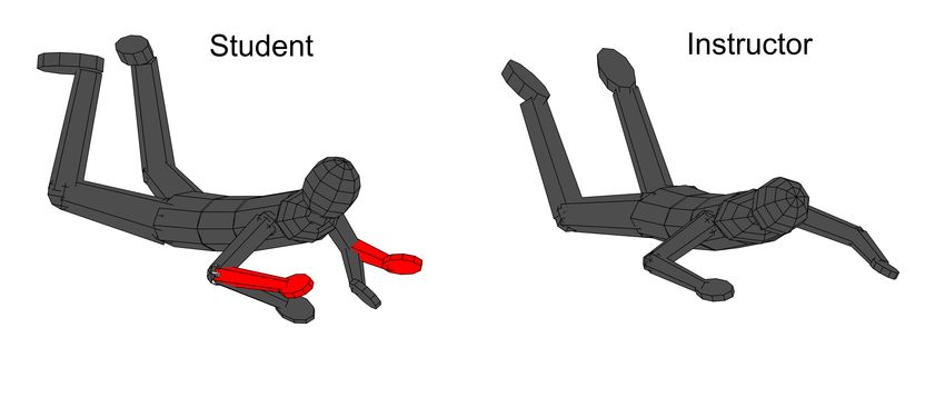
Springer Nature 2021 LATEX template

Fig. 3: Principal Component Analysis of turning: Eigenvalues of the first 15 Principal Components
(PCs), and control signals of the first six PCs extracted from experiment with the Instructor. The pose
is constructed from PCs according to Eq. (3)

gain reduction of about 20 dB per a decade start-           From numerous experiments with various
ing from around 1 rad/s, providing a disturbance        aerial manoeuvres we may hypothesise that
attenuation at high frequencies and replicating         humans can not implement complex dynamic con-
dynamics of an integrator in the innermost (pro-        trollers. Instead, the human body develops such
prioception) loop, recall the control block diagram     movement patterns that produce an ideal plant
in Fig. 2. The higher level loop, which tracks the      for practised manoeuvres, enabling athletes to
yaw rate, includes the dynamics of the closed pro-      operate in a closed loop via a simple control law.
prioception loop: replicating a low pass filter, what
is also seen in the phase plot in Fig. 6.               3.3 Proposing improvement of
    In this way, the transfer function of the plant         Student’s technique with
possesses the desired characteristics of the open
                                                            simulation
yaw rate tracking loop, which can thus consist of
the plant and a proportional controller. In other       The above analysis of the Student’s pattern angles
words, the control signal driving the Instructor’s      to yaw rate transfer functions showed that a signif-
turning pattern can be simply the scaled yaw rate       icant improvement of the student’s technique will
error. In contrast, any of the Student’s plants will    follow from increasing the dynamic stiffness prop-
be either inefficient or unstable under proportional    erty of his plant. Dynamic stiffness, or impedance,
control. It is possible to design a controller with     is the ability of the actuator to resist an external
high order dynamics in order to compensate the          oscillatory load Wang et al (2015); Winters et al
plant pitfalls and achieve a desired closed loop        (1988). Hence, we seek to increase the student’s
behaviour, but it is unlikely that such a controller    ability to reject disturbances at high frequencies,
can be implemented by a human motor system.             such as the turbulence of the wind tunnel air. In
Springer Nature 2021 LATEX template
11
Fig. 4: Comparison of the yaw rate generated by the Skydiving Simulator using: (top) different amounts
of Principal Components (PCs) extracted from experiment with the skydiving instructor; (bottom) P C1
with different amounts of active Degrees-of-Freedom (DOFs), engaged according to Eq. (8)
Fig. 5: Skydiver horizontal position during sim-
ulation of a turning manoeuvre using Principal
Components (PCs) extracted from experiment
with the Instructor
this section we introduce a possible modification Fig. 6: Comparison of the pattern angle to yaw
of one of the student’s turning patterns, so that rate transfer functions of the Instructor and the
this goal is achieved. Student. The movement patterns used for the
The chosen pattern is the PCA movement transfer function generation are the Principal
component P C6 , since its corresponding transfer Components (PCs) extracted from experiments
function has less pitfalls relative to other options.
P C6 is not very dominant (its eigenvalue is 0.11),
which means it was used for only a few of the recently, it still cohabits with other turning pat-
performed turns. The reason, probably, is that terns in the movement repertoire, and is often
this coordination pattern has been formed only overpowered by ’old habits’.
Such a dominant property as dynamic stiffness
is most likely related to the major aerodynamicSpringer Nature 2021 LATEX template
Table 1: Degrees-of-Freedom (DOFs) defining movement patterns that generate rotations of the
Instructor and the Student
Head Right Shoulder Right Elbow Left Shoulder Left Elbow
Pattern θ ψ φ θ ψ φ ψ φ θ ψ φ ψ
I-P C1 15 19 9 -3 -6 -25 12 -13 1 -4
S-P C1 -21 -24 -5 7 -11 -5 12 7 7 -13 6 14
S-P C6 -1 -7 9 -6 -11 -14 5 10 3 20 1
Right Hip Right Knee Left Hip Left Knee Abdomen Thorax
Pattern φ ψ φ ψ φ ψ φ ψ θ ψ θ ψ
I-P C1 -25 -14 7 -5 20 -10 -7 2.5 3
S-P C1 -4 6 5 3 4 6 4 -1 6 -2 7.5
S-P C6 -7 -5 -7 17 -6 -20 1 1 1 1
Note: The symbols φ, θ, ψ in the table head represent Euler angles stated in degrees in order to facilitate their intuitive interpre-
tation. The values represent the quantity 1 [rad] · P C, where P C is the dimensionless movement pattern eigenvector. I-P C1 is the
first principal component extracted from the turning experiment with the Instructor. S-P C1 and S-P C6 are the first and the sixth
principal components extracted from the turning experiment with the Student. The DOFs with absolute values less than 0.5 [deg]
are not shown (angles of wrists and ankles, φ of thorax abdomen and head, and θ of elbows, knees and hips).
surface of the body – the torso. From Tab. 1 it However, in the introduced modification the
can be seen that the torso is activated differently thorax joint tilt is smaller than the abdomen
by the Instructor and the Student during turning. joint tilt, what is opposed to the torso actua-
The Instructor exhibits lateral tilt, whereas the tion observed in the instructor. This difference
Student exhibits axial rotation, especially this is might be caused by differences in body param-
pronounced in his most dominant PCA movement eters, however, prior to experimental verifica-
component P C1 . Notice (from Tab. 1) that axial tion the reason remains uncertain and might be
rotation in P C6 becomes much smaller, and even ergonomic. Therefore, in case a more comfort-
some tilt appears. Modifying P C6 so that the torso able torso movement implies tilting thorax more
tilts instead of rotating (abdomen θ = 2.5 degrees, than the abdomen, the Student is offered a sec-
ψ = 0; thorax θ = 0.5 degrees, ψ = 0) significantly ond option. One change in the Student’s neutral
changes the pattern angle to yaw rate transfer pose provides an option to actuate his torso sim-
function, bringing it very close to the Instructor’s ilar to the Instructor (abdomen θ = 1.5 degrees,
one, see the Bode plot in Fig. 7 labelled ’P C6a thorax θ = 2 degrees), while the transfer func-
modified torso’. Just a couple of degrees of torso tion under investigation remains close to the one
tilt make a great difference. We called this effect of the Instructor (see Fig. 7, Bode plot labelled
the key DOF - DOF that has the most impact on ’P C6b ergonomically modified torso and neutral
shaping the dynamic response. pose’). This change is associated with the positionSpringer Nature 2021 LATEX template
13
It is possible to further improve the trans-
fer function under investigation by increasing the
phase around the current bandwidth frequency.
This will allow using a proportional controller
with a larger gain and extending the bandwidth,
thus performing faster turns with faster transi-
tions between different turning directions. Such
an improvement can be achieved by modifying, in
addition to the DOFs mentioned above, the flex-
ion of the elbows: both elbows flexion values φ
are multiplied by 1.7. The resulting transfer func-
tion is labelled in Fig. 7 as ’P C6c , ergonomically
modified torso, neutral pose, and forearms input’.
The Student’s plant modified as proposed
above can be easily controlled using a proportional
controller, as shown in Fig. 9. Moreover, the latter
modification allows achieving a better gain mar-
gin (23.5 dB) than that of the Instructor’s open
control loop (5 dB).
In this way, rather than mimicking the Instruc-
Fig. 7: Comparison of the pattern angle to yaw tor’s movement pattern our technique improve-
rate transfer functions of the Instructor and the ment method is aimed at shaping the Stu-
Student. The movement patterns used for the dent’s plant. This process, however, requires to
transfer function generation are the first Principal decide, first of all, on design specifications: desired
Components (PC) of the Instructor and the sixth dynamic properties of the plant under investiga-
PC of the Student, modified in various ways tion. In the next sub-section we address manoeu-
vres that involve contradicting dynamic character-
istics. The rotations performed at a competitive
level require to shift the stability-agility trade-
off towards the latter, in order to produce the
fastest and most accurate rotations a human body
is capable of.
3.4 Elite Skydiver
By the means of PCA three movement compo-
Fig. 8: Comparison of the neutral pose of the nents producing turning were extracted from the
Instructor and the Student. Modification of the experiment with the Elite Skydiver. See Online
Student’s forearms position (red) Resource 11- 13 for the animation of these pat-
terns, and Online Resource 14 for the PCA details
and reconstruction of the measured yaw rate pro-
of the forearms: in the Student’s recorded neu- file in simulation. The first Principle Component
tral pose the forearms are too far down (relative produces a plant that can be stabilized with
to the Instructor’s neutral pose and also to the a proportional controller, as in the case of the
standardly accepted neutral pose). This is fixed Instructor rotations. Moreover, it has better phase
by decreasing the shoulder’s internal rotation (by characteristics, allowing for very large phase and
35 degrees), as shown in Fig. 8. Notice that P C6 gain margins, since this system is Minimum Phase,
must be normalized after modification for compu- see Fig. 10. It is hence possible to control this
tation of the transfer function according to Eqs. 4 plant with a high gain proportional controller.
and 9. However, we must bear in mind that all human
joints have limitations, therefore, high gain willSpringer Nature 2021 LATEX template
Fig. 9: Comparison of the open yaw rate loop transfer functions of the Instructor and the Student. The
movement patterns used for the transfer function generation are the first Principal Components (PC)
of the Instructor and the sixth PC of the Student, modified in torso (P C6b ), and modified in torso and
elbow joint (P C6c ). Both Student plants include a neutral pose modification
improve performance only until the actuation lim- (see Online Resource 15 for simulation recording),
its are reached. Nevertheless, it is advantageous the aerodynamic forces acting on arms and legs
to be able to utilize the whole range of movement acquire components that generate a yaw moment
granted by the body flexibility. depending on lever arms: distances of those limbs
The second and third Principal Components from the centre of gravity.
produce turns only in one direction: right and left, (
respectively. This is due to body engineering: these |α(t)| · P C2 , if α(t) < 0
patterns, as opposed to P C1 , involve an asymmet- pose(t) = Npose +
α(t) · P C3 , otherwise
rical engagement of the hips DOFs, see Tab. 2. In
(11)
P C1 these DOFs are used symmetrically with a
In contrast (see Online Resource 16), applica-
small range of motion: the right hip’s flexion and
tion of P C2 , P C3 causes the roll movement of the
abduction is used along with the same magnitude
upper body, thus creating an angle between the
of left hip’s extension and adduction in order to
torso and the airflow. This generates a large aero-
turn left, and vice-a-versa. In P C2 and P C3 only
dynamic force responsible for the yaw moment,
one hip is used for turning in each direction: P C2
since torso has the largest surface area of all body
generates a right turn using right hip extension
segments. During the initial roll motion the body
and abduction, while P C3 generates a left turn
slightly rotates in the opposite direction, which
using left hip extension and abduction. Thus, for
indicates that this plant is Non Minimum Phase
control purposes these two movement components
(NMP), see Fig. 11. Notice from the phase dia-
can be combined, such that either P C2 or P C3
gram on Fig. 10 that the Instructor’s plant is also
is activated depending on the sign of the control
NMP, however this behaviour is less pronounced,
signal α(t), as shown in Eq. (11).
as also seen from the step response on Fig. 12.
By simulating the skydiver motion caused by
Additionally, the transfer function, associated
a sine input driving Eq. (11) we can see that
with this plant, has high gains for frequencies up
movement components P C2 , P C3 invoke a dif-
to 10 rad/s, whereas the phase at low frequencies
ferent mechanism of turning than that initiated
is similar to that of the plant of the Instructor (see
by P C1 of both skydivers. When P C1 is appliedSpringer Nature 2021 LATEX template
15
Right Shoulder Right Elbow Left Shoulder Left Elbow
Pattern φ θ ψ φ θ ψ φ θ ψ φ θ ψ
P C1 4 -10 -9 -10 10 4 -7 -7 -8 20 11 11
P C2 -6 -2 4 13 -9 2 20 18
P C3 -2 20 -18 -6 2 -4 13 9
Right Hip Right Knee Left Hip Left Knee
Pattern φ θ ψ φ θ ψ φ θ ψ φ θ ψ
P C1 -6 -3 -2 7 -6 -2 -7 -2
P C2 12 17 -18 4 -5 3 2 2 7
P C3 -5 -3 2 -2 -7 12 -17 -18 -4
Head Abdomen Thorax Right Ankle Left Ankle
Pattern θ ψ θ ψ θ ψ θ ψ θ ψ
P C1 -17 -13 -0.5 -0.5 -7 11 -8 9
P C2 -10 -7 -1.4 -0.6 -2 -0.5 5 -19 18 -11
P C3 10 7 1.4 0.6 2 0.5 -18 11 -5 19
Table 2: Degrees-of-Freedom (DOFs) defining movement patterns that generate rotations of the Elite
Skydiver.
Note: The symbols φ, θ, ψ in the table head represent Euler angles stated in degrees in order to facilitate their intuitive interpre-
tation. The values represent the quantity 1[rad] · P C, where P C is the dimensionless movement pattern eigenvector. P C1 , P C2 ,
P C3 are the first three Principal Components extracted from the turning experiment with the Elite Skydiver. The DOFs with
absolute values less than 0.5 [deg] are not shown.
Fig. 10). This means that if the movement com- where t is the simulation time. The controller uti-
ponents P C2 , P C3 are engaged with large control lizing P C1 for body actuation had proportional
inputs, assuming a proportional controller whose and feedforward parts:
gain is larger than about 0.3, the closed loop will
be unstable. As it was mentioned in Sect. 3.2, α1 (t) = 2.5 · (Ωref (t) − Ω(t)) + 0.15 · Ωref (t) (13)
humans are unlikely to be able to implement a
dynamic controller. In the experiment, however, where Ω(t) [rad/sec] is the yaw rate of a vir-
amplitudes reaching 1 rad were observed. tual skydiver in simulation, and α1 (t) [rad] is the
It seems, therefore, that the Elite Skydiver control signal, i.e. the angle of the movement com-
engages the movement components P C2 , P C3 in ponent P C1 , such that the skydiver’s pose at each
open loop: when the right turn is desired P C2 is instant of time is defined as:
engaged proportional to the desired angular accel-
eration, in order to ’throw’ the body into a turn, pose(t) = Npose + α1 (t) · P C1 (14)
and as it turns, P C1 is used in a closed loop to
adjust the turning rate to a desired profile. In It can be seen from Fig. 13a that the desired yaw
order to examine this observation, such a con- rate profile can not be tracked accurately due to
trol strategy was implemented in simulation. A actuation limitations:
sine yaw rate profile was tracked, and the track-
ing performance achieved by a controller based max(|α1 (t)|) = 1.5 [rad]
(15)
only on P C1 was compared to the results obtained dα1 (t)
max = 3.5 [rad/s]
utilizing a combination of the three movement dt
components.
The yaw rate reference signal was: In other words, the movement component P C1
does not allow to change the turning rate so fast.
Ωref (t) = 3.5 · sin(2 · π · 0.2 · t) (12) The delay in tracking the desired yaw rate profile
is 0.5 s. Utilizing the movement components P C2Springer Nature 2021 LATEX template
Fig. 12: Open loop response to the step input
signal driving the movement component P C1
extracted from the rotations experiment with the
Instructor
Fig. 10: Comparison of the pattern angle to yaw The pose at each instant of time is defined as:
rate transfer functions of the Instructor and the
Elite Skydiver. The movement patterns used for pose(t) = Npose +
the transfer function generation are the Principal (
α1 (t) · P C1 + |α23 (t)| · P C2 , if α23 (t) < 0
Components (PCs) extracted from experiments.
A combination of P C2 and P C3 is defined in Eq. α1 (t) · P C1 + α23 (t) · P C3 , otherwise
(11). (17)
where α1 (t) is according to Eq. (13). This con-
trol strategy, which we termed the Superposition,
allows to reduce the tracking delay to 0.05 s and
reconstruct in simulation the fast turns observed
in the experiment, see Fig. 13b.
We thus hypothesize that for each specific
manoeuvre performed at a competition level ath-
letes develop a ’high performance’ pattern (such as
P C2 , P C3 ), what may be analogous to the flight
dynamics of high performance aircraft. Athletes
have to learn from practice how to engage this pat-
tern during the manoeuvre execution, along with
the closed loop control of the manoeuvre.
Fig. 11: Open loop response to the step input sig- Notice that the derivative of the reference sig-
nal driving the movement components P C1 , P C2 , nal in Eq. (16) is known a-priori, as it is related
and P C3 extracted from the rotations experiment to the intended manoeuvre. The closed loop on
with the Elite Skydiver. The pose in the case of the derivative of the yaw rate error, however,
P C2 , P C3 combination is defined according to Eq. may not be possible for human implementation.
(11) It requires to sense/ compute the derivative of
the actual yaw rate and filter out the noise in
real time, what is most likely beyond human abil-
and P C3 significantly improves the performance,
ities. For this reason, we used a feed-forward of
as shown in Fig. 13b. The feedforward control
the reference signal derivative combined with a
signal driving the combination of P C2 , P C3 is
proportional controller, instead of a conventional
(Proportional-Derivative) PD control.
d(Ωref (t))
α23 (t) = 0.16 · (16) Interestingly, there is another way to combine
dt
different movement components. After exploring
other Principal Components, we noticed that P C2Springer Nature 2021 LATEX template
17
(a) pose given in Eq. (14)
Fig. 14: Comparison of the pattern angle to
yaw rate transfer functions, generated by different
combinations of Principal Components extracted
from the rotations experiment with the Elite Sky-
diver. A combination of P C2 and P C3 is defined
in Eq. (11). A combination of P C2 , P C3 , P C4 ,
P C6 is defined according to Eq. (18)
(b) pose given in Eq. (17) 14 is for the value of k = 0.8, whereas it is pos-
sible to obtain any response in between the most
Fig. 13: Simulation of tracking a sine yaw rate agile and the most stable behaviour, thus tuning
profile in a closed loop. The movement compo- the agility-stability trade-off in a continuous way!
nents P C1 , P C2 , P C3 , extracted from the rota- This strategy to combine movement components
tions experiment with the Elite Skydiver, are used we termed the Synergy.
for body actuation Recall the synergy of the Instructor’s Principal
Components P C1 , P C4 given in Eq. (10) for pre-
vention of orbiting (see Fig. 5): A similar synergy
in combination with P C4 for right turns and P C3
can be observed between the movement compo-
in combination with P C6 for left turns allows to
nents of the Elite Skydiver, see Online Resource
construct a set of movement patterns, defined by
14. Moreover, synergies of movement components
the parameter k:
were identified from analysis of other manoeuvres,
pose(t) = Npose + for example, the side slides performed by the Elite
( Skydiver. The details are given in Online Resource
|α(t)| · (P C2 − k · P C4 ), if α(t) < 0 (18) 17, along with the PCA of additional manoeuvres
α(t) · (P C3 − k · P C6 ), otherwise performed by the Instructor, Student, and Elite
Skydiver.
where α(t) is the input signal and k is the factor
reflecting to what extent the additional patterns 4 Discussion
P C4 and P C6 are involved.
Movement patterns in this set produce plants 4.1 Practical perspective
that can acquire any behaviour in between the two
The key idea of our technique analysis method is
extremes: the agility of P C2 , P C3 , and the stabil-
testing the extracted PCA movement components
ity of P C1 . The frequency response shown in Fig.Springer Nature 2021 LATEX template
of the trainees in a Skydiving Simulator and gener- dynamic properties of the body in free-fall actu-
ating transfer functions from a pattern angle to a ated by a PCA movement component under inves-
physical variable associated with a given pattern. tigation. As we have seen in the above analysis the
Simulation tests show what manoeuvre is gen- Bode plot of such a transfer function shows what
erated by each PCA movement component, which dynamic properties need improvement in order to
joint rotation DOFs have a dominant influence, facilitate for the trainee the implementation of
and how many PCA movement components were a given manoeuvre. Moreover, it is possible to
required to perform the given task or exercise. compare the instructor’s and the student’s trans-
This information reflects the skill level of the fer functions, and to check what modifications
trainee and the major pitfalls in his technique, as of the student’s movement pattern can reduce
was demonstrated in our study case. We suggest to the gap between them. Notice, that in skydiv-
interpret the analysis of the Student’s turning pat- ing, comparing the movement patterns directly
terns as the evolution of his movement repertoire: may be less useful, as well as mimicking the
the old habits (P C1 , P C3 ), exploration (P C8 ), movement patterns of a skilled model like the
and on-going progress (P C6 ). Movement compo- instructor. The reason is that the aerodynamic
nents that represent exploration by the trainee of forces and moments generated by moving a cer-
the interaction between his body and the airflow tain limb greatly depend on the individual body
usually include a particularly strong movement shape, height, weight, the type of jumpsuit, and
(a large value in vector P Ci relative to others) the neutral pose, which in its turn depends on
of a certain limb, and in the simulation usu- the body flexibility and centre-of-gravity location.
ally produce a turn in only one direction. The Thus, the same movement of a certain student’s
progress is represented by movement components and instructor’s limb can cause a different type of
that include more unlocked DOFs relative to the motion in a 3D space, or the same type of motion
most dominant PCA movement component, and but in the opposite direction. In this way, from
in the simulation produce faster turns with less the student’s PCA alone the coach cannot know
undesirable horizontal motion. We believe that what tips to give him, as there is no ’template’
one of the most important tasks of a skydiving or a ’correct way’ to perform a move. Whereas,
coach would be identifying an emergence of such the tool proposed above allows the coach to know
components and triggering the student’s body to what performance change will likely be caused
utilize them more during next training sessions. by a change in movement pattern. In our study
The trigger can be found by analysing the PCA case, the coach can recommend the Student to pay
control signals of other movement components and attention that his torso tilts rather than rotates,
the focus of attention at the moment when this to allow a larger range of movement in the elbow
component was first activated. For example, in our joint, and, finally, to pay attention that in the neu-
case, P C6 was triggered when prior to starting the tral pose the forearms are in the same plane as the
turn the skydiver came to a full stop, increased torso. These changes will enable the Student to
fall-rate, and kept a visual reference to an object be less sensitive to the turbulence of the airflow,
outside of the tunnel at his initial heading. Thus, and generate faster turns while not losing stability.
in order to potentially accelerate learning aerial The simulated improvements need to be experi-
rotation, the coach could give this student cues to mentally verified and compared to other practice
stabilize his initial heading in front of the coach, and instruction conditions.
arch his back, and keep eye contact with the coach. Introducing the desired changes into practice
The coach can give a sign to start turning once should be gradual (one change at a time), and,
these conditions are fulfilled. Next, the coach can while performing the manoeuvre, the focus of
expect that the analysis of the following training attention should still be external, e.g. looking at
sessions will show that the preferable movement the instructor as mentioned above. When initiat-
component is more dominant. ing a movement (e.g. a rotation) the trainee should
The second potentially useful tool for coaches consciously apply the desired change (e.g. torso
is constructing transfer functions reflecting the tilt) and pay attention to how it feels and how the
airflow around the body is redistributed. This new
initial response, according to fundamental somaticYou can also read