RS series Mobile equipment fleet safety stop and commands
←
→
Page content transcription
If your browser does not render page correctly, please read the page content below
RS series

                          Mobile equipment fleet safety stop
                                            and commands

      RSEF transmitter / RSRDevice receiver
              (version with electronic housing)

                                  RF switch

   RSEF
transmitter

                                                       RSRDevice
                                                        receiver

              Installation and user manual

                                                             Original version

                                              Doc. ref : 333130B_A006-EN
                                                                   2021/06/11

                                                               Page 1 / 53
Doc. ref : 333130B_A006-EN
                    2021/06/11

                 Page 2 / 53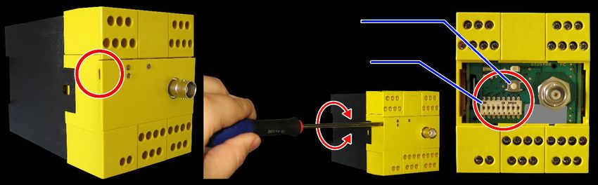
TABLE OF CONTENTS
1    Introduction .............................................................................................. 5
              Safety rules and general precautions ..................................................................................... 5
              Components identification ...................................................................................................... 6
              Products operating principle ................................................................................................... 7
2    Preliminary steps before installation ...................................................... 8
              Factory default settings .......................................................................................................... 8
              RSEF safety transmitter: terminal blocks................................................................................ 9
              Transmitter test wiring (independent from any application) .................................................. 10
              RSRDevice safety receiver: terminal blocks ......................................................................... 11
              Receiver test wiring (independent from any application) ...................................................... 12
              Global system test before installation ................................................................................... 13
3    Modifying the product configuration .................................................... 14
              RSEF transmitter configuration ............................................................................................ 14
              RSRDevice receiver configuration ....................................................................................... 20
4    Wiring the components ......................................................................... 21
              Wiring the RSEF transmitter................................................................................................. 21
              Wiring the RSRDevice receiver ............................................................................................ 22
5    Instructions for safe installation and commissioning ......................... 26
              General information ............................................................................................................. 26
              RSEF transmitter ................................................................................................................. 26
              RSRDevice receiver ............................................................................................................. 26
              Positioning the components and antennas ........................................................................... 27
6    Optional radio components ................................................................... 28
              Radio Frequency switch (ref. VUB090) ................................................................................ 28
              JUMP repeater and RF switch (ref. VUB095) ....................................................................... 28
              Antennas for 433-434 MHz band ......................................................................................... 29
              Antennas for 869, 911-918 MHz band.................................................................................. 29
              Antennas for 920 MHz band ................................................................................................ 30
7    Troubleshooting, Maintenance, Warranty ............................................ 31
              Diagnosis - RSEF transmitter ............................................................................................... 31
              Diagnosis - RSRDevice receiver .......................................................................................... 32
              Connect the RSRDevice to a PC ......................................................................................... 32
              Servicing .............................................................................................................................. 33
              Replacement of RSEF transmitter ........................................................................................ 33
              Inspection and servicing of RSRDevice receiver .................................................................. 34
              Warranty .............................................................................................................................. 34
8    Applicable standards and regulations .................................................. 35
              FCC Rules & Regulations (Federal Communications Commission) ..................................... 35
              IC Regulations (Industry Canada) ........................................................................................ 35
              European guidelines and national laws and regulations ................ Erreur ! Signet non défini.
9    Appendices ............................................................................................. 36
              Component dimensions (mm) .............................................................................................. 36
              Technical characteristics ...................................................................................................... 37
              Environmental data .............................................................................................................. 40
              Safety related parameters .................................................................................................... 40
              RSEF Transmitter case thermal capability ........................................................................... 42
              Miscellaneous ...................................................................................................................... 42
10 Declaration of conformity ...................................................................... 43

                                                                                                           Doc. ref : 333130B_A006-EN
                                                                                                                                              2021/06/11

                                                                                                                                         Page 3 / 53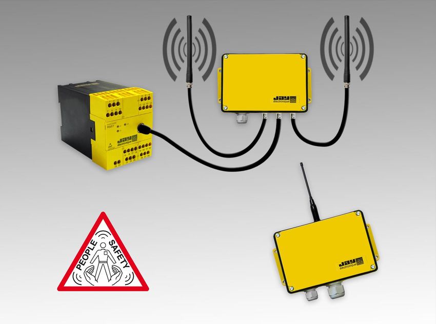
Doc. ref : 333130B_A006-EN
                    2021/06/11

                 Page 4 / 53
1       Introduction

             Safety rules and general precautions

    The RS system is considered as a control and a safety component ensuring an emergency stopping function under the terms
         of the European Machinery Directive. The following safety rules apply to installation and use of the RS system.

    •    For maximum safety when using the system, the instructions given in this manual must be strictly observed.

    •    RS system operators must be appropriately trained and authorised to use the product.

    •    RS system operators must have uninterrupted visibility at all times when performing manoeuvres.

    •    Where several systems are implemented on a single site, different radio frequencies must be used. These should be
         spaced by at least 2 channels (for example, channels 5, 7, 9, …) or by 5 channels when several systems are operating
         within a radius of 10 meters.
         Please contact us for the case of dense installations.

    •    It is not advisable to install the safety transmitter RSEF and safety receiver RSRDevice in the same cabinet to prevent
         disruption of the receiver. If you need to install these two elements in the vicinity, please contact us.

    •    In the event of a malfunction, the installation should be immediately shut down by pressing any emergency stop pushbutton
         and particulary that connected to the safety transmitter RSEF.

    •    If an enabling handle is used for the application, this device must comply with the requirements of
         EN 60947-5-5:2016, EN ISO12100 and EN 60204-1:2016 standards.

    •    All emergency stop pushbuttons used for the                  application,   must   comply   with   the   requirements          of
         EN 60947-5-5:2016 and EN 60204-1:2016 standards

    The product described in this manual is designed to satisfy the requirements of Machinery Directive 2006/42/EC based on
         application of the following standards :

    •    EN ISO 13849-1:2015 for performance level PLe (Category 4)

    •    IEC 62061:2005+AC:2010 + A1:2013+A2:2015 for SIL 3

                                                                                            Doc. ref : 333130B_A006-EN
                                                                                                                           2021/06/11

                                                                                                                    Page 5 / 53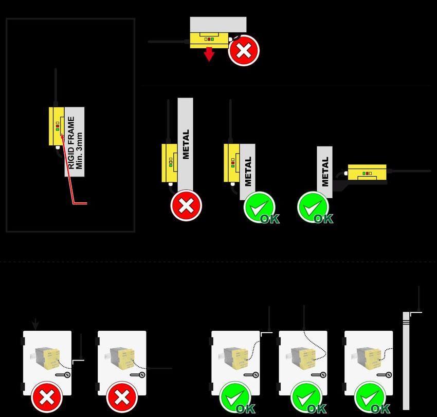
Components identification
The RS “mobile equipment fleet safety stop” solution can be ordered in separate components:

             References                                Elements               Visuals                            Notes

    RSEF41-1 (434 MHz)
                                                                                                   Supplied with:
                                                                                                   - 1x SIM card (inserted inside)
    RSEF91-1 (915    MHz)1
                                                                                                   - 1x VUB060 (BNC elbow)
                                                   RSEF transmitter
                                                                                                   - 1x VUA103AM antenna 3
    RSEF80-1 (869 MHz)
                                                                                                   - 1x USB keycard
    RSEFJ0-1 (920 MHz)2

    RSRD4000-2 (434 MHz)                                                                           Supplied with:
                                                                                                   - 1x VUA001A antenna4
    RSRD9000-2 (915 MHz)
                                                  RSRDevice receiver
                                                                                                    By default, 2 cables glands are
    RSRD8000-2 (869 MHz)
                                                                                                      mounted (M16 and M25)
    RSRDJ000-2 (920 MHz)

                                                                                                    One piece can be sufficient for
    RSW39                                    Serial 232 to USB cable                                  all RSRDevice manual
                                                                                                      maintenance operations

                                                                                                   Supplied with:
    VUB090 (for RSEF)                                                                              - 1x 2-m synchro 3-wire cable
                                                       RF switch                                   welded internally
    VUB095 (for Jump)

                                                                                                    Typically used for:
    VUB202                                        2-meter coaxial cable                             -   RSEF/RFswitch connection
                                                                                                    -   Jump/RFswitch connection

                                                                                                   Supplied with:
    JUT0A110 (433 MHz)                                                                                                         4
                                                                                                   - 1x VUA001A antenna
    JUT9A110 (915 MHz)                              Jump repeater                                   Also available with an internal
                                                                                                      battery instead of a 9-28VDC
    JUTJA110 (920 MHz)                                                                                supply (replace letter A by B)

Any RS “mobile equipment fleet safety stop” solution can be ordered with grouped references specific to any application so as to
simplify orders and to reduce the number of references to be ordered. Please refer to section 6 for specific antenna choices.

1
  Certified according to the FCC IC standard
2
  Certified according to ARIB STD-T108 standard
3
  VUA103BM in 869, 915 MHz and 920 MHz
4
  VUA001B in 869, 915 MHz and 920 MHz

                                                                                            Doc. ref : 333130B_A006-EN
                                                                                                                           2021/06/11

                                                                                                                      Page 6 / 53
Products operating principle
The RS system is used to transmit a safety signal and logic signals from one point of an installation to another.

The RSEF transmitter is designed to trigger the following events onto an unlimited number of RSRDevice receivers:
     - An emergency stop in the event of a problem occurring in the installation
     - Up to 10 commands (which can be combined)

The RSRDevice receiver is integrated in the control component of a machine. It enables (or forbids) operation of the machine and
transmits the possible commands assigned to the buttons connected to the RSEF transmitter.

The RSRDevice receiver stops operation of the machine when any of the following conditions are present :

       Case 1 : Deactivation of a safety input (for example : contact on a gate or an emergency stop) connected to the
                RSEF transmitter
                → Safety interlock subsequent to stop request.

       Case 2 : Action on emergency stop device wired to the RSRDevice receiver.
                → Safety interlock subsequent to stop request.

       Case 3 : Interruption of radio link during use
                When the system is in use, the RSEF transmitter has a continuous radio link with the RSRDevice receiver.
                Should this link be interrupted for more than the passive stop time, the receiver automatically triggers stopping of
                the installation.
                → Safety interlock prior to loss of control of stopping function.

       Case 4 : Detection of a malfunction (see section 7 for troubleshooting)

           Block diagram showing a fixed control panel equipped with RSEF and a Radio Frequency Switch
                           and several mobile machines each equipped with RSRDevice

         Antennas for RSRDevices are to be chosen in accordance with the mechanical design of each piece of equipment
          Emergency stop pushbuttons must comply with the requirements of EN 60947-5-5:2016 and EN 60204-1:2016

                                                                                              Doc. ref : 333130B_A006-EN
                                                                                                                          2021/06/11

                                                                                                                      Page 7 / 53
2 Preliminary steps before installation
This section details the first steps to take so as to become accustomed to the equipment
First, acknowledge the factory settings
Then proceed to the identification of components terminals
Eventually, perform the proposed test wiring and proceed to the standard testing procedure
Factory default settings
Transmitter RSEF
Radio power level ................................................................................. : Fixed, according to RSEF model number
Radio channel number ......................................................................... : 64 (DIP switches 1 to 6: up)
Self check of inputs upon auxiliary supply activation....................... : NO (DIP switch 7: down)
Transmitter restart mode ..................................................................... : Automatic (DIP switch 8: up)
Receiver RSRDevice
Safety delay ........................................................................................... : 0s (configurable from 0 to 10s)
Passive stop time ................................................................................. : 1s (configurable from 0,3 to 2s)
To modify DIP switches and configurable settings, please refer to Section 3
IMPORTANT: According to Machinery Directive section 4.1.1(EN ISO 13850:2015), all time delays must be
determined by the risk assessment of the machine. Please also refer to IEC 60204-1 :2005, 9.2.5.4.2.
SIM card inserted inside RSEF
Identity Code ................................................................................ : Fixed, unique hexadecimal code issued by JAY
SIM serial number ........................................................................ : Fixed, unique number issued by JAY
Applicable radio band ................................................................. : Fixed, 434 MHz or 915MHz or 920 MHz or 869MHz
DIP switches status ..................................................................... : updated according to last status validation
In the event of a transmitter failure, the SIM card can be used in a backup transmitter: a fault status will be triggered if
the backup transmitter DIP switches are not compliant with the status registered in the SIM card, until a new validation.
.
Doc. ref : 333130B_A006-EN
2021/06/11
Page 8 / 53
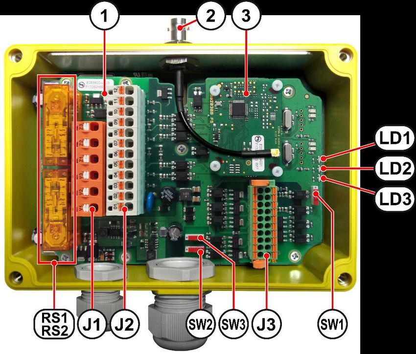
RSEF safety transmitter: terminal blocks
Check the SIM card is inserted inside the RSEF transmitter: as shown with the red circle, there is a dedicated slot located behind
the transmitter front cover.

Before any installation, it is highly advised to perform a quick test as described in the following section.

                                                                             Terminal Function                  Terminal Function
                                                                                                                         On / Restart
                                                                                 1        V- E.S.                  17
                                                                                                                         button input
                                                                                 2        V- E.S.
                                                                                 3        V+ E.S.                  18      Input No.9
                                                                                 4        V+ RSEF
                                                                                 5        V- RSEF                  19      Input No.7
                                                                                 6        V- RSEF                  20      Input No.5
                                                                                 7        E.S. contact 1           21      Input No.3
                                                                                 8        E.S. contact 2           22      Input No.1
                                                                                 9        E.S. mode                23      V- Input
                                                                                10        V+ E.S.                  24      Input No.10
                                                                                          Ind. light V2
                                                                                11                                 25      Input No.8
                                                                                          output
                                                                                          Ind. light V1
                                                                                12                                 26      Input No.6
                                                                                          output
                                                                                13        Not used                 27      Input No.4
                                                                                14        Not used                 28      Input No.2
                                                                                                                           0 V of module
                                                                                15        V- Inputs                29
                                                                                                                           VUB090
                                                                                                                           +5 VDC of
                                                                                16        V- Inputs                30
                                                                                                                           module VUB090

                                                                             Ind. light   Function
                                                                                V1        (GREEN) "On", "Radio transmission", "Diagnostic"
                                                                                V2        (RED) "Diagnostic"
                                                                                V3        (ORANGE) "Power supply"

                                                                                                       Doc. ref : 333130B_A006-EN
                                                                                                                                             2021/06/11

                                                                                                                                        Page 9 / 53
Transmitter test wiring (independent from any application)

This wiring is intended to test :   - a command input
                                    - and the « emergency stop » safety input

 •   Step 1        Prepare a stabilized power supply, 24VDC (+/- 20 %) 500 mA minimum

 •   Step 2        Wire the transmitter as follows :
                   •    Connect the +24VDC of the stabilized power supply to terminals 3 and 4
                   •    Connect the ground of the power supply to the 3 terminals 1 and 5 and 15 (ground ref. of inputs)
                   •    Connect an NC double contact emergency stop button to terminals 7, 8, 9 and 10.
                   •    Connect an NO button “Restart” across the +24VDC and terminal No. 17.
                   •    Connect an NO button simulating an input across the +24VDC and terminal No. 22 (E1).
                   •    Possibly, indicator lights giving the same indication as indicator lights V1 and V2 of the transmitter may
                        be connected to terminals 11 (V2) and 12 (V1) and 0V.

 •   Step 3        Switch on the auxiliary supply of the transmitter.

 •   Step 4        Activate the safety input (unlock Emergency stop).

 •   Step 5        Press on the Restart pushbutton in case of manual restart mode.
                   Indicator light V3 of the transmitter should come on steady, indicator light V1 should flash regularly (radio
                   transmission) and indicator light V2 should be off; if this indicator light flashes, there is an error: refer to the
                   error message table.

 •   Step 6        Switch off the supply to the transmitter.
                   Proceed as instructed in the following pages to wire the safety receiver RSRDevice.

                                                                                                Doc. ref : 333130B_A006-EN
                                                                                                                               2021/06/11

                                                                                                                          Page 10 / 53
RSRDevice safety receiver: terminal blocks
RS1&RS2 Safety relays J1 Terminal block : Safety outputs
1 Red indicator light: status of safety relays RS1 and RS2 Terminal Function
2 Antenna BNC / antenna extension connector Y1
1st safety output (NO contact)
Z3
3 Radio module
Y2
LD1 Yellow indicator light : Transceiver power supply OK 2nd safety output (NO contact)
Z2
LD2 Red indicator light: status of safety relays RS1 and RS2 Y3
3rd safety output (NO contact)
LD3 Green indicator light : Radio reception + Diagnostics Z1
J2 Terminal block : Safety inputs and power supply SW3/SW2 : Voltage reference for static outputs
Terminal Function Position “0”: based on RSRDevice power supply for
12 24VDC and 0V (terminals 01-02 on J2)
Input for Enabling Handle Detection
11 Position “1”: based on external voltage reference
10 V+ and V- (terminals 15-16 on J3)
Input 2 for Enabling Handle
09
08 SW1 : Operating mode
Input 1 for Enabling Handle
07
Position “1”: Normal operation (Diagnosis mode)
06
Input 2 for emergency stop or safety light curtain
05
Position “0”: Programming (Configuration mode)
04
Input 1 for emergency stop or safety light curtain
03
02 Power supply ( - ): 0V
01 Power supply (+): 24 VDC
J3 Terminal block : Communication, static sutputs and indicators
Function Terminals Function
RXD RS232 1 2 not used / not connected
TXD RS232 3 4 Configuration INPUT
GND 5 6 Configuration GND
Error message (red indicator light) + 7 8 - Error message (red indicator light)
Radio reception status (orange indicator light) + 9 10 - Radio reception status (orange indicator light)
Machine operating status (green indic. light) + 11 12 - Machine operating status (green indic. light)
Input for main contactor monitoring function 13 14 Input for main contactor monitoring function
Optional voltage reference for outputs (V+) 15 16 (V-) Optional voltage reference for outputs
Output nb.1 17 18 Output nb.2
Output nb.3 19 20 Output nb.4
Doc. ref : 333130B_A006-EN
2021/06/11
Page 11 / 53Assignment of RSEF inputs to RSRDevice static outputs
Assignment by default of RSRDevice
static outputs (J3 terminals)
17 18 19 20
E1 X
RSEF E2 X
inputs E3 X
E4 X
For any change in output assignements, please refer to section 3.2.1 related to RSRDevice software configuration
(10 inputs and several events can be assigned and combined onto the 4 ouputs of the receiver).
Voltage reference of RSRDevice static outputs
There are two options for the output voltage of the static outputs: it is possible to isolate all the outputs from the
RSRDevice auxiliary supply. In all cases, the maximum output current shall be 100 mA per output.
Isolated mode:
SW3 and SW2 must be in position “1”
A continuous auxiliary supply voltage must be applied between points 15-16 of J3.
This supply voltage must be between 5-30VDC (input 15: V+ / input16: V- / Insulation voltage: > 4400 VRMS)
Non isolated mode :
SW3 and SW2 must be in position “0”.
Terminal points 15-16 of J3 must be unconnected.
The voltage reference of the ouputs is identical to the power supply voltage of the RSRDevice receiver.
Receiver test wiring (independent from any application)
This wiring aims at testing a command output and an « emergency stop » safety input :
• Step 1 Prepare a stabilized power supply, 24VDC (+/- 20 %) 500 mA minimum
• Step 2 Wire the receiver as follows :
o Shunt the terminal pairs J2[03-04], J2[05-06] and J3[13-14]
o Connect the +24VDC of the stabilized power supply to terminals J2[1]
o Connect the ground of the power supply to the terminal J2[2]
• Step 3 Switch on the receiver power supply.
Yellow indicator light LD1 on the receiver comes on steady.
• Step 4 Switch off the receiver.
Perform the system test as detailed in the next section.
Doc. ref : 333130B_A006-EN
2021/06/11
Page 12 / 53Global system test before installation
• Step A Switch on the RSEF transmitter and the RSRDevice receiver
The RSRDevice receiver should be ready to receive the RSEF transmitter frame:
the indicator light LD1 comes on steady
the indicator light V3 on the transmitter RSEF comes on steady
• Step B Activate the safety input (unlock Emergency stop) on both devices
The RSEF transmitter should be ready to transmit:
the indicator light V1 should go off steadily.
• Step C On RSEF transmitter:
Press on the restart pushbutton (If the transmitter is in « manual » restart mode).
the indicator light V2 should blink.
On RSRDevice receiver:
The safety relays (RS1 and RS2) should engage.
the two indicator lights LD2 and LD3 should go off steadily.
• Step D Press the emergency stop pushbutton connected to the RSEF transmitter
The RSRDevice receiver safety relays should immediately be deactivated.
Doc. ref : 333130B_A006-EN
2021/06/11
Page 13 / 533 Modifying the product configuration
RSEF transmitter configuration
General process
The various settings on the transmitter RSEF are made using a DIP switch and a validation button located inside the transmitter.
Remove the front panel to access these components:
Doc. ref : 333130B_A006-EN
2021/06/11
Page 14 / 53Configuring the transmission channel
To limit accidental cut-outs due to radio interference, it is important to choose an available radio channel (frequency). This choice
is governed by the following principles:
➢ The receiver point of installation must be considered as the centre of the radio link,
➢ Estimate the maximum distance « D max » which there may be between the transmitter and the receiver,
➢ Identify the frequencies used for all the radio transmitters located within a radius of 2xD max.
➢ Chose a frequency which is as far as possible from those used by the nearest transmitters and which is not used by the
transmitters identified.
The procedure described below is used to modify the radio channel of the transmitter RSEF and receiver RSRDevice. The
receiver must be supplied throughout the channel modification procedure in order to receive the radio channel change command
from the transmitter RSEF.
1- Deactivate the safety input of the transmitter RSEF (1)
2- Select the new radio channel using DIP switches 1 to 6 (see correspondence table below)
3- Activate the safety input of the transmitter RSEF (2)
4- The 2 indicator lights V1-V2 flash to indicate the new radio channel being programmed :
- Indicator light V1 (GREEN) indicates the units (0 = off steady, 1 = 1 flash, 2 = 2 flashes, etc…)
- Indicator light V2 (RED) indicates the tens (0 = off, 10 = 1 flash, 20 = 2 flashes, etc…)
Example :
5- Once you have chosen the radio channel, press the validation button BPV
6- The two indicator lights, V1 and V2, flash simultaneously and the transmitter sends the receiver RSRDevice the
radio channel change command (this action takes around 20 s., then indicator lights V1 and V2 go off).
Note : If the validation button BPV has not been pressed, you can cancel the frequency change by repositioning the
DIP switches 1 to 6 to the initial radio channel code.
7- To exit the radio frequency setting modes, activate, then deactivate the safety input (1)(2).
8- If the transmitter is in « manual » restart mode, press the restart button wired to input 17
Notes :
If other settings are to be modified during this procedure (such as “inputs check” or “restart mode”),
they need to be modified and validated one by one.
(1) If an emergency stop pushbutton is wired on this input, the component must be locked.
(2) If an emergency stop pushbutton is wired on this input, the component must be unlocked.
Doc. ref : 333130B_A006-EN
2021/06/11
Page 15 / 53Radio channel programming table for 433-434 MHz range
Note : For the « extended range » version, only channels 41 to 64 are accessible.
Freq. DIP switch position Freq. DIP switch position
Chan. Chan.
(MHz) 1 2 3 4 5 6 (MHz) 1 2 3 4 5 6
01 433,100 OFF OFF OFF OFF OFF OFF 33 433,900 OFF OFF OFF OFF OFF ON
02 433,125 ON OFF OFF OFF OFF OFF 34 433,925 ON OFF OFF OFF OFF ON
03 433,150 OFF ON OFF OFF OFF OFF 35 433,950 OFF ON OFF OFF OFF ON
04 433,175 ON ON OFF OFF OFF OFF 36 433,975 ON ON OFF OFF OFF ON
05 433,200 OFF OFF ON OFF OFF OFF 37 434,000 OFF OFF ON OFF OFF ON
06 433,225 ON OFF ON OFF OFF OFF 38 434,025 ON OFF ON OFF OFF ON
07 433,250 OFF ON ON OFF OFF OFF 39 434,050 OFF ON ON OFF OFF ON
08 433,275 ON ON ON OFF OFF OFF 40 434,075 ON ON ON OFF OFF ON
09 433,300 OFF OFF OFF ON OFF OFF 41 434,100 OFF OFF OFF ON OFF ON
10 433,325 ON OFF OFF ON OFF OFF 42 434,125 ON OFF OFF ON OFF ON
11 433,350 OFF ON OFF ON OFF OFF 43 434,150 OFF ON OFF ON OFF ON
12 433,375 ON ON OFF ON OFF OFF 44 434,175 ON ON OFF ON OFF ON
13 433,400 OFF OFF ON ON OFF OFF 45 434,200 OFF OFF ON ON OFF ON
14 433,425 ON OFF ON ON OFF OFF 46 434,225 ON OFF ON ON OFF ON
15 433,450 OFF ON ON ON OFF OFF 47 434,250 OFF ON ON ON OFF ON
16 433,475 ON ON ON ON OFF OFF 48 434,275 ON ON ON ON OFF ON
17 433,500 OFF OFF OFF OFF ON OFF 49 434,300 OFF OFF OFF OFF ON ON
18 433,525 ON OFF OFF OFF ON OFF 50 434,325 ON OFF OFF OFF ON ON
19 433,550 OFF ON OFF OFF ON OFF 51 434,350 OFF ON OFF OFF ON ON
20 433,575 ON ON OFF OFF ON OFF 52 434,375 ON ON OFF OFF ON ON
21 433,600 OFF OFF ON OFF ON OFF 53 434,400 OFF OFF ON OFF ON ON
22 433,625 ON OFF ON OFF ON OFF 54 434,425 ON OFF ON OFF ON ON
23 433,650 OFF ON ON OFF ON OFF 55 434,450 OFF ON ON OFF ON ON
24 433,675 ON ON ON OFF ON OFF 56 434,475 ON ON ON OFF ON ON
25 433,700 OFF OFF OFF ON ON OFF 57 434,500 OFF OFF OFF ON ON ON
26 433,725 ON OFF OFF ON ON OFF 58 434,525 ON OFF OFF ON ON ON
27 433,750 OFF ON OFF ON ON OFF 59 434,550 OFF ON OFF ON ON ON
28 433,775 ON ON OFF ON ON OFF 60 434,575 ON ON OFF ON ON ON
29 433,800 OFF OFF ON ON ON OFF 61 434,600 OFF OFF ON ON ON ON
30 433,825 ON OFF ON ON ON OFF 62 434,625 ON OFF ON ON ON ON
31 433,850 OFF ON ON ON ON OFF 63 434,650 OFF ON ON ON ON ON
32 433,875 ON ON ON ON ON OFF 64 434,675 ON ON ON ON ON ON
Radio channel programming table for 911-918 MHz range
Freq. DIP switch position Freq. DIP switch position
Chan. Chan.
(MHz) 1 2 3 4 5 6 (MHz) 1 2 3 4 5 6
01 911,800 OFF OFF OFF OFF OFF OFF 33 915,100 OFF OFF OFF OFF OFF ON
02 911,900 ON OFF OFF OFF OFF OFF 34 915,200 ON OFF OFF OFF OFF ON
03 912,000 OFF ON OFF OFF OFF OFF 35 915,300 OFF ON OFF OFF OFF ON
04 912,100 ON ON OFF OFF OFF OFF 36 915,400 ON ON OFF OFF OFF ON
05 912,200 OFF OFF ON OFF OFF OFF 37 915,500 OFF OFF ON OFF OFF ON
06 912,300 ON OFF ON OFF OFF OFF 38 915,600 ON OFF ON OFF OFF ON
07 912,400 OFF ON ON OFF OFF OFF 39 915,700 OFF ON ON OFF OFF ON
08 912,500 ON ON ON OFF OFF OFF 40 915,800 ON ON ON OFF OFF ON
09 912,600 OFF OFF OFF ON OFF OFF 41 915,900 OFF OFF OFF ON OFF ON
10 912,700 ON OFF OFF ON OFF OFF 42 916,000 ON OFF OFF ON OFF ON
11 912,800 OFF ON OFF ON OFF OFF 43 916,100 OFF ON OFF ON OFF ON
12 912,900 ON ON OFF ON OFF OFF 44 916,200 ON ON OFF ON OFF ON
13 913,000 OFF OFF ON ON OFF OFF 45 916,300 OFF OFF ON ON OFF ON
14 913,100 ON OFF ON ON OFF OFF 46 916,400 ON OFF ON ON OFF ON
15 913,200 OFF ON ON ON OFF OFF 47 916,500 OFF ON ON ON OFF ON
16 913,300 ON ON ON ON OFF OFF 48 916,600 ON ON ON ON OFF ON
17 913,400 OFF OFF OFF OFF ON OFF 49 916,700 OFF OFF OFF OFF ON ON
18 913,500 ON OFF OFF OFF ON OFF 50 916,800 ON OFF OFF OFF ON ON
19 913,600 OFF ON OFF OFF ON OFF 51 916,900 OFF ON OFF OFF ON ON
20 913,700 ON ON OFF OFF ON OFF 52 917,000 ON ON OFF OFF ON ON
21 913,800 OFF OFF ON OFF ON OFF 53 917,100 OFF OFF ON OFF ON ON
22 913,900 ON OFF ON OFF ON OFF 54 917,200 ON OFF ON OFF ON ON
23 914,000 OFF ON ON OFF ON OFF 55 917,300 OFF ON ON OFF ON ON
24 914,100 ON ON ON OFF ON OFF 56 917,400 ON ON ON OFF ON ON
25 914,300 OFF OFF OFF ON ON OFF 57 917,500 OFF OFF OFF ON ON ON
26 914,400 ON OFF OFF ON ON OFF 58 917,600 ON OFF OFF ON ON ON
27 914,500 OFF ON OFF ON ON OFF 59 917,700 OFF ON OFF ON ON ON
28 914,600 ON ON OFF ON ON OFF 60 917,800 ON ON OFF ON ON ON
29 914,700 OFF OFF ON ON ON OFF 61 917,900 OFF OFF ON ON ON ON
30 914,800 ON OFF ON ON ON OFF 62 918,000 ON OFF ON ON ON ON
31 914,900 OFF ON ON ON ON OFF 63 918,100 OFF ON ON ON ON ON
32 915,000 ON ON ON ON ON OFF 64 918,200 ON ON ON ON ON ON
Doc. ref : 333130B_A006-EN
2021/06/11
Page 16 / 53Radio channel programming table for 869 MHz range
Freq. DIP switch position
Chan
(MHz) 1 2 3 4 5 6
01 869,7125 OFF OFF OFF OFF OFF OFF
02 869,7375 ON OFF OFF OFF OFF OFF
03 869,7625 OFF ON OFF OFF OFF OFF
04 869,7875 ON ON OFF OFF OFF OFF
05 869,8125 OFF OFF ON OFF OFF OFF
06 869,8375 ON OFF ON OFF OFF OFF
07 869,8625 OFF ON ON OFF OFF OFF
08 869,8875 ON ON ON OFF OFF OFF
09 869,9125 OFF OFF OFF ON OFF OFF
10 869,9375 ON OFF OFF ON OFF OFF
11 869,9625 OFF ON OFF ON OFF OFF
12 869,9875 ON ON OFF ON OFF OFF
5mW (7dBm)
Radio channel programming table for 920 MHz range
Freq. DIP switch position Freq. DIP switch position
Chan Chan
(MHz) 1 2 3 4 5 65 (MHz) 1 2 3 4 5 65
16 928.15 ON ON ON ON OFF ON
01 920,6 OFF OFF OFF OFF OFF ON
17 928.25 OFF OFF OFF OFF ON ON
02 920,8 ON OFF OFF OFF OFF ON 18 928.35 ON OFF OFF OFF ON ON
03 921.0 OFF ON OFF OFF OFF ON 19 928.45 OFF ON OFF OFF ON ON
04 921.2 ON ON OFF OFF OFF ON 20 928.55 ON ON OFF OFF ON ON
05 921,4 OFF OFF ON OFF OFF ON 21 928.65 OFF OFF ON OFF ON ON
06 921,6 ON OFF ON OFF OFF ON 22 928.75 ON OFF ON OFF ON ON
07 921,8 OFF ON ON OFF OFF ON 23 928.85 OFF ON ON OFF ON ON
08 922.0 ON ON ON OFF OFF ON 24 928.95 ON ON ON OFF ON ON
09 922.2 OFF OFF OFF ON OFF ON 25 929.05 OFF OFF OFF ON ON ON
10 922.4 ON OFF OFF ON OFF ON 26 929.15 ON OFF OFF ON ON ON
11 922.6 OFF ON OFF ON OFF ON 27 929.25 OFF ON OFF ON ON ON
12 922.8 ON ON OFF ON OFF ON 28 929.35 ON ON OFF ON ON ON
13 923.0 OFF OFF ON ON OFF ON 29 929.45 OFF OFF ON ON ON ON
14 923.2 ON OFF ON ON OFF ON 30 929.55 ON OFF ON ON ON ON
15 923.4 OFF ON ON ON OFF ON 31 929.65 OFF ON ON ON ON ON
20mW (13dBm) 1mW (0dBm)
Channel transmission operating mode :
• Radio transmission mode for channels 01 to 15 (20 mW) :
- A strict frequency plan must be put in place to ensure that the chosen channel is available.
- Each transmission cycle consists of 3 phases :
- listening phase: the selected channel must be free of any signal for 5 ms before starting the transmission phase. In case it is
busy, the transmitter keeps on listening until the channel happens to be free for 5 ms.
After 300 ms without transmission possibility, the red led V2 will be activated for information, but the system keeps on listening
until the channel is free for 5 ms.
It is necessary to press the white validation button for 4 seconds to reset red led V2 (or switch off/on the transmitter)
- 4-second transmission phase: normal transmission of radio frames.
- 50-ms pause phase: no radio function at all during 50 ms prior to listening phase.
• Radio transmission mode for channels 16 to 31 (1 mW) :
- A frequency plan remains recommended for all radio applications.
- The safety signal is emitted approximately every 100 ms, for a duration of approximately 50 ms.
- The analysis of the quality of the radio signal shows a value close to 50% corresponding to the 50% duty cycle: the signal
must not be polluted by third party sources.
- If it is necessary to go beyond the range of the RSEF transmitter, the use of a JUMP repeater will be carried out with
additional synchronization to the initial duty cycle.
Configuring the check function for inputs E1 to E10 on power up
This function is used to check the status of the contacts of the inputs on power up of the transmitter RSEF. If a contact is « closed»
on power up, the transmitter will indicate an error by indicator lights V1 and V2 (4 flashes).
5 DIP Switch 6 always on « ON » position
Doc. ref : 333130B_A006-EN
2021/06/11
Page 17 / 53This function can be activated using DIP switch No. 7.
1- Deactivate the safety input of the transmitter RSEF (1)
2- Activate or deactivate the input check function using DIP switch No. 7 :
3- Activate the safety input of the transmitter RSEF (2) ; the two indicator lights, V1 and V2, flash alternately to indicate
the system is on standby for validation.
4- Press the validation button BPV ; indicator lights V1 and V2 go off.
5- To exit this configuration mode, deactivate, then activate the safety input (1)(2).
6- If the transmitter is in « manual » restart mode, press the restart button wired to input 17
(1) If an emergency stop pushbutton is wired on this input, the component must be locked.
(2) If an emergency stop pushbutton is wired on this input, the component must be unlocked.
Example of fault on input No. 3 (NO contact faulty) :
Note :
If other settings are to be modified during this procedure (such as “inputs check” or “restart mode”),
they need to be modified and validated one by one.
Doc. ref : 333130B_A006-EN
2021/06/11
Page 18 / 53Configuring the restart mode of RSEF transmitter
This function defines the restart mode of safety transmitter (activation of the radio transmission) after a stop caused by deactivation
of its safety input (i.e.: emergency stop button pressed) or cut of its power supply.
◼ « Manual » restart mode :
The safety transmitter is manually restarted (radio transmission activated) by pressing on a « Restart » pushbutton
following deactivation and activation of its safety input.
◼ « Automatic » restart mode :
The safety transmitter is automatically restarted (radio transmission activated) following deactivation and activation of its
safety input.
IMPORTANT : Do not connect a restart button in this mode (input nb.17 not connected).
This function is configured using DIP switch No. 8
1- Deactivate the safety input of the transmitter RSEF (1)
2- Using DIP switch No. 8, select the transmitter restart mode : « Automatic » or « Manual » :
3- Activate the safety input of the transmitter RSEF (2) ; the two indicator lights, V1 and V2, flash alternately to indicate the
system is on standby for validation.
4- Press the validation button (BPV) ; indicator lights V1 and V2 go off.
5- To exit this configuration mode, deactivate, then activate the safety input (1)(2).
(1) If an emergency stop pushbutton is wired on this input, the component must be locked.
(2) If an emergency stop pushbutton is wired on this input, the component must be unlocked.
Wiring diagram with restart button (« manual » restart mode) :
In the event of deactivation followed by activation of the safety input (emergency stop, for example), the transmitter will only be
able to transmit provided the « restart » pushbutton has been pressed.
Note :
If the other setting has also been modified during this procedure (as “Radio channel number” or “restart mode”), each
modified setting have to be performed one by one.
Doc. ref : 333130B_A006-EN
2021/06/11
Page 19 / 53RSRDevice receiver configuration
General principle
The RSRDevice receiver can be set onto one of two following operating modes:
- Programming mode or Configuration mode this mode triggers the opening of the safety relays
- Receiving mode or Diagnosis mode this mode is used for normal operations
To change the operating modes there are two possibilities:
- use the physical switch SW1 switch SW1 up for normal operations
- use the configuration input (4-6/J3) deactivate this input for normal operations
When the RSRDevice receiver is set to Programming mode, the serial link terminals 1-3-5 on J3 terminal block allows you
to configure the RSRDevice receiver. There are two ways of programming your RSRDevices:
- with direct RS232 instructions use normal RS232 cable to any controller or PLC
- with the help of DialogRSRDevice software use dedicated RSW39 cable to a laptop/PC
Additional support and documentations are available:
- RS232 protocol instructions please refer to JAY Electronique
- DialogRSRDevice software guidelines please refer to JAY Electronique
The dedicated programming software DialogRSRDevice, is available on JAY Electronique website. The use of such software
is protected by a password. Passwords, or RS232 protocol instructions, are only delivered to “level 2” skilled person
(a person who was trained by JAY Electronique, and who was authorized to modify RSRDevice receiver parameters).
Safety delay
The “Safety delay” allows you to generate a delay before the deactivation of the safety relays RS1 and RS2.
The purpose of this timer is:
- to indicate a system stop to the equipment so as to manage an action before the complete shutdown
- to keep an immediate start of the safety stop process (to be executed by at the end of the delay)
This timer is activated after an emergency stop signal from the RSEF transmitter and also, after a passive stop (radio loss).
Total Tripping time = Active stop time or Passive stop time + Safety delay
This timer is not taken into account in the folowwing cases :
• during a local emergency stop (stop pushbutton wired to receiver RSRDevice J2-03,04,05,06),
• when using a wired enabling handle (connected to receiver RSRDevice J2-07,08,09,10,11,12)
• when a system error appears
This timer can be set to a value from 0 to 10s (steps of 1s) in Programming mode (see previous section)
IMPORTANT: According to Machinery Directive section 4.1.1(EN ISO 13850:2015), all time delays must be
determined by the risk assessment of the machine. Please also refer to IEC 60204-1 :2005, 9.2.5.4.2.
Doc. ref : 333130B_A006-EN
2021/06/11
Page 20 / 534 Wiring the components
Wiring the RSEF transmitter
NOTE 1: See description of all terminals in section 2.2.
NOTE 2: See correspondence between inputs of transmitter RSEF and outputs of receiver RSRDevice in section 2.4.1.
Typical wiring diagram
with emergency stop pushbutton connected to safety input and 10 dry-contact inputs (No pushbuttons).
Example connection of a safety light curtain on transmitter safety input
Example with static inputs (PLC for example)
Doc. ref : 333130B_A006-EN
2021/06/11
Page 21 / 53Wiring the RSRDevice receiver
NOTE 1 : See description of all terminals in section 2.4.
NOTE 2 : See correspondence between inputs of transmitter RSEF and outputs of receiver RSRDevice in section 2.4.1.
CAUTION : The loads connected to the receiver outputs must not consume more than 100 mA with 24VDC.
Multi-strand wires: use of wire end ferrules is mandatory
Where flexible multi-strand wires are used, wire end ferrules must be used to avoid false contacts
and short-circuits.
Conductor wire sections to be observed
Be sure to observe the min. /max. wire sections listed below for electrical connection an Terminal
blocks :
J1 & J2 0,50 mm² to 1,5 mm²
J3 0,25 mm² to 1,5 mm²
USA/Canada specifications for installation and conductor wires to be used
• Particularity for a wall installation: A code inspector will allow a cord if it is not a long run and
not likely to be damaged. It may be required to remove the cord and install conduit if the
installation is under these clauses.
• The circuit breaker supplying the RSRDevice must be accessible and close to the
RSRDevice.
• The type of wires used for wiring the J1 Terminal block (Safety relay outputs), is
mandatory: class 1 size 18AWG with min temperature range -25°C to +60°C.
• Maximum switching voltage : 30 V rms, 42.4 V peak, or 60 V dc according to UL61010-1 3rd
edition: 2012
Doc. ref : 333130B_A006-EN
2021/06/11
Page 22 / 53Operation of safety relays RS1-RS2 of RSRDevice receiver
Interruption of the safety stop chain is ensured by safety relays RS1 and RS2 (internal to receiver RSRDevice) which control
the contacts accessible by terminals Y1-Z3, Y2-Z2 and Y3-Z1.
The state of relays RS1 and RS2 depends on :
▪ the safety input of the transmitter RSEF ,
▪ the safety input of the receiver RSRDevice (a),
▪ possible faults detected,
▪ Possible loss of radio link.
▪ Possible loss of power supply of safety transmitter or safety receiver.
▪ Possible enabling handle status (b)
(a)= An external safety stop device can be connected, such as an emergency stop pushbutton, or a gate control device wired to the inputs
provided for this purpose on the receiver (connection terminals J2 03-04 / J2 05-06). The state of these inputs will act directly on relays
RS1 and RS2.
(b)= An enabling handle can be wired to the inputs provided for this purpose on the receiver (connection terminals J2 07-08 / J2 09-10 and
J2-11-12). The state of these inputs will act directly on relays RS1 and RS2 and change the receiver operating mode, see section 4.2.6.
Monitoring of main contactors
The input connected to terminals J3 13-14 is used to monitor the state of the contactor(s) connected to the RS1-RS2 safety
outputs.
The state of the contactor(s) contact(s) wired on this input must be closed in order to start the RSRDevice receiver.
IMPORTANT : This monitoring depends on the safety performance level required by the machine.
Enabling handle : Wiring and operating mode
IMPORTANT : The enabling handle must comply with the requirements
of 60947-5-1:2004/A1:2009, EN ISO12100 and EN 60204-1:2016 standards.
The receiver RSRDevice is provided with six inputs dedicated to the wiring of an enabling handle.
In the case of enabling handle use, four of these inputs will be used for the connection of the double channel enabling device.
The two other inputs will be used for detection of the enabling switch.
The wireless safety stop function is overwritten by using a dual channel enabling switch.
When the enabling handle is detected, the receiver will reset and the Radio is disabled (The enabling handle has higher
priority than the radio mode)
The enabling handle has lower priority than the local emergency stop.
In the event of a faulty enabling device, the safety output relays shall be immediately deactivated.
Doc. ref : 333130B_A006-EN
2021/06/11
Page 23 / 53Typical wiring diagram for RSRDevice receiver
Example with wired emergency stop button
IMPORTANT : The emergency stop pusbutton must comply with the requirements
of EN 60947-5-5:2016 and EN 60204-1:2016 standards.
Doc. ref : 333130B_A006-EN
2021/06/11
Page 24 / 53Example with a wired enabling handle
IMPORTANT : The enabling handle must comply with
the requirements of 60947-5-1:2004/A1:2009,
EN ISO12100 and EN 60204-1:2016 standards.
Example with the contactor monitoring function
Wiring an beacon light column
A beacon light column should be wired to the receiver. The column will indicate the status of the equipment monitored and
of the receiver RSRDevice. The indicator light status sheet should be fastened near to the indicator light column (Example
given in last page of this user manual).
The consumption of each indicator light of the column must not exceed 100 mA with 24VDC. Should this be the case, the
indicator lights must be controlled by auxiliary relays.
IMPORTANT : a standard indicator light column does not provide a safe information
(correct operation of lights is not certified)
light On steady Flashing Off
Red indicator lights flash a
specific number of times in the
Red Equipment stopped Equipment operating
event of a receiver malfunction
(see section 7.2)
active radio link between
Orange / /
transmitter and receiver
Green Equipment operating / Equipment stopped
Doc. ref : 333130B_A006-EN
2021/06/11
Page 25 / 535 Instructions for safe installation and commissioning
General information
Experience has shown that functional reliability basically depends on :
• the quality of the electrical power supply and protection systems,
• the characteristics of the components connected to the transmitter and receiver,
• the position of the transmission and reception antennas,
• The configuration and wiring of the various components.
RSEF transmitter
The installer shall:
• Install the product near the control area.
• Provide, if necessary, a location for a transmitter restart button in order to start the transmitter following a malfunction
or following an emergency stop condition.
• Connect a 0.5 amp delay-action fuse protection device in series on input Vin No. 4 (24V DC) of the transmitter.
• Familiarise yourself with all the characteristics given in the « technical characteristics » appendix.
RSRDevice receiver
The installer shall:
• Respect the sections and characteristics of the cables to be used, see the « technical characteristics » appendix
• Wire a cabled emergency stop device on the front panel of the unit.
• Secure, on the top of the unit, a 3-color indicator light column (green, orange, red) to indicate the operating status of
the system.
• Fasten, near the indicator light column, a colour code sheet showing the meaning of the indicator light statuses
(Example given in last page of this user manual).
• Connect a 250V/0.5 amp delay-action fuse protection device in series on input J2-01 (24V DC) of the receiver.
• Familiarise yourself with all the characteristics given in the « technical characteristics » appendix.
Doc. ref : 333130B_A006-EN
2021/06/11
Page 26 / 53Positioning the components and antennas
Please follow recommendations of installation of the antenna to obtain the best radio signal.
• When installing multiple transmitters side by side, the respective radio transmission antennas should be spaced
70cm at least.
• If a metal electrical housing is used, the antenna should be remote-mounted on the top of the housing.
• If a plastic housing is used, the antenna can be connected directly on the product using the BNC elbow supplied.
• Under no circumstances, the receiver RSRDevice shall be positioned with its electronic components facing down.
• The receiver RSRDevice must be installed on a rigid frame (min. 3 mm thick sheet metal) fastened with 4 M5
screws in the recesses of the housing provided for this purpose.
• If poor radiowave propagation is observed, for example : closed area, the antenna should be remote-mounted.
See installation instructions:
IMPORTANT : Do not remove the plastic insulating washer placed between the nut and the BNC connector mounted on the
bracket of antenna extension.
Doc. ref : 333130B_A006-EN
2021/06/11
Page 27 / 536 Optional radio components
Radio Frequency switch (ref. VUB090)
The RF switch is an optional component for RSEF with sales reference RSEF** - 1
This optional component avoids radio signal cancellation even in clear sight environments, for example due to
background reflections. It also ensures continuous radio link in congested RF environments, where signal reflections
and shadow zones are more common, by transmitting radio waves from two separate antennas alternatively.
The RSEF** - 1 transmitter is fitted with 2 extra outputs, terminals 29 and 30, which deliver the power supply to the
RF switch as well as the TTL output (terminal 14) to control the RF switch. See wiring diagram here below.
IMPORTANT :
The total length of coaxial cables connected to RSEF, with those on RF switch, shall not exceed 30m.
Grey
Black Red
RSEF terminal RF switch connection Cable color
14 TTL
29 0V
Please refer to label on the product
for wiring
30 +5 VDC
RF Signal COM
JUMP repeater and RF switch (ref. VUB095)
In situations where radio performance must be extended to cover a greater distance, a greater area, a new building hall,
a new warehouse aisle, or whenever heavy obstacles are met, etc, the JUMP radio repeater provides a solution to
guarantee the proper transmission of a radio safety signal (initially emitted by a JAY mono-directional product).
RSEF and RSRDevice are compatible with JUMP, which is compatible with the optional RF switch (ref VUB095)
Please refer to JUMP documentation for specific details
Doc. ref : 333130B_A006-EN
2021/06/11
Page 28 / 53Antennas for 433-434 MHz band
Antenna reference: VUA001A (supplied by default)
Type: straight, 1/4 wave, BNC connection
Approximate length: 190mm
Antenna reference: VUA002A
Type: straight, 1/2 wave, BNC connection
Approximate length: 335mm
Antenna references:
• VUA100AH (with 0,5m cable), VUA102AH (with 2m cable),
VUA105AH (with 5m cable), VUA110AH (with 10m cable)
Type: through insulated remote, 1/2 wave, BNC connection
Approximate length: 320mm / Required drill hole: 15mm
Antenna references:
• VUA103AM (with 3m cable), VUA105AM (with 5m cable)
Type: insulated magnetic remote, tuned, BNC connection
Approximate length: 440mm
Antenna references:
• VUA103AV (with 3m cable),VUA105AV (with 5m cable)
Type: through uninsulated remote, 1/4 wave, BNC connection
Approximate length: 180mm / Required drill hole: 12mm or 19mm
Antenna reference: VUA102CP
Type: flat and circular, 2-m long coaxial cable with BNC connector
Size: 45mm by 15mm / Required drill hole: 12mm
(for mounting on metallic structures, it is advised to add an insulating gasket
between the thightening nut and the metallic structure)
Antennas for 869, 911-918 MHz band
Antenna reference: VUA001B (supplied by default) 860-920 MHz
Type: straight, 1/4 wave, BNC connection
Approximate length: 90mm
Antenna reference: VUA002B 820-960 MHz
Type: straight, 1/2 wave, BNC connection
Approximate length: 200mm
Antenna references: 860-960 MHz
• VUA100BH (with 0,5m cable), VUA102BH (with 2m cable),
VUA105BH (with 5m cable), VUA110BH (with 10m cable)
Type: through insulated remote, 1/2 wave, BNC connection
Approximate length: 190mm / Required drill hole: 15mm
Antenna references: 820-960 MHz
• VUA103BM (with 3m cable), VUA105BM (with 5m cable)
Type: insulated magnetic remote, tuned, BNC connection
Approximate length: 320mm
Antenna references: 900-920 MHz
• VUA103BV (with 3m cable),VUA105BV (with 5m cable)
Type: through uninsulated remote, 1/4 wave, BNC connection
Approximate length: 100mm / Required drill hole: 12mm or 19mm
Doc. ref : 333130B_A006-EN
2021/06/11
Page 29 / 53Antennas for 920 MHz band
Antenna reference: VUA001B (supplied by default) 860-920 MHz
Type: straight, 1/4 wave, BNC connection
Approximate length: 90mm
Antenna reference: VUA002B 820-960 MHz
Type: straight, 1/2 wave, BNC connection
Approximate length: 200mm
Antenna references: 860-960 MHz
• VUA100BH (with 0,5m cable), VUA102BH (with 2m cable),
VUA105BH (with 5m cable), VUA110BH (with 10m cable)
Type: through insulated remote, 1/2 wave, BNC connection
Approximate length: 190mm / Required drill hole: 15mm
Antenna references: 820-960 MHz
• VUA103BM (with 3m cable), VUA105BM (with 5m cable)
Type: insulated magnetic remote, tuned, BNC connection
Approximate length: 320mm
Antenna references: 900-920 MHz
• VUA103BV (with 3m cable),VUA105BV (with 5m cable)
Type: through uninsulated remote, 1/4 wave, BNC connection
Approximate length: 100mm / Required drill hole: 12mm or 19mm
Antenna references: 700-960 MHz
• VUA102BP (with 2,5m de cable)
Type : flat and circular, with BNC connexion
Size : 80mm x 23mm x 10mm / Required drill hole : 17,5mm
(Gain 2 dBi)
Doc. ref : 333130B_A006-EN
2021/06/11
Page 30 / 537 Troubleshooting, Maintenance, Warranty
Diagnosis - RSEF transmitter
Messages given by indicator lights V1 and V2
To determine possible faults, the transmitter has two indicator lights on the front panel, V1 and V2.
Normal operation :
V1 V2 Message indicated by
Transmitter status Action
(green) (red) indicator lights
ON for 1 second,
After transmitter power up OFF Transmitter initialisation phase /
then OFF
On “manual” restart mode, after
On standby for action on
transmitter power up or after - Press restart button to place transmitter
ON OFF restart button (restart mode
deactivation/activation of safety in radio transmission mode
programmed for « manual »)
input
After transmitter power up or
when restart button is pressed
Flash OFF RADIO transmission /
(restart function in « auto »
mode)
Flashes indicate Flashes indicate
Radio channel number
number of units of number of tens of /
In radio channel configuration indication
new radio channel new radio channel
mode
Channel inaccessible with
2 flashes 2 flashes Change radio channel (40 to 64)
10mW
Abnormal operation :
Transmitter V1 V2 V3 Message indicated by
Solution
status (green) (red) (orange) indicator lights
After transmitter Power supply problem, - Check power supply voltage
OFF OFF OFF
power up transmitter not supplied - Check condition of protection fuse
- SIM card not present,
- SIM card incorrectly inserted or removed from its
SIM card read error
location
OFF OFF ON - SIM card faulty (must be replaced)
After transmitter Check the wiring of safety input between terminals
Incorrect wiring of safety input
power up Nb. 7 and Nb. 10.
Check the transmitter wiring : NO contacts of inputs
Or « Input check » function has
4 flashes 4 flashes ON (nb 1 to nb 10) and restart button must be in «idle»
detected an error
position when transmitter is powered up.
after activation of Power failure or faulty - check the supply voltage
safety input 6 flashes 6 flashes ON
emergency stop button - check the security entrance
5 flashes 5 flashes ON
Configuration DIP switches
changed see section 3.1
Alternate flashes ON
Doc. ref : 333130B_A006-EN
2021/06/11
Page 31 / 53Diagnosis - RSRDevice receiver
Error messages are given by the indicator light (RED color on indicator light column) connected to 07-08/J3 terminals.
This indicator light blinks a specific number of times in the event of a receiver malfunction:
number of
Message Solution
blinking
If the error persists after restarting the system,
1 Error on MCUs: Miscellaneous electronic fault
please contact our customer service
Requires a factory return of the product, please
2 Error on MCUs: RAM
contact our customer service
Requires a factory return of the product, please
3 Error on MCUs: ROM
contact our customer service
4 Error on MCUs: Parameters Check the configuration using dedicated software*
This error can occur after a system shutdown.
5 Error on MCUs: Link with MCU no2 If the problem persists after a reboot, please
contact our customer service
Requires a factory return of the product, please
6 Error on MCUs: EEPROM
contact our customer service
7 Error on MCUs: LOW VOLTAGE Check power supply
Requires a factory return of the product, please
8 Error on MCUs: RADIO
contact our customer service
This error can occur after a system shutdown.
9 Error on MCUs: Safety relay If the problem persists after a reboot, please
contact our customer service
Every
Wired emergency stop button activated (pressed) Unlock the emergency stop button
second
Repeat a complete emergency stop cycle to clear
the error.
Fast blinks Error detected on wired emergency stop button
If the error appears again, check the wiring and the
emergency stop button.
* The dedicated programming software “DialogRSRDevice” is available on JAY Electronique website. The use of this
programming software is protected by a password, this password is only delivered to a skilled person “level 2” (a person who
was trained by JAY Electronique, and who is authorized to modify RSRDevice receiver parameters).
Connect the RSRDevice to a PC
The link between a PC and a RSRDevice is made via a serial COM port RS232. You can connect directly the COM port to
RSRDevice or use a RSW39 tool.
The RSW39 tool is a USB to RS232 Serial Converter. This cable requires USB drivers (available free of charge from JAY
Electronique or from http://www.ftdichip.com). The drivers are used to create a virtual COM port (VCP). This then allows the
user to communicate with the USB interface via a standard PC serial emulation port.
The serial emulation port created can be configured in the dedicated software “DialogRSRDevice” (separate documentation)
1800mm
Yellow
Orange
Black
J3
Doc. ref : 333130B_A006-EN
2021/06/11
Page 32 / 53Servicing
IMPORTANT : MAKE SURE TRANSMITTER AND RECEIVER POWER SUPPLIES ARE SWITCHED OFF
BEFORE YOU PERFORM ANY SERVICING OPERATION
• The components can only be disassembled by a trained technician in a “controlled” environment; parts must only be
replaced by genuine identical spare parts.
• Use only soap-based solutions when cleaning housings; do not use any aggressive cleaning products.
Replacement of RSEF transmitter
Without unwiring the product, proceed as detailed below :
1- Switch off the power supply
2- Remove the front panel from the product (Fig.1)
3- Transmitter RSEF : If the SIM card of the new transmitter does not contain the same information as the SIM card of
the defective product, remove the SIM card and install it in the new product. (Fig.2)
4- Disconnect the removable terminals by applying a turning action using a flat tip screwdriver (Fig.3)
5- Re-program the new product identically to the old product (Fig.4)
➢ DIP switches set identically for transmitter
6- Connect the removable terminals on the new product (Fig.5).
7- Connect and supply the new product and proceed with tests.
Doc. ref : 333130B_A006-EN
2021/06/11
Page 33 / 53You can also read