Plug-in tubes allow tunable oil removal, droplet packing, and reaction incubation for time-controlled droplet-based assays
←
→
Page content transcription
If your browser does not render page correctly, please read the page content below
Plug-in tubes allow tunable oil removal,
droplet packing, and reaction incubation for
time-controlled droplet-based assays
Cite as: Biomicrofluidics 15, 024108 (2021); https://doi.org/10.1063/5.0047924
Submitted: 17 February 2021 . Accepted: 20 March 2021 . Published Online: 05 April 2021

  Meng Sun,         Gembu Maryu,    Shiyuan Wang,       Qiong Yang, and   Ryan C. Bailey

ARTICLES YOU MAY BE INTERESTED IN

A low-cost 3D printed microfluidic bioreactor and imaging chamber for live-organoid imaging
Biomicrofluidics 15, 024105 (2021); https://doi.org/10.1063/5.0041027

Accomplishment of one-step specific PCR and evaluated SELEX process by a dual-
microfluidic amplified system
Biomicrofluidics 15, 024107 (2021); https://doi.org/10.1063/5.0045965

Automated calibration of 3D-printed microfluidic devices based on computer vision
Biomicrofluidics 15, 024102 (2021); https://doi.org/10.1063/5.0037274

Biomicrofluidics 15, 024108 (2021); https://doi.org/10.1063/5.0047924                      15, 024108

© 2021 Author(s).
Biomicrofluidics                                                                                 ARTICLE           scitation.org/journal/bmf

    Plug-in tubes allow tunable oil removal,
    droplet packing, and reaction incubation
    for time-controlled droplet-based assays
    Cite as: Biomicrofluidics 15, 024108 (2021); doi: 10.1063/5.0047924
    Submitted: 17 February 2021 · Accepted: 20 March 2021 ·                                                            View Online   Export Citation    CrossMark
    Published Online: 5 April 2021

    Meng Sun,1,2            Gembu Maryu,1              Shiyuan Wang,1     Qiong Yang,1,a)      and Ryan C. Bailey2,a)

    AFFILIATIONS
    1
        Department of Biophysics, University of Michigan, Ann Arbor, Michigan 48109, USA
    2
        Department of Chemistry, University of Michigan, Ann Arbor, Michigan 48109, USA

    a)
        Authors to whom correspondence should be addressed: qiongy@umich.edu and ryancb@umich.edu

    ABSTRACT
    Here, we report a unique microfluidic technique that utilizes a membrane filter and plug-in tubes to remove oil and pack water-in-oil drop-
    lets for controlled incubation of droplet-based assays. This technique could be modularly incorporated into most droplet-generation devices
    without a need to alter the original designs. Our results show that removing excess oil to form tightly packed droplets allows for extended
    and controllable incubation for droplets traveling in microchannels. The efficiency of this technique was evaluated and confirmed using a
    time-dependent enzyme assay with a fluorometric readout. The system is also readily generalizable to control inter-droplet distance, crucial
    for studying droplet communication and pattern formation.

    Published under license by AIP Publishing. https://doi.org/10.1063/5.0047924

    I. INTRODUCTION                                                            the on-chip and off-chip incubation techniques aforementioned.
                                                                               The key component is a thin polytetrafluoroethylene (PTFE)
          Despite the increasing popularity of high-throughput droplet
    microfluidics in analyzing low-input targets such as single mole-          membrane (Fig. 1) embedded underneath a microchannel, allow-
                                                                               ing fluorinated oil to be filtered and drained through a plug-in
    cules, cells, or microorganisms in isolated pL–nL volumes,1–4 the
                                                                               tube while leaving aqueous droplets flowing over on the top,
    limited channel length and high flow rates of droplet-generation
                                                                               forming packed droplets for subsequent incubation and detection.
    devices5,6 make it hard to achieve the extended incubation times
                                                                               The technique is unique in construction and offers distinct supe-
    required for most biological assays. To extend the droplet-dwelling/
                                                                               riorities over other droplet-based oil-removal designs: (i) the
    incubation time, techniques for on-chip7,8 and off-chip9,10 droplet        plug-in tube can be inserted at any downstream location with no
    incubation have been developed. Off-chip incubation techniques             modification to the original device required; (ii) it does not rely
    often require droplets to be manually collected into a microtube           on internal channel networks to extract oil8,10,11 or external reser-
    and then reinjected into a second microfluidic device; they are thus       voir to store droplets,12,13 reducing the complexity of fluid manip-
    suited for reactions requiring relatively long incubation time but         ulation; (iii) the filter membrane separates the main channel and
    not sensitive to the time taken for transferring samples and leading       draining tube, preventing droplets from being lost into the oil
    to a broad randomization of droplets upon reinjection into the             extraction channel;10,11 and (iv) the incubation time can be con-
    second device. On-chip methods of incubation offer a streamlined           trolled using plug-in tubes of different lengths or diameters with
    and order-preserving method of time delay, but the period is often         no need to modify channel length or flow rates. We apply this
    limited by constraints on device size since time is volume in a con-       technique to dye-labeled droplets and a droplet-based enzyme
    tinuously flowing microfluidic device to less than 15 min.                 assay to measure enzymatic activities at variable incubation times
          Here, we report a method incorporating plug-in tubes on micro-       from 3 to 20 min. The factors that affect oil-removal efficiency/
    fluidic devices for efficient oil extraction and time-controlled droplet   droplet-packing density and droplet incubation performance were
    incubation, which compensates the advantages and disadvantages of          also investigated.

Biomicrofluidics 15, 024108 (2021); doi: 10.1063/5.0047924                                                                                             15, 024108-1
Published under license by AIP Publishing.
Biomicrofluidics ARTICLE scitation.org/journal/bmf
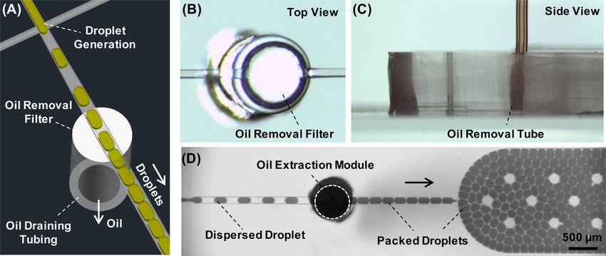
FIG. 1. Concept demonstration of the oil-removal and droplet-packing device. (a) Schematic showing oil removed through a membrane filter in a droplet-generation device.
(b) Top- and (c) side-view of the oil-removal module. (d) An experimental demonstration of oil removal and droplet packing in a microfluidic device. The flow rates of oil
and black dye are 2 and 1.5 μl/min; the outlet of the tube is left open (the oil is drained by gravity).
II. MATERIAL AND METHODS pump was used to drain the oil (see a representative experiment in
The key component to fabricate the oil-removal module is a Movie S1 of the supplementary material), enabling a quantitative
hydrophobic Fluoropore PTFE membrane filter with a 0.22-μm tuning of the droplet-packing density.
pore size (FGLP02500, EMD Millipore, Billerica, MA, USA).
Microbore PTFE tubings are used for device and fluidic connec- III. RESULT AND DISCUSSION
tions (SK-06417-11/21/31, Cole Parmer, Vernon Hills, IL, USA). A. Effect of flow rates on oil extraction efficiency
Other regular materials, in addition to all chemicals and instru-
ment, can be found in the supplementary material. The effect of the oil-withdrawal rate on oil-removal efficiency
was first tested at a fixed droplet-generation rate (2 and 1 μl/min for
oil and water infusion). The oil-withdrawal rate was then increased
A. Device fabrication
(indicated as D) from 0.0 to 2.1 μl/min in steps of 0.3 μl/min. When
A thick polydimethylsiloxane (PDMS) slab (3–5 mm) with D is low, the droplets with the remaining oil exit from the oil-
microfluidic channels (40 μm in depth) was first fabricated via a removal module into a narrower channel, resulting in irregular
soft photolithography method and then bonded to a glass slide spaces between unpacked droplets [Figs. 2(a) and 2(b)]. Droplets
spin-coated with PDMS. The access ports were punched by 18- packing increased as D increased [Fig. 2(c)] until it approached
and 20-gauge needles (Jensen Global, Inc., Santa Barbara, CA, the oil infusion rate (indicated as O), where a fully packed
USA), including the one for the oil draining tube. As illustrated in droplet population was generated and observed in the chamber
Figs. 1(a)–1(d), a 3 × 3 mm2 piece of a filter membrane was placed [Fig. 2(d)]. The interval length between droplets was measured
flat on top of the draining hole and pushed to the bottom of the before (I1) and after (I2) the oil removing process, and it was
channel by a blunt PTFE tube (1.5-cm long), forming a circular mem- found that I2 linearly decreases as the oil-withdrawal rate D
brane that separates the channel from the tube and allows oil to be fil- increases [I2 = −114.3D + 221.1 with r2 = 0.9858, Fig. 2(e), blue
tered through the 0.22-μm pores into the tube outlet while keeping line]. The oil-removal efficiency, defined as E% = (1 − I2/I1) × 100%,
aqueous droplets (typically 100 μm in diameter) remained flowing in was inversely proportional to I2 and increased with the oil-
the channel. The diameter of the filtering chamber was defined by the withdrawal rate [Fig. 2(e), black line]. Both experimental measure-
outer diameter of the inserted tube, which was 1.07 mm, and the ments of I2 (filled blue squares) and E% (filled black circles) match
depth was made to be the same as the channel height. their respective theoretical values (empty triangles) calculated based
The oil-removal device was initially tested by leaving the outlet on the ratios of the oil withdraw rate D and the infusion rate O,
of the draining tube open. Flipping the device over, the heavier oil which give: I2 = I1 × (1 − D/O) and E% = D/O × 100%. It should be
(ρ = 1.614 g/ml) could be efficiently removed by gravity under the noted that the oil-removal efficiency of 100% (when the neighboring
tested flow rate [Fig. 1(d)]. To further investigate the effect of the oil- droplets are closely packed) does not mean that the oil is removed
withdrawal rate on oil-removal efficiency, an additional syringe completely. A minimal amount of oil remains outside of the
Biomicrofluidics 15, 024108 (2021); doi: 10.1063/5.0047924 15, 024108-2
Published under license by AIP Publishing.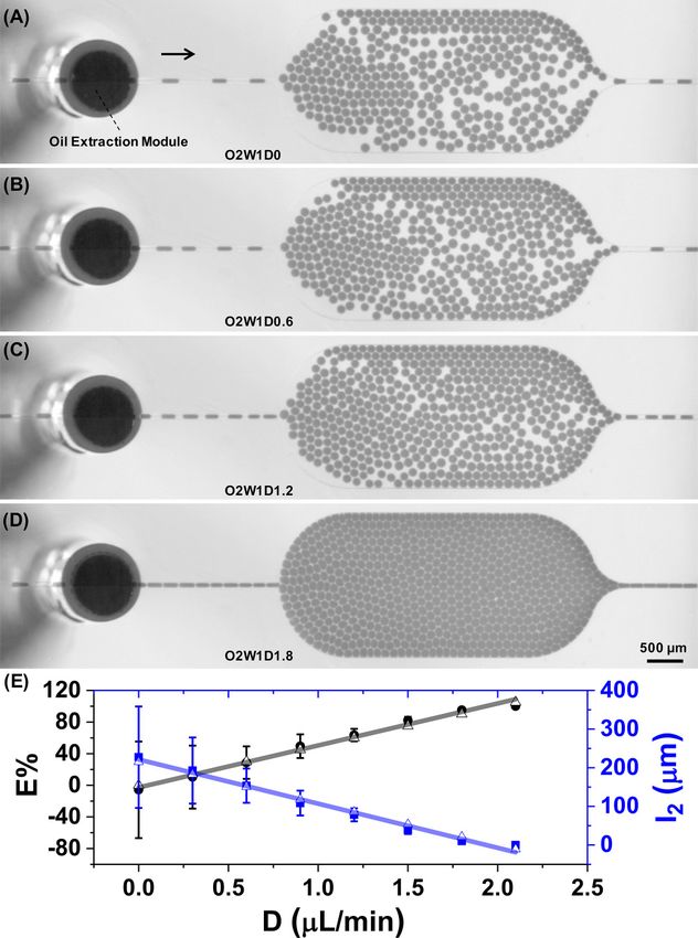
Biomicrofluidics                                                                                                   ARTICLE                scitation.org/journal/bmf

                                                                                              FIG. 3. (a) Droplets tagged with a black dye using a K-junction device. (b)
                                                                                              Stitched picture showing black droplets traveling in a connecting tubing within a
                                                                                              confined zone after oil removal. (c) Contrast adjusted image of (b) for grayscale
                                                                                              evaluation of the droplet distribution in the tubing. The flow rate of the droplets
                                                                                              in the tubing: 1.6 μl/min. The arrow indicates the flow direction. Scale bars:
                                                                                              500 μm.

                                                                                             removed from the droplet train, results in highly packed droplets
                                                                                             that can be controllably incubated, as described below.

                                                                                             B. Importance of removing oil and forming packed
                                                                                             droplets in time-controllable droplet-based assays
                                                                                                  Droplet incubation in tubing has been reported previously,6,14
      FIG. 2. The effect of the oil-withdrawal rate on oil-removal efficiency at a fixed     but it has not been shown to allow precise incubation on account of
      droplet-generation rate (O = 2.0 and W = 1.0). A series of images at (a) D = 0.0,      loosely packed droplets within the tubing, which can then have differ-
      (b) D = 0.6, (c) D = 1.2, and (d) D = 1.8. O, W, and D represent the flow rate of      ential transport rates within the tubing. To demonstrate improved
      oil infusion, water infusion, and oil withdrawal, unit: μl/min. (e) The plot of oil-   droplet incubation afforded by droplet packing, a K-junction device15
      removal efficiency E (black circles) and droplet space I2 (blue squares, averaged      was used to tag ∼1000 droplets with a black dye by applying an
      from ∼60 drops) vs oil withdrawing rate D. The hollow triangles represent theo-
                                                                                             electrical droplet injection potential for 10 s [Fig. 3(a)]. The sub-
      retical values.
                                                                                             sequent plug of packed droplets is then incubated within the
                                                                                             tubing [Fig. 3(b)]. Although there is still some droplet diffusion, a
                                                                                             large majority of the dyed droplets (>99%) are confined within a
    droplets to maintain droplet separation. Further increasing the oil-                     20-s zone [Fig. 3(c)]. This occurs because the droplets are tightly
    withdrawal rate causes droplets to deform, break up, and merge                           packed, which limits dispersion within the external incubation
    when they transition between channels in different dimensions.                           tubing (Movie S2 in the supplementary material), with the observed
          The water infusion rate was then altered to change the volume                      dispersion likely due to droplets rearrangement at the intersection of
    fraction of water to investigate the effect on the oil-removal effi-                     two channels having different dimensions or at curved features
    ciency under fixed oil infusion and withdrawal rates. When the                           within the channels.16 In contrast, droplets that have not been tightly
    volume fraction of aqueous and oil phases decreased from 1.0 to                          packed via controlled oil removal show a high degree of dispersion,
    0.25, there was no significant difference in the oil-removal efficiency,                 with large observed gaps of dyed droplets within the undyed back-
    but slightly less packed droplets were observed at lower volume frac-                    ground droplets (Movie S3 in the supplementary material). This
    tion (Fig. S1 in the supplementary material). The same trend was                         homogenous droplet incubation time is important for steps in which
    discovered upon increasing the flow rates (Fig. S2 in the supplementary                  precise timing of in-droplet chemistries needs to be maintained,
    material). It follows that lower packing efficiencies may be observed                    including application such as reagent injection,17 droplet fusion,
    under extreme flow conditions.                                                           or synchronization.18,19 The described oil extraction module is
          These findings indicate that the oil-removal efficiency is                         valuable for restoring tight droplet dispersion (Fig. S3 in the
    largely dictated by the oil-withdrawal rate. Near matching of the                        supplementary material), making this approach versatile for many
    oil-withdrawal and infusion rates, more than 95% of the oil can be                       different potential applications.

Biomicrofluidics 15, 024108 (2021); doi: 10.1063/5.0047924                                                                                                                15, 024108-3
Published under license by AIP Publishing.
Biomicrofluidics ARTICLE scitation.org/journal/bmf
C. Demonstration of a homogenous enzymatic assay β-D-galactopyranoside to fluorescent resorufin via a reaction with a
through packed droplets β-galactosidase enzyme. The devices were assembled on a confocal
To demonstrate the flexibility of altering incubation time with microscope with 561 nm excitation and a detection bandpass filter
packed droplets, we bridged a droplet-packing device [Fig. 4(a) (i)] with a 40 nm transmission window centered at 593 nm (additional
information can be found in the supplementary material). In this
to a detection device [Fig. 4(a) (iii)] with another piece of exter-
way, the fluorescent resorufin generated by the enzymatic conver-
nal plugged-in tubing. Two aqueous streams containing enzyme
sion of the substrate was detected in individual droplets after
and substrate solutions, respectively, were combined into drop- respacing them downstream of Device II [Fig. 4(a)]. Figure 4(b)
lets, with subsequent oil removal to form packed droplets (Movie shows four independent trace lines of droplet intensity after
S4 in the supplementary material). The enzyme and substrate- droplets were incubated for various times from 3 to 20 min (a full
containing droplets were then incubated for varying amounts of 10-s acquisition was recorded and presented in Fig. S4 of the
time flowing through tubing that bridged the packing and detec- supplementary material). Each trace represents the fluorescence
tion devices [Fig. 4(a) (ii)]. Reaction incubation time was varied intensity of droplets after incubation for the specified times. As
by using bridging tubing with different diameters and lengths expected, the average fluorescent intensity increases with increas-
(see Table S1 in the supplementary material) to achieve reactions ing reaction time owing to more complete substrate conversion
ranging from 3 to 20 min. [Fig. 4(c)]. Importantly, the width of the plugs of fluorescent
The enzymatic assay performed to show the homogeneity of droplets retains their temporal homogeneity even up to the
reactions within packed droplets even during long incubation times 20-min reaction time. This is due to the tightly packed droplets
was the conversion of the non-fluorescent substrate resorufin that travel through the incubation tubing that are not able to
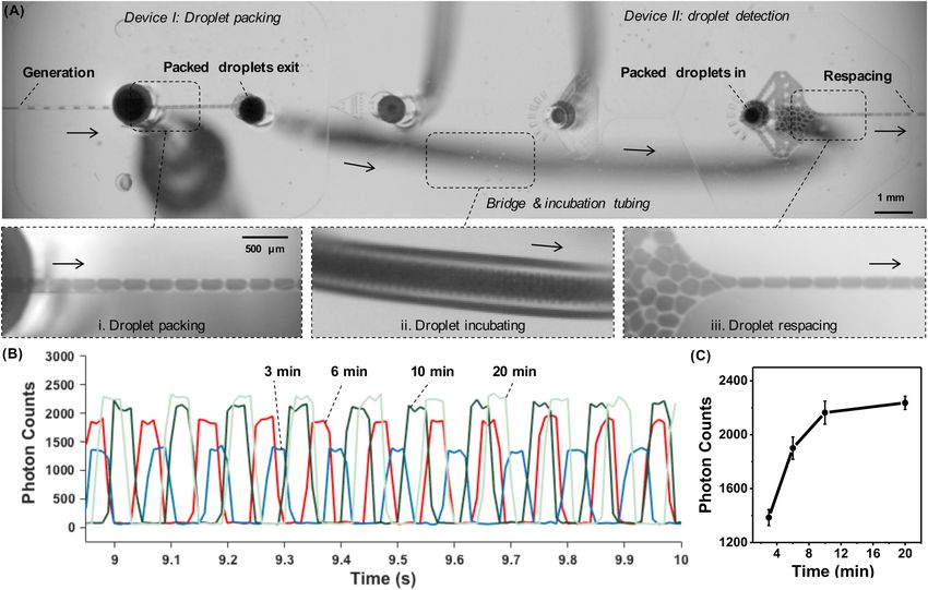
FIG. 4. The connection of two devices via a bridging tubing for a droplet-based enzymatic assay. (a) Pictures showing packed droplets (i) formed after oil removal, (ii)
incubated in a 5-cm long tubing (above the focus plane), and (iii) reinjected and respaced in a droplet detection device for the measurement of enzymatic activities.
Flow rate: O = 2.0, W = 1.0, and D = 1.8 μl/min. (b) Enzymatic activities measured in photon counts after a different incubation time: blue, 3 min; red, 6 min; dark green,
10 min; and light green, 20 min. Flow rate: O = 2.0, W1 (substrate) = 0.5, W2 (enzyme) = 0.5, and D = 1.8 μl/min. (c) Enzymatic activity (averaged from ∼100 droplets)
vs incubation time.
Biomicrofluidics 15, 024108 (2021); doi: 10.1063/5.0047924 15, 024108-4
Published under license by AIP Publishing.Biomicrofluidics ARTICLE scitation.org/journal/bmf
spread out during transit. In fact, the relative standard deviations NIGMS-R35GM119688), the National Science Foundation
of the height of all of these traces is less than 4.5%, implying that (Early Career Grant No. 1553031; MCB No. 1817909), and the
the droplets have kept their generation order in a packed zone Alfred P. Sloan Foundation. The authors also wish to thank the
while traveling in the incubation tubing. By comparing droplets Single Molecule Analysis in Real-Time (SMART) Center of the
spanning with and without oil removal shown in Fig. 3 and University of Michigan, seeded by NSF MRI-R2-ID Award No.
Movie S3 of the supplementary material, it is expected that a DBI-0959823 to Nils G. Walter, as well as J. Damon Hoff for training
nearly fivefold expansion of the droplets zone without oil being and use of Alba v5 confocal spectroscopy.
first removed. This expansion could induce a larger variation for
droplet traveling/incubation time, which, for a time-sensitive DATA AVAILABILITY
kinetic assay shown in Fig. 4(c), could, in theory, result in a wide
distribution of fluorescence intensity. In this way, we demonstrate The data that support the findings of this study are available
the value of oil removal and tight droplet packing as a way to within the article.
achieve highly homogenous droplet reaction times even during
long incubations needed for any common enzymatic reactions. REFERENCES
Although we only demonstrated incubation up to 20 min for this 1
D. K. Kang, M. Monsur Ali, K. Zhang, E. J. Pone, and W. Zhao, TrAC Trends
specific assay, further extension of incubation time can be
Anal. Chem. 58, 145–153 (2014).
achieved by stopping the flow after droplets are tightly packed in 2
H. N. Joensson and H. Andersson-Svahn, Angew. Chem. Int. Ed. 51,
a tubing until a desired period of incubation, ranging from 12176–12192 (2012).
minutes to a couple of months,20 is reached. 3
N. Shembekar, C. Chaipan, R. Utharala, and C. A. Merten, Lab Chip 16,
1314–1331 (2016).
IV. CONCLUSIONS 4
Y. Ding, J. Choo, and A. J. deMello, Microfluid. Nanofluid. 21, 58 (2017).
5
M. Sun and Q. Fang, Lab Chip 10, 2864–2868 (2010).
A simple oil-removal module is described that uses plugged-in 6
J. J. Agresti, E. Antipov, A. R. Abate, K. Ahn, A. C. Rowat, J. C. Baret,
tubing and a PTFE membrane filter that allows for tight and con- M. Marquez, A. M. Klibanov, A. D. Griffiths, and D. A. Weitz, Proc. Natl. Acad.
trollable packing of aqueous droplets. These droplets can then be Sci. U.S.A. 107, 4004–4009 (2010).
transported to other devices via external tubing, which can allow for 7
H. Song and R. F. Ismagilov, J. Am. Chem. Soc. 125, 14613–14619 (2003).
a lengthy droplet incubation period that would be difficult to 8
L. Frenz, K. Blank, E. Brouzes, and A. D. Griffiths, Lab Chip 9, 1344–1348
achieve within a microfluidic device because of the size required (2009).
9
and subsequent back-pressure that would accompany such on-chip E. Brouzes, M. Medkova, N. Savenelli, D. Marran, M. Twardowski, J. B. Hutchison,
incubation. Controllable droplet packing is demonstrated by varying J. M. Rothberg, D. R. Link, N. Perrimon, and M. L. Samuels, Proc. Natl. Acad. Sci.
U.S.A. 106, 14195–14200 (2009).
the rate of oil removal in a way that is efficient and robust across 10
B. E. Debs, R. Utharala, I. V. Balyasnikova, A. D. Griffiths, and C. A. Merten,
different droplet-generation parameters. This simple module will Proc. Natl. Acad. Sci. U.S.A. 109, 11570–11575 (2012).
find utility in facilitating multistep assays that require transferring 11
J. R. Haliburton, S. C. Kim, I. C. Clark, R. A. Sperling, D. A. Weitz, and
droplets between devices or for allowing extended, homogenous A. R. Abate, Biomicrofluidics 11, 034111 (2017).
droplet incubation by maintaining tight droplet packing. This capa- 12
S. M. Bjork, S. L. Sjostrom, H. Andersson-Svahn, and H. N. Joensson,
bility was demonstrated through variable time enzymatic assays that Biomicrofluidics 9, 044128 (2015).
showed maintenance of droplet plug integrity even during long 13
J. Dai, H. Soo Kim, A. R. Guzman, W. B. Shim, and A. Han, RSC Adv. 6,
reaction times. This extended, homogenous incubation could also 20516–20519 (2016).
facilitate studies of droplet-to-droplet exchange in which the dis-
14
P. A. Romero, T. M. Tran, and A. R. Abate, Proc. Natl. Acad. Sci. U.S.A. 112,
tance between droplets plays an important role that can be a source 7159–7164 (2015).
15
S. R. Doonan and R. C. Bailey, Anal. Chem. 89, 4091–4099 (2017).
of noise.21,22 One such application currently under investigation in 16
E. Surenjav, S. Herminghaus, C. Priest, and R. Seemann, Appl. Phys. Lett. 95,
our laboratory involves incubation and communication between 154104 (2009).
droplet-based artificial cells.23–25 17
A. R. Abate, T. Hung, P. Mary, J. J. Agresti, and D. A. Weitz, Proc. Natl. Acad.
Sci. U.S.A. 107, 19163–19166 (2010).
SUPPLEMENTARY MATERIAL 18
L. Mazutis, J. C. Baret, and A. D. Griffiths, Lab Chip 9, 2665–2672 (2009).
19
M. Lee, J. W. Collins, D. M. Aubrecht, R. A. Sperling, L. Solomon, J. W. Ha,
See the supplementary material for Chemicals, Materials, and
G. R. Yi, D. A. Weitz, and V. N. Manoharan, Lab Chip 14, 509–513 (2013).
Instrument; incubation time with different tubings (Table S1); 20
L. Li, D. Mustafi, Q. Fu, V. Tereshko, D. L. Chen, J. D. Tice, and R. F. Ismagilov,
effects of volume fraction (Fig. S1) and droplet-generation rate Proc. Natl. Acad. Sci. U.S.A. 103, 19243–19248 (2006).
(Fig. S2) on oil-removal efficiency; periodicity restoring from rein- 21
M. Weitz, A. Mückl, K. Kapsner, R. Berg, A. Meyer, and F. C. Simmel, J. Am.
jected droplets (Fig. S3) and full traces of droplet detection of the Chem. Soc. 136, 72–75 (2014).
22
enzyme assay (Fig. S4); and video recordings of droplet packing P. Gruner, B. Riechers, B. Semin, J. Lim, A. Johnston, K. Short, and
with (Movies S1, S2, and S4) and without oil removal (Movie S3). J.-C. Baret, Nat. Commun. 7, 10392 (2016).
23
Y. Guan, Z. Li, S. Wang, P. M. Barnes, X. Liu, H. Xu, M. Jin, A. P. Liu, and
ACKNOWLEDGMENTS Q. Yang, eLife 7, e33549 (2018).
24
Y. Guan, S. Wang, M. Jin, H. Xu, and Q. Yang, J. Vis. Exp. 139, e58240 (2018).
We gratefully acknowledge financial support from the 25
M. Sun, Z. Li, S. Wang, G. Maryu, and Q. Yang, Anal. Chem. 91, 9813–9818
National Institutes of Health (Grant Nos. CA191186 and (2019).
Biomicrofluidics 15, 024108 (2021); doi: 10.1063/5.0047924 15, 024108-5
Published under license by AIP Publishing.You can also read