MYFLOW DRIVE INSTALLATION/OPERATING MANUAL - KSB WEB-SHOP
←
→
Page content transcription
If your browser does not render page correctly, please read the page content below
MyFlow Drive

Installation/Operating Manual
Legal information/Copyright
Installation/Operating Manual MyFlow Drive

Original operating manual

All rights reserved. The contents provided herein must neither be distributed, copied, reproduced,
edited or processed for any other purpose, nor otherwise transmitted, published or made available to a
third party without the manufacturer's express written consent.
Subject to technical modification without prior notice.

© KSB SE & Co. KGaA, Frankenthal 20/01/2021
Contents

                                        Contents
    Glossary .................................................................................................................................................. 6
1   General.................................................................................................................................................... 7
    1.1    Principles ...........................................................................................................................................................   7
    1.2    Target group.....................................................................................................................................................        7
    1.3    Other applicable documents............................................................................................................................                   7
    1.4    Symbols .............................................................................................................................................................    7
    1.5    Key to safety symbols/markings.......................................................................................................................                    8

2   Safety ...................................................................................................................................................... 9
    2.1    General.............................................................................................................................................................. 9
    2.2    Intended use ..................................................................................................................................................... 9
    2.3    Personnel qualification and training............................................................................................................... 9
    2.4    Consequences and risks caused by non-compliance with this operating manual........................................ 9
    2.5    Safety awareness ............................................................................................................................................ 10
    2.6    Safety information for the user/operator ..................................................................................................... 10
    2.7    Safety information for maintenance, inspection and installation .............................................................. 10
    2.8    Unauthorised modes of operation ................................................................................................................ 10
    2.9    Software changes ........................................................................................................................................... 10
    2.10   Electromagnetic compatibility (EMC)............................................................................................................ 10
           2.10.1 Interference emission requirements ................................................................................................. 10
           2.10.2 Line harmonics requirements............................................................................................................ 11
           2.10.3 Interference immunity requirements ............................................................................................... 12

3   Transport/Storage/Disposal ................................................................................................................ 13
    3.1    Checking the condition upon delivery ..........................................................................................................                        13
    3.2    Transport.........................................................................................................................................................     13
    3.3    Storage ............................................................................................................................................................   14
    3.4    Disposal/recycling ...........................................................................................................................................         14

4   Description............................................................................................................................................ 15
    4.1    General description ........................................................................................................................................           15
    4.2    Product information as per Regulation No. 1907/2006 (REACH).................................................................                                           15
    4.3    Designation.....................................................................................................................................................       15
    4.4    Name plate......................................................................................................................................................       17
    4.5    Power range and sizes....................................................................................................................................              17
    4.6    Technical data.................................................................................................................................................        18
    4.7    Dimensions and weights ................................................................................................................................                20
    4.8    Mounting type................................................................................................................................................          21

5   Installation at site ................................................................................................................................ 22
    5.1    Safety regulations........................................................................................................................................... 22
    5.2    Checks to be carried out prior to installation............................................................................................... 22
    5.3    Mounting the frequency inverter.................................................................................................................. 22
    5.4    Electrical Connection...................................................................................................................................... 22
           5.4.1 Safety regulations .............................................................................................................................. 22
           5.4.2 Information for planning the system ............................................................................................... 24
           5.4.2.1       Connection cables ..................................................................................................................... 24
           5.4.2.2       Electrical protection equipment .............................................................................................. 25
           5.4.2.3       Information on electromagnetic compatibility....................................................................... 26
           5.4.2.4       Earth connection....................................................................................................................... 26
           5.4.2.5       Line chokes ................................................................................................................................ 26
           5.4.3 Electrical connection.......................................................................................................................... 27
           5.4.3.1       Removing the housing cover (models up to 11 kW)............................................................... 27
           5.4.3.2       Removing the housing cover (models from 15 kW to 45 kW) ............................................... 28
           5.4.3.3       Overview of terminal strips ...................................................................................................... 30
           5.4.3.4       Connection to mains power supply and motor ...................................................................... 31

                                        MyFlow Drive                                                                                                                    3 of 84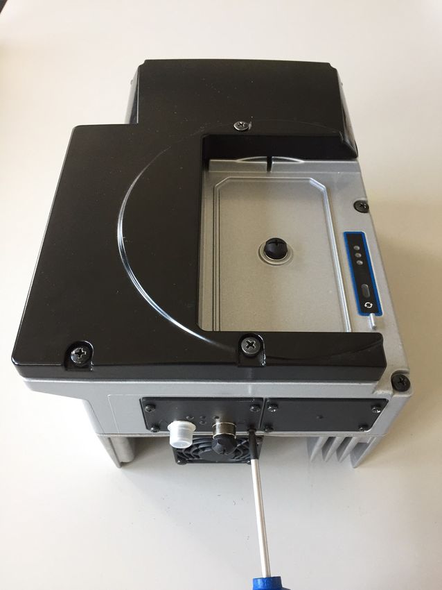
Contents
5.4.3.5 Establishing an earth connection............................................................................................. 35
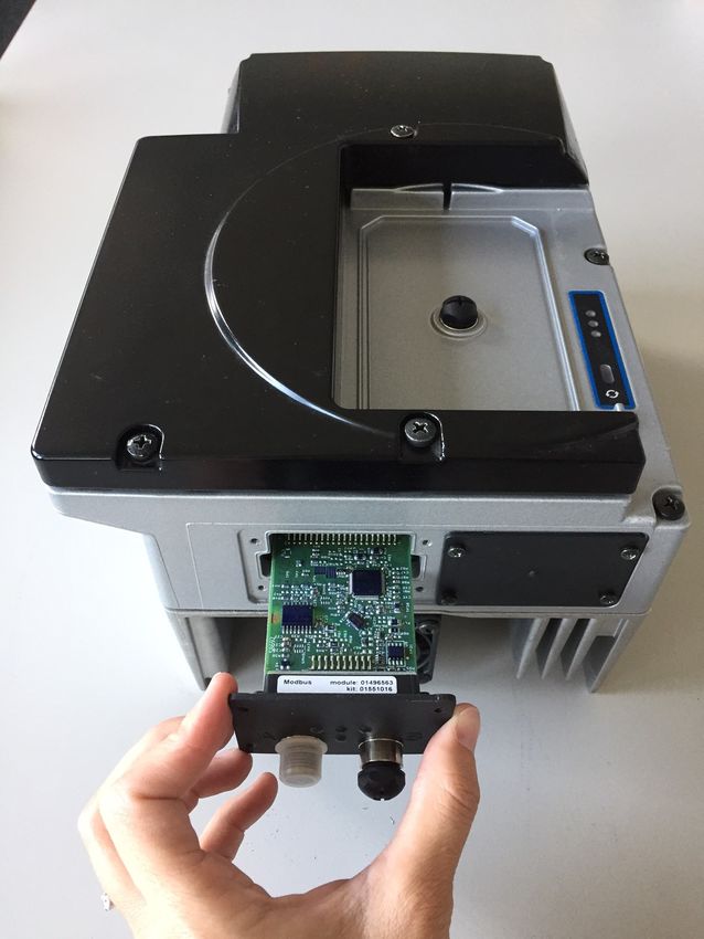
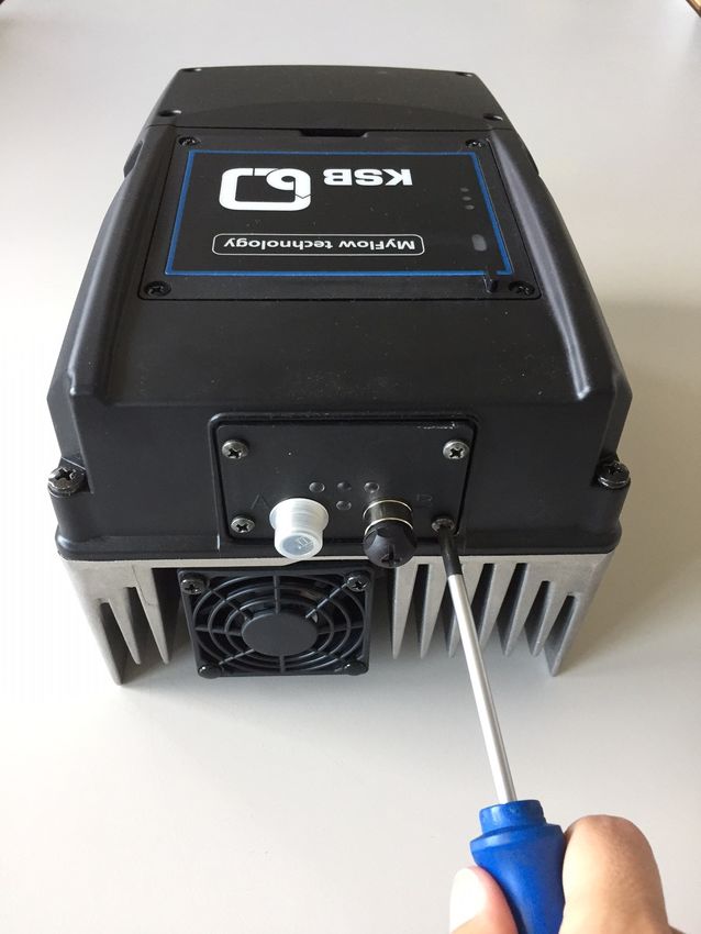
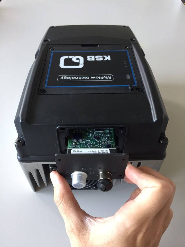
5.4.3.6 Installing and connecting the field bus module ..................................................................... 35
5.4.3.7 Connecting the field bus module ............................................................................................ 37
5.4.3.8 Connecting the control cable................................................................................................... 37
6 Operation.............................................................................................................................................. 41
6.1 Service interface and LED traffic light function ........................................................................................... 41
6.1.1 Settings ............................................................................................................................................... 42
6.1.1.1 Menu: Operation ...................................................................................................................... 42
6.1.1.2 Menu: Diagnosis........................................................................................................................ 43
6.1.1.3 Menu: Settings .......................................................................................................................... 44
6.1.1.4 Menu: Information ................................................................................................................... 44
7 Commissioning/Start-up/Shutdown................................................................................................... 45
7.1 Control point concept .................................................................................................................................... 45
7.2 Setting motor parameters.............................................................................................................................. 45
7.3 Motor control method ................................................................................................................................... 46
7.4 Automatic motor adaptation (AMA) of the frequency inverter ................................................................. 46
7.5 Entering the individual fixed speed .............................................................................................................. 48
7.6 Pump operation.............................................................................................................................................. 49
7.6.1 Operation at individual fixed speed ................................................................................................. 49
7.6.2 Changing the individual fixed speed via the KSB FlowManager app ............................................ 49
7.7 Application functions ..................................................................................................................................... 49
7.7.1 Protective functions ........................................................................................................................... 49
7.7.1.1 Activating/deactivating thermal motor protection ................................................................ 49
7.7.1.2 Electrical motor protection by overvoltage/undervoltage monitoring ................................. 50
7.7.1.3 Stop due to overcurrent ........................................................................................................... 50
7.7.1.4 Dynamic overload protection by speed limitation ................................................................. 50
7.7.1.5 Tripping at phase failure and short circuit.............................................................................. 51
7.7.1.6 Suppressing a frequency range................................................................................................ 51
7.7.1.7 Dry running protection and protection against hydraulic blockage ..................................... 52
7.7.1.8 Individual monitoring functions .............................................................................................. 53
7.7.2 Ramps ................................................................................................................................................. 53
7.7.3 Motor standstill heater...................................................................................................................... 54
7.8 Device functions ............................................................................................................................................. 55
7.8.1 Factory settings and user settings..................................................................................................... 55
7.8.2 Date and time .................................................................................................................................... 55
7.9 Digital input / relay output ............................................................................................................................ 55
7.9.1 Digital inputs...................................................................................................................................... 55
7.9.2 Relay output....................................................................................................................................... 56
7.9.3 Parameterising the field bus module ............................................................................................... 57
8 Servicing/Maintenance ........................................................................................................................ 58
8.1 Safety regulations........................................................................................................................................... 58
8.2 Servicing/Inspection........................................................................................................................................ 58
8.2.1 Supervision of operation ................................................................................................................... 58
8.3 Dismantling..................................................................................................................................................... 58
8.3.1 Preparing frequency inverter for dismantling ................................................................................. 58
9 Parameter List....................................................................................................................................... 59
10 Trouble-shooting.................................................................................................................................. 69
10.1 Trouble-shooting ............................................................................................................................................ 70
10.2 Alerts ............................................................................................................................................................... 71
10.3 Warnings ......................................................................................................................................................... 73
10.4 Information messages .................................................................................................................................... 75
11 Purchase Order Specifications............................................................................................................. 76
11.1 Ordering spare parts ...................................................................................................................................... 76
11.2 Accessories ...................................................................................................................................................... 77
11.2.1 Service software ................................................................................................................................. 77
4 of 84 MyFlow Drive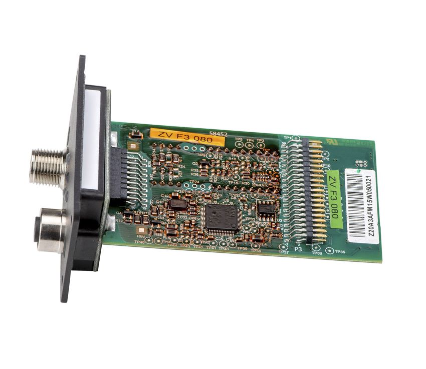
Contents

            11.2.2 Blind cover.......................................................................................................................................... 77
            11.2.3 Optional components ........................................................................................................................ 77
            11.2.4 Control cabinet mounting................................................................................................................. 78

12   Commissioning Report......................................................................................................................... 79
13   EU Declaration of Conformity ............................................................................................................. 80
     Index ..................................................................................................................................................... 81

                                       MyFlow Drive                                                                                                             5 of 84
Glossary

                                Glossary

Braking resistor
      Takes up the braking power produced during
      generator operation.

Hydraulic blockage
      Undesirable operating situation in which the
      pump cannot supply fluid due to a closed inlet or
      outlet.

IE1
      Efficiency class to IEC 60034-30: 1 = Standard
      Efficiency (IE = International Efficiency)

IE2
      Efficiency class to IEC 60034-30: 2 = High Efficiency
      (IE = International Efficiency)

IE3
      Efficiency class to IEC 60034-30: 3 = Premium
      Efficiency (IE = International Efficiency)

IE4
      Efficiency class to IEC TS 60034-30-2:2016 = Super
      Premium Efficiency (IE = International Efficiency)

IE5
      Efficiency class to IEC TS 60034-30-2:2016 = Ultra
      Premium Efficiency (IE = International Efficiency)

Pump
      Machine without drive, additional components or
      accessories

Pump set
      Complete pump set consisting of pump, drive,
      additional components and accessories

RCD
      Abbreviation for "residual current device"
                                                              4074.83/05-EN

6 of 84                         MyFlow Drive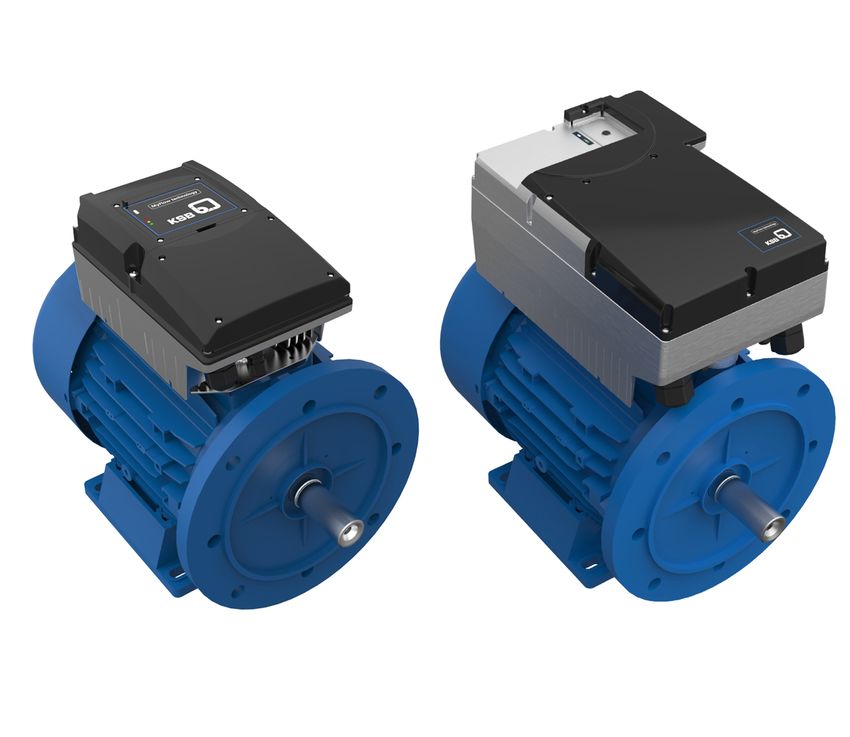
1 General

                               1 General

                               1.1 Principles
                               This operating manual is valid for the type series and variants indicated on the front
                               cover.
                               The operating manual describes the proper and safe use of this equipment in all
                               phases of operation.
                               The name plate indicates the type series, the main operating data and the serial
                               number. The serial number uniquely describes the product and is used as
                               identification in all further business processes.
                               In the event of damage, immediately contact your nearest KSB service facility to
                               maintain the right to claim under warranty.

                               1.2 Target group
                               This operating manual is aimed at the target group of trained and qualified specialist
                               technical personnel.

                               1.3 Other applicable documents
                               Table 1: Overview of other applicable documents
                               Document                            Contents
                               Operating manual                    Description of the proper and safe use of the
                                                                   pump in all phases of operation
                               Wiring diagram                      Description of the electrical connections
                               Supplementary operating             Description of the proper and safe use of
                               manual1)                            supplementary product components
                               For accessories and/or integrated machinery components, observe the relevant
                               manufacturer's product literature.

                               1.4 Symbols
                               Table 2: Symbols used in this manual
                               Symbol           Description
                                      ✓         Conditions which need to be fulfilled before proceeding with the
                                                step-by-step instructions
                                        ⊳       Safety instructions
                                      ⇨         Result of an action
                                      ⇨         Cross-references
                                      1.        Step-by-step instructions
                                      2.
                                                Note
                                                Recommendations and important information on how to handle
                                                the product
4074.83/05-EN

                1   Optional

                               MyFlow Drive                                                                    7 of 84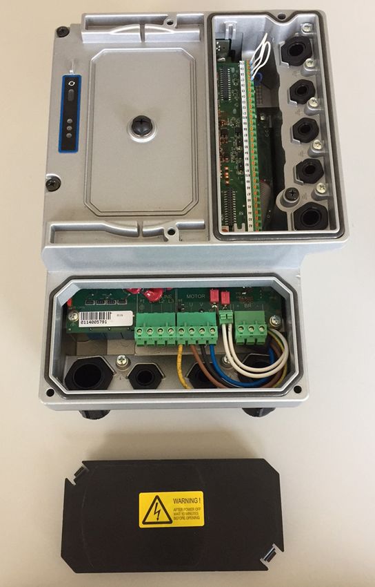
1 General

          1.5 Key to safety symbols/markings
          Table 3: Definition of safety symbols/markings
          Symbol           Description
            !    DANGER    DANGER
                           This signal word indicates a high-risk hazard which, if not avoided,
                           will result in death or serious injury.
            !   WARNING    WARNING
                           This signal word indicates a medium-risk hazard which, if not
                           avoided, could result in death or serious injury.
                CAUTION    CAUTION
                           This signal word indicates a hazard which, if not avoided, could
                           result in damage to the machine and its functions.
                           General hazard
                           In conjunction with one of the signal words this symbol indicates a
                           hazard which will or could result in death or serious injury.

                           Electrical hazard
                           In conjunction with one of the signal words this symbol indicates a
                           hazard involving electrical voltage and identifies information about
                           protection against electrical voltage.
                           Machine damage
                           In conjunction with the signal word CAUTION this symbol indicates
                           a hazard for the machine and its functions.

                                                                                                  4074.83/05-EN

8 of 84   MyFlow Drive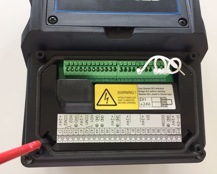
2 Safety

                             2 Safety
                             All the information contained in this section refers to hazardous situations.
                !   DANGER
                             In addition to the present general safety information the action-related safety
                             information given in the other sections must be observed.

                             2.1 General
                              ▪ This operating manual contains general installation, operating and maintenance
                                instructions that must be observed to ensure safe operation of the system and
                                prevent personal injury and damage to property.
                              ▪ Comply with all the safety instructions given in the individual sections of this
                                operating manual.
                              ▪ The operating manual must be read and understood by the responsible specialist
                                personnel/operators prior to installation and commissioning.
                              ▪ The contents of this operating manual must be available to the specialist
                                personnel at the site at all times.
                              ▪ Information and markings attached directly to the product must always be
                                complied with and kept in a perfectly legible condition at all times. This applies
                                to, for example:
                                  – Markings for connections
                                  – Name plate
                              ▪ The operator is responsible for ensuring compliance with all local regulations not
                                taken into account.

                             2.2 Intended use
                              ▪ This product must only be operated within the limit values stated in the technical
                                product literature for the mains voltage, mains frequency, ambient temperature,
                                motor rating, fluid handled, flow rate, speed, density, pressure, temperature and
                                in compliance with any other instructions provided in the operating manual or
                                other applicable documents.
                              ▪ The product must not be used in potentially explosive atmospheres.

                             2.3 Personnel qualification and training
                              ▪ All personnel involved must be fully qualified to install, operate, maintain and
                                inspect the product this manual refers to.
                              ▪ The responsibilities, competence and supervision of all personnel involved in
                                transport, installation, operation, maintenance and inspection must be clearly
                                defined by the operator.
                              ▪ Deficits in knowledge must be rectified by means of training and instruction
                                provided by sufficiently trained specialist personnel. If required, the operator can
                                commission the manufacturer/supplier to train the personnel.
                              ▪ Training on the product must always be supervised by specialist technical
                                personnel.

                             2.4 Consequences and risks caused by non-compliance with this operating
                             manual
4074.83/05-EN

                              ▪ Non-compliance with this operating manual will lead to forfeiture of warranty
                                cover and of any and all rights to claims for damages.
                              ▪ Non-compliance can, for example, have the following consequences:
                                  – Hazards to persons due to electrical, thermal, mechanical and chemical
                                    effects and explosions
                                  – Failure of important product functions
                                  – Failure of prescribed maintenance and servicing practices

                             MyFlow Drive                                                                      9 of 84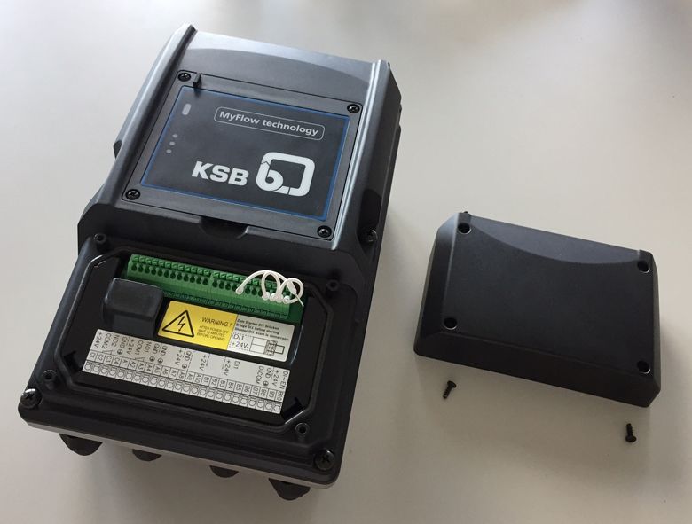
2 Safety

           2.5 Safety awareness
           In addition to the safety information contained in this operating manual and the
           intended use, the following safety regulations shall be complied with:
            ▪ Accident prevention, health regulations and safety regulations
            ▪ Explosion protection regulations
            ▪ Safety regulations for handling hazardous substances
            ▪ Applicable standards, directives and legislation (e.g. EN 50110-1)

           2.6 Safety information for the user/operator
            ▪ Fit protective equipment (e.g. contact guards) supplied by the operator for hot,
              cold or moving parts, and check that the equipment functions properly.
            ▪ Do not remove any protective equipment (e.g. contact guards) during operation.
            ▪ Provide the personnel with protective equipment and make sure it is used.
            ▪ Eliminate all electrical hazards. (In this respect refer to the applicable national
              safety regulations and/or regulations issued by the local energy supply
              companies.)

           2.7 Safety information for maintenance, inspection and installation
            ▪ Modifications or alterations of the pump (set) are only permitted with the
              manufacturer's prior consent.
            ▪ Use only original spare parts or parts/components authorised by the
              manufacturer. The use of other parts/components can invalidate any liability of
              the manufacturer for resulting damage.
            ▪ The operator ensures that maintenance, inspection and installation are
              performed by authorised, qualified specialist personnel who are thoroughly
              familiar with the manual.
            ▪ Any work on the product shall only be performed when it has been disconnected
              from the power supply (de-energised).
            ▪ Carry out work on the product during standstill only.
            ▪ As soon as the work has been completed, re-install and re-activate any safety-
              relevant devices and protective devices. Before returning the product to service,
              observe all instructions on commissioning.

           2.8 Unauthorised modes of operation
           Never operate the product outside the limits stated in the data sheet and in this
           manual.
           The warranty relating to the operating reliability and safety of the product supplied
           is only valid if the product is used in accordance with its intended use.

           2.9 Software changes
           The software has been specially created for this product and thoroughly tested.
           Making changes or additions to the software or parts of the software is prohibited.
           This does not, however, apply to software updates supplied by KSB.

           2.10 Electromagnetic compatibility (EMC)
                                                                                                    4074.83/05-EN

           2.10.1 Interference emission requirements
           The EN 61800-3 EMC product standard is relevant for electric variable speed drives/
           control systems. It specifies all pertinent requirements and refers to the relevant
           generic standards for complying with the EMC Directive.
           Frequency inverters are commonly used by operators as a part of a system, plant or
           machine assembly. It should be noted that the operator bears all responsibility for
           the final EMC properties of the equipment, plant or installation.

10 of 84   MyFlow Drive
2 Safety
A prerequisite or requirement for complying with the relevant standards or the limit
values and inspection/test levels referenced by them is that all information and
descriptions regarding EMC-compliant installation be observed and followed.
(ð Section 5.4, Page 22)
In accordance with the EMC product standard, the EMC requirements to be met
depend on the purpose or intended use of the frequency inverter. Four categories
are defined in the EMC product standard:
Table 4: Categories of intended use
Category Definition Limits to EN 55011
C1 Frequency inverters with a supply voltage under 1000 V installed in the Class B
first environment (residential and office areas).
C2 Frequency inverters with a supply voltage under 1000 V installed in the Class A, Group 1
first environment (residential and office areas) that are neither ready to
be plugged in/connected nor are mobile and must be installed and
commissioned by specialist personnel.
C3 Frequency inverters with a supply voltage under 1000 V installed in the Class A, Group 2
second environment (industrial environments).
C4 Frequency inverters with a supply voltage over 1000 V and a nominal No borderline/
current over 400 A installed in the second environment (industrial boundary2)
environments) or that are envisaged for use in complex systems.
The following limit values and inspection/test levels must be complied with if the
generic standard on interference emissions applies:
Table 5: Classification of installation environment
Environment Generic standard Limits to EN 55011
First environment (residential and office areas) EN/IEC 61000-6-3 Class B
for private, business and commercial
environments
Second environment (industrial environments) EN/IEC 61000-6-4 Class A, Group 1
for industrial environments
The frequency inverter meets the following requirements:
Table 6: EMC properties of the frequency inverter
Power Category to EN 61800-3 Limits to EN 55011
[kW]
≤ 11 C1 Class B
15 to 45 C2 Class A, Group 1
The EN 61800-3 standard requires that the following warning be provided for drive
systems that do not comply with category C1 specifications:
This product can produce high-frequency interference emissions that may necessitate
targeted interference suppression measures in a residential or office environment.
2.10.2 Line harmonics requirements
The product is a device for professional applications as defined by EN 61000-3-2. The
following generic standards apply when establishing a connection to the public
power grid:
▪ EN 61000-3-2
4074.83/05-EN
for symmetric, three-phase devices (professional devices with a total power of up
to 1 kW)
▪ EN 61000-3-12
for devices with a phase current of between 16 A and 75 A and professional
devices from 1 kW up to a phase current of 16 A.
2 An EMC plan must be devised.
MyFlow Drive 11 of 842 Safety
2.10.3 Interference immunity requirements
In general, the interference immunity requirements for a frequency inverter hinge on
the specific environment in which the inverter is installed.
The requirements for industrial environments are therefore higher than those for
residential and office environments.
The frequency inverter is designed such that the immunity requirements for
industrial environments and, thus, the lower-level requirements for residential and
office environments, are met and fulfilled.
The following relevant generic standards are used for the interference immunity test:
▪ EN 61000-4-2: Electromagnetic compatibility (EMC)
– Part 4-2: Testing and measurement techniques – Electrostatic discharge
immunity test
▪ EN 61000-4-3: Electromagnetic compatibility (EMC)
– Part 4-3: Testing and measurement techniques – Radiated, radio-frequency,
electromagnetic field immunity test
▪ EN 61000-4-4: Electromagnetic compatibility (EMC)
– Part 4-4: Testing and measurement techniques – Electrical fast transient/burst
immunity test
▪ EN 61000-4-5: Electromagnetic compatibility (EMC)
– Part 4-5: Testing and measurement techniques – Surge immunity test
▪ EN 61000-4-6: Electromagnetic compatibility (EMC)
– Part 4-6: Testing and measurement techniques – Immunity to conducted
disturbances, induced by radio-frequency fields
4074.83/05-EN
12 of 84 MyFlow Drive3 Transport/Storage/Disposal
3 Transport/Storage/Disposal
3.1 Checking the condition upon delivery
1. On transfer of goods, check each packaging unit for damage.
2. In the event of in-transit damage, assess the exact damage, document it and
notify KSB or the supplying dealer and the insurer about the damage in writing
immediately.
3.2 Transport
DANGER
The pump (set) could slip out of the suspension arrangement
Danger to life from falling parts!
▷ Always transport the pump (set) in the specified position.
▷ Never attach the suspension arrangement to the free shaft end or the motor
eyebolt.
▷ Observe the information about weights, centre of gravity and fastening points.
▷ Observe the applicable local accident prevention regulations.
▷ Use suitable, permitted lifting accessories, e.g. self-tightening lifting tongs.
To transport the pump/pump set suspend it from the lifting tackle as shown.
Fig. 1: Transporting a close-coupled pump set
Fig. 2: Transporting a horizontal pump set
4074.83/05-EN
MyFlow Drive 13 of 843 Transport/Storage/Disposal
Fig. 3: Transporting the motor with frequency inverter
3.3 Storage
If the ambient conditions for storage are met, the frequency inverter will give
reliable service even after a prolonged period of storage.
CAUTION
Damage during storage due to humidity, dirt or vermin
Corrosion/contamination of the frequency inverter!
▷ For outdoor storage, cover the (packed or unpacked) frequency inverter and
accessories with waterproof material.
Table 7: Ambient conditions for storage
Ambient condition Value
Relative humidity 85 % max. (non-condensing)
Ambient temperature -10 °C to +70 °C
▪ Store the frequency inverter under dry and vibration-free conditions, if possible
in its original packaging.
▪ Store the frequency inverter in a dry room where the level of atmospheric
humidity is as constant as possible.
▪ Prevent excessive fluctuations in atmospheric humidity (see table on ambient
conditions for storage).
3.4 Disposal/recycling
Electrical or electronic equipment marked with the adjacent symbol must not be
disposed of in household waste at the end of its service life.
Contact your local waste disposal partner for returns.
If the used electrical or electronic equipment contains personal data, the operator is
responsible for deleting it before the equipment is returned.
The product is classified as special waste due to several installed components:
1. Dismantle the product.
2. Separate materials
e.g.:
- Aluminium
4074.83/05-EN
- Plastic cover (recyclable plastic)
- Line chokes with copper windings
- Copper lines for internal wiring
3. Dispose of materials in accordance with local regulations or in another
controlled manner.
PCBs, power electronics, capacitors and electronic components are all special
waste.
14 of 84 MyFlow Drive4 Description
4 Description
4.1 General description
Drive solution with IE5 synchronous reluctance motor and motor-mounted minimum
frequency inverter for applications with a constant flow rate
4.2 Product information as per Regulation No. 1907/2006 (REACH)
For information as per chemicals Regulation (EC) No 1907/2006 (REACH), see https://
www.ksb.com/ksb-de/konzern/Unternehmerische_Verantwortung/reach/
4.3 Designation
Table 8: Designation example
Position
1 2 3 4 5 6 7 8 9 10 11 12 13 14 15 16 17 18 19 20 21 22 23 24 25 26 27 28 29 30
P D R V 2 I - 0 1 1 K 0 0 M _ K S U P B E 5 P 2 _ O O O O O
Table 9: Designation key
PumpDrive 2 Eco
Position Code Description
MyFlow Drive
PumpDrive 2
1-5 Product generation
PDRV2 PumpDrive 2 ✘ ✘ ✘
6 Design
E PumpDrive 2 Eco - ✘ -
I MyFlow Drive ✘ - -
- PumpDrive 2 - - ✘
7 Product certifications
- CE ✘3) ✘ -
R UR and CE ✘4) - ✘
L UL and CE - - ✘5)
8-13 Power
A 000K37 = 0,37 kW - ✘ ✘
000K55 = 0,55 kW ✘ ✘ ✘
000K75 = 0,75 kW ✘ ✘ ✘
001K10 = 1,1 kW ✘ ✘ ✘
001K50 = 1,5 kW ✘ ✘ ✘
B 002K20 = 2,2 kW ✘ ✘ ✘
003K00 = 3 kW ✘ ✘ ✘
004K00 = 4 kW ✘ ✘ ✘
C 005K50 = 5,5 kW ✘ ✘ ✘
007K50 = 7,5 kW ✘ ✘ ✘
4074.83/05-EN
011K00 = 11 kW ✘ ✘ ✘
D 015K00 = 15 kW ✘ - ✘
018K50 = 18,5 kW ✘ - ✘
022K00 = 22 kW ✘ - ✘
3 Available only for sizes ≤ 11 kW
4 Available only for sizes 15 kW to 45 kW
5 Available on request only
MyFlow Drive 15 of 844 Description
PumpDrive 2 Eco
Position Code Description
MyFlow Drive
PumpDrive 2
8-13 D 030K00 = 30 kW ✘ - ✘
E 037K00 = 37 kW ✘ - ✘
045K00 = 45 kW ✘ - ✘
055K00 = 55 kW - - ✘
14 Mounting option
M Motor mounting ✘ ✘ ✘
W Wall mounting - ✘ ✘
C Cabinet mounting - ✘ ✘
16 Motor manufacturer
K KSB ✘ ✘ ✘
S Siemens - ✘ ✘
C Cantoni - ✘ ✘
W Wonder - ✘ ✘
17-20 Motor type
1LE1 Siemens 1LE1/ KSB 1PC3 - ✘ ✘
1LA7 Siemens 1LA7/ KSB 1LA7 - ✘ ✘
1LA9 Siemens 1LA9/ KSB 1LA9 - ✘ ✘
1LG6 Siemens 1LG6/ KSB 1LG6 - ✘ ✘
SUPB KSB SuPremE B ✘ ✘ ✘
DMC KSB(DM) Cantoni - ✘ ✘
DMW KSB(DM) Wonder - ✘ ✘
21-22 Efficiency class
E1 IE1 - ✘ ✘
E2 IE2 - ✘ ✘
E3 IE3 - ✘ ✘
E4 IE4 ✘ ✘ ✘
E5 IE5 ✘ ✘ ✘
23-24 Number of motor poles
P2 2 poles ✘ ✘ ✘
P4 4 poles ✘ ✘ ✘
P6 6 poles - ✘ ✘
26 M12 module
O None ✘ ✘ ✘
M M12 module - ✘ ✘
27 Field bus module
O None ✘ ✘ ✘
L LON - - ✘
4074.83/05-EN
P Profibus DP - - ✘
6)
M Modbus RTU ✘ ✘ ✘
B BACnet MS / TP - ✘ ✘
N Profinet - ✘ ✘
28 Optional component 1
O None ✘ ✘ ✘
6 Consult the manufacturer.
16 of 84 MyFlow Drive4 Description
PumpDrive 2 Eco
Position Code Description
MyFlow Drive
PumpDrive 2
28 I I/O extension board - - ✘
29 Optional component 2
O None ✘ ✘ ✘
R Bluetooth module - ✘ ✘
30 Optional component 3
O None ✘ ✘ ✘
M Master switch - - ✘
4.4 Name plate
MyFlow Drive
1
2 INPUT:
3 50-60 Hz PDRV2I_011K00
25,9 A 9
3PH 380 - 480 VAC
4
OUTPUT:
5 0-140 Hz
6 25 A 10
3PH 0 VIN
7
11 KW
8
0116033209
IP55
Fig. 4: Name plate 1, frequency inverter (example)
1 Mains input frequency 2 Mains input current
3 Mains input voltage 4 Output frequency
5 Nominal output current 6 Output voltage
7 Nominal power 8 Enclosure
9 Type series, size 10 Product certification
MyFlow Drive IP55
1
2 PDRV2I__-011K00M_KSUPBE5P2_00000
3 9972XXXX6000010002
4 ETN 080-065-125 GG A 11GD20150
01.08.2017
Fig. 5: Name plate 2, frequency inverter (example)
1 Type code of the frequency inverter 2 KSB order number
4074.83/05-EN
3 Pump designation 4 Date of manufacture
4.5 Power range and sizes
Table 10: Power range for 2-pole (3000 rpm) and 4-pole (1500 rpm) KSB SuPremE motors
Size Nominal electrical power Nominal output current Mains input current
[kW] [A] [A]
A 0,55 1,8 2
MyFlow Drive 17 of 844 Description
Size Nominal electrical power Nominal output current Mains input current
[kW] [A] [A]
A 0,75 2,5 2,7
1,10 3,5 3,7
1,50 4,9 5,2
B 2,2 6 6,3
3,0 8 8,4
4,0 10 10,4
C 5,5 14 14,6
7,5 18 18,7
11 25 25,9
D 15 34,5 35,7
18,5 44 45,4
22 51 52,4
30 68 69,7
E 37 84 85,9
45 101 103,1
4.6 Technical data
Table 11: Technical data
Characteristic Value
Mains supply
Mains voltage7) 3 ~: 380 V AC -10 % to 480 V AC +10 %
Voltage difference between the three phases8) ± 2 % of the supply voltage
Mains frequency 50 - 60 Hz ± 2 %
Mains types TN-S, TN-CS, TN-C, TT and IT mains (to IEC/EN 60364)
Output data
Frequency inverter output frequency 0 - 140 Hz with KSB SuPremE
PWM carrier frequency Range: 2 - 8 kHz
Factory setting: 4 kHz
Phase rate of rise dv/dt9) 5000 V/µs maximum, depending on the size of the frequency
inverter
Peak voltages 2×1.41×Veff
Electric cables with a high current-carrying capacity can cause
the voltage to increase up to double the value.
Frequency inverter data
Efficiency 98 % - 95 %10)
Noise emissions Sound pressure level of pump used + 2.5 dB11)
Environment
Enclosure IP55 (to EN 60529)
In-service ambient temperature -10 °C to +50 °C
In-storage ambient temperature -10 °C to +70 °C
4074.83/05-EN
7 If the mains voltage is low, the nominal torque of the motor will be lower.
8 This information is only relevant for three-phase mains power.
9 The phase rate of rise (dv/dt) depends on the line capacity.
10 The efficiency at the nominal point of the frequency inverter varies between 98 % for high power outputs and
95 % for low outputs, depending on the inverter's nominal power.
11 The values are for orientation purposes only. The value refers to the nominal duty point (50 Hz) only. Also refer
to the pump's noise characteristics. They, too, are documented for nominal duty operation. Other values may
occur during variable speed operation.
18 of 84 MyFlow Drive4 Description
Characteristic Value
Relative humidity Operation: 5 % to 85 % (non-condensing)
Storage: 5 % to 95 %
Transport: 95 % max.
Installation altitude < 1000 m above MSL, or 1 % power derating per additional
100 m
Vibration resistance 16.7 m/s2 max. (to EN 60068-2-64)
12)
Fluid temperature -90 °C to +140 °C
EMC
Frequency inverter ≤ 11 kW EN 61800-3 C1 / EN 55011 Class B
Frequency inverter 15 kW to 45 kW EN 61800-3 C2 / EN 55011 Class A, Group 1
Mains feedback 3~: integrated line choke
Inputs and outputs
Internal power supply unit 24 V ± 10 %
Maximum load 600 mA DC max., short-circuit and overload-proof
Residual ripple 4 kHz): INominal motor current (PWM) = INominal motor current × (1 - [fPWM - 4 kHz] × 2.5 %)
4074.83/05-EN
12 Provided the specified ambient temperature limits are complied with.
MyFlow Drive 19 of 844 Description
4.7 Dimensions and weights
b c d
a e
F
Fig. 6: Dimensions of models ≤ 11 kW
Table 12: Dimensions and weights of models ≤ 11 kW
Size P Motor-mounted model Fastening screws/bolts Weight
[mm] [kg]
[kW] a b c d e F
A ..000K55.. 0,55 260 171 144 140 141 M4 × 10 4
..000K75.. 0,75
..001K10.. 1,1
..001K50.. 1,5
B ..002K20.. 2,2 290 186 144 155 121 M4 × 10 5,5
..003K00.. 3
..004K00.. 4
C .. 005K50.. 5,5 330 255 185 219 205 M6 × 12 9,5
.. 007K50.. 7,5
.. 0011K00.. 11
b c d
e
a
F
4074.83/05-EN
Fig. 7: Dimensions of models from 15 kW to 45 kW
20 of 84 MyFlow Drive4 Description
Table 13: Dimensions and weights of models from 15 kW to 45 kW
Size P Motor-mounted model Fastening screws/bolts Weight
[mm] [kg]
[kW] a b c d e F
D ..15K000.. 15 460 350 290 280 309 M8 × 14 36
..18K500.. 18,5
..22K00.. 22
..30K00.. 30
E ..37K00.. 37 700 455 340 375 475 M8 × 14 60
..45K00.. 45
4.8 Mounting type
Motor mounting The frequency inverter is mounted on the motor with an adapter that is integrated in
the motor.
4074.83/05-EN
MyFlow Drive 21 of 845 Installation at site
5 Installation at site
5.1 Safety regulations
DANGER
Incorrect installation
Danger to life!
▷ Install the frequency inverter in a flood-proof location.
▷ Never use the frequency inverter in potentially explosive atmospheres.
5.2 Checks to be carried out prior to installation
Place of installation
The standard configuration is supplied in IP55 enclosure and may only be used in
environments for which its enclosure provides adequate protection.
The place of installation must meet the following requirements:
▪ Well-ventilated
▪ No direct sunlight
▪ Protected from weather
▪ Sufficient clearance for ventilation and dismantling
▪ Flood-proof
▪ Protected against water collecting on the frequency inverter.
Ambient conditions
▪ Operating temperature: -10 °C to +50 °C
The service life of the frequency inverter is reduced if an average temperature of
+35 °C/24 h is exceeded or if the inverter is operated at temperatures below 0 °C
or above +40 °C.
The frequency inverter switches off automatically if excessively high or low
temperatures occur.
NOTE
Contact the manufacturer if the product is to be used under conditions other than
those stated above.
5.3 Mounting the frequency inverter
The frequency inverter for the motor-mounted model is supplied, together with the
pump, already mounted to the motor via an adapter integrated in the motor.
5.4 Electrical Connection
5.4.1 Safety regulations
4074.83/05-EN
DANGER
Incorrect electrical installation
Risk of fatal injury due to electric shock!
▷ Always have the electrical connections installed by specialist personnel.
▷ Observe the technical specifications of the local and national energy supply
companies.
22 of 84 MyFlow Drive5 Installation at site
DANGER
Unintentional start-up
Risk of fatal injury due to electric shock!
▷ Disconnect the frequency inverter from the mains before carrying out any
maintenance and installation work.
▷ Prevent the frequency inverter from being re-started unintentionally when
carrying out any maintenance and installation work.
DANGER
Contact with live components
Risk of fatal injury due to electric shock!
▷ Any work on the product shall only be performed when it has been
disconnected from the power supply (de-energised).
▷ Never remove the centre housing part from the heat sink.
▷ Mind the capacitor discharge time.
After switching off the frequency inverter, wait 10 minutes until dangerous
voltages have discharged.
WARNING
Direct connection between power supply and motor connection (bypass)
Damage to the frequency inverter!
▷ Never establish a direct connection between the power supply and motor
connection (bypass) of the frequency inverter.
WARNING
Simultaneous connection of several motors to the frequency inverter output
Damage to the frequency inverter!
Fire hazard!
▷ Never simultaneously connect several motors to the frequency inverter output.
CAUTION
Improper dielectric test
Damage to the frequency inverter!
▷ Never carry out dielectric tests on frequency inverter components.
▷ Only carry out dielectric tests on the motor, motor power cable, or power cable
after having disconnected the frequency inverter connections.
NOTE
Depending on the combination of settings, the frequency inverter could
conceivably restart automatically after acknowledgement/reset or when the cause
4074.83/05-EN
of the malfunction or fault has been eliminated.
The frequency inverter is equipped with electronic safety devices, which in case of a
disturbance or malfunction switch off the motor, causing it to stop.
Use only the available cable gland holes (if necessary, in combination with double
cable glands) for establishing the cable connections. Any additional drilling could
generate metal chips and damage the equipment.
MyFlow Drive 23 of 845 Installation at site
5.4.2 Information for planning the system
5.4.2.1 Connection cables
Selecting the power/connection cables
The type of power/connection cable you choose depends on various factors such as,
for example, the type of connection, the ambient conditions and the type of system.
Power/connection cables must be used in accordance with their intended use, and
the manufacturer specifications regarding nominal voltage, current, operating
temperature and thermal effects must be observed.
Power/connection cables must not be routed across or near hot surfaces unless they
have been designed for this kind of application.
When they are used in mobile system components, flexible or highly flexible power/
connection cables must be employed.
The cables used for connections to permanently installed devices should be as short
as possible and be properly connected to these devices.
Always use different earth bus bars for the control cable and power cable.
Power cable Unshielded cables can be used as power cables.
The power cables must be designed with a cross-section suitable for the nominal
mains current.
If a mains contactor is used in the power cable (before the frequency inverter), this
must be configured for an AC1 duty rating; the rated current values of the frequency
inverters used are added and the result is increased by 15 %.
Control cable Shielded cables must be used as control cables.
NOTE
Lines of type J-Y (ST) Y are not suitable for use as control cables.
1 2 3
Fig. 8: Structure of electric cable
1 Wire end sleeve
2 Core
3 Cable
Table 14: Cable cross-sections of control terminals
Control terminal Core cross-section Cable diameter13)
4074.83/05-EN
Rigid cores Flexible cores Flexible cores with
wire end sleeves
[mm²] [mm]
Terminal strip A, B, C 0,2 - 1,5 0,2 - 1,0 0,25 - 0,75 M12: 3,5 - 7,0
M16: 5,0 - 10,0
13 Impairment of protection provided by enclosure when cable diameters other than those specified are used.
24 of 84 MyFlow Drive5 Installation at site
Table 15: Connection cable properties
Size Power Cable gland for Mains input current14) Maximum
core cross-section
Control
Variant for 400 V/ 3~
power
Mains
cable
cable
[kW] [A] [mm²]
A .. 000K55 .. 0,55 M20 M16 2,0 2,5
.. 000K75 .. 0,75 2,7
..001K10.. 1,1 3,7
B .. 001K50 .. 1,5 M25 M16 5,2 2,5
.. 002K20 .. 2,2 6,3
.. 003K00 .. 3 8,4
.. 004K00 .. 4 10,4
C ..005K500.. 5,5 M32 M16 14,6 16
..007K500.. 7,5 18,7
..011K000.. 11 25,9
D .. 015K00 .. 15 M40 M32 35,7 50
.. 018K50 .. 18,5 45,4
.. 022K00 .. 22 52,4
.. 030K00 .. 30 69,7
E .. 037K00 .. 37 M63 M32 85,9 95
.. 045K00 .. 45 103,1
5.4.2.2 Electrical protection equipment
Table 16: Technical data of the overcurrent protective device15)
rated current
Size Power Rated voltage Recommended fuse size
integral i²t
Input-side
Maximum
Maximum
IEC 60269-4 UL 248-13
fuse size
fuse size
Nominal
clearing
[kW] [A] [V AC] [A²s] [A] gR
A .. 000K37 .. 0,37 20 690 700 240 6 10
.. 000K55 .. 0,55 20 690 700 240 6 10
.. 000K75 .. 0,75 20 690 700 240 6 10
..001K10.. 1,1 20 690 700 240 6 10
.. 001K50 .. 1,5 20 690 700 240 6 10
B .. 002K20 .. 2,2 20 690 700 300 16 20
.. 003K00 .. 3 20 690 700 300 16 20
.. 004K00 .. 4 20 690 700 300 16 20
C ..005K500.. 5,5 50 690 700 2450 32 50
..007K500.. 7,5 50 690 700 2450 32 50
..011K000.. 11 50 690 700 2450 32 50
D ..15K000.. 15 100 690 700 7000 80 125
..18K500.. 18,5 100 690 700 7000 80 125
4074.83/05-EN
..22K00.. 22 100 690 700 7000 80 125
..30K00.. 30 100 690 700 7000 80 125
E ..37K00.. 37 160 690 700 7000 125 125
..45K00.. 45 160 690 700 7000 125 125
14 Observe the information on the use of line chokes provided in the Accessories section.
15 The final fuse configuration/selection depends on the system conditions and local installation and is the
responsibility of the operator.
MyFlow Drive 25 of 845 Installation at site
rated current
Size Power Rated voltage Recommended fuse size
integral i²t
Input-side
Maximum
Maximum
IEC 60269-4 UL 248-13
fuse size
fuse size
Nominal
clearing
[kW] [A] [V AC] [A²s] [A] gR
E ..55K00.. 55 160 690 700 7000 125 125
Motor protection switch Separate motor protection is not required because the frequency inverter has its own
safety devices (e.g. electronic overcurrent trip). Available motor protection switches
must be rated for 1.4 times the nominal motor current.
Residual current device If fixed connections and appropriate supplementary earthing are used (to
DIN VDE 0160), RCDs are not mandatory for frequency inverters.
If residual current devices (RCDs) are used, three-phase frequency inverters must in
accordance with DIN VDE 0160 be connected via universal AC/DC sensitive residual
current devices (RCDs), as potential direct-current components may cause standard
AC sensitive RCDs to either fail to respond or respond erroneously.
Table 17: Residual current device to be selected
Size Rated current [mA]
A, B and C 150
D and E 300
If a long shielded cable is used for the mains connection, the residual-current
monitoring device may be triggered by the discharge current that flows to earth
(triggered by the carrier frequency). Remedies: Replace the RCD (residual current
device) or lower the response limit.
5.4.2.3 Information on electromagnetic compatibility
Electromagnetic interference from other electrical devices can affect the frequency
inverter. The frequency inverter itself can also produce interference.
Connecting electric cables Always use different earth bus bars for the control cable and power cable.
The shield on the power cable must consist of a single piece. It must be earthed at
both ends on the appropriate earth terminal or on the earth bus bar (do not connect
it to the earth bus bar in the control cabinet).
The shielded electric cable ensures that the high-frequency current flows through the
shielding. Otherwise the high-frequency current would flow as a discharge current
from the motor housing to earth or between the individual electric cables.
Connect the shield for the control cable to the designated connection points in the
control cable terminal compartment (connection on frequency inverter side only).
The shield also serves as protection against radiated emission.
Routing electric cables Route the control cable and power cable in separate cable ducts.
When routing the cables, observe a minimum distance of 0.3 metres between the
control cable and the power cable.
If crossing of the control cable and power cable cannot be avoided, cross them at
90 degrees to each other.
5.4.2.4 Earth connection
4074.83/05-EN
The frequency inverter must be properly earthed.
To ensure greater interference immunity, a wide contact face is required for the
different earth connections.
5.4.2.5 Line chokes
The line input currents indicated are for orientation only; they refer to operation at
nominal rating. These currents may vary depending on the actual line impedance. In
low-impedance mains, higher currents may occur.
To limit the line input current, external line chokes can be used alongside the line
26 of 84 MyFlow Drive5 Installation at site
chokes already integrated (in the power range up to and including 55 kW). Line
chokes also reduce mains feedback and improve the power factor. The scope of DIN
EN 61000-3-2 must be heeded.
Appropriate line chokes are available from KSB.
5.4.3 Electrical connection
5.4.3.1 Removing the housing cover (models up to 11 kW)
DANGER
Contact with live components
Risk of fatal injury due to electric shock!
▷ Any work on the product shall only be performed when it has been
disconnected from the power supply (de-energised).
▷ Never remove the centre housing part from the heat sink.
▷ Mind the capacitor discharge time.
After switching off the frequency inverter, wait 10 minutes until dangerous
voltages have discharged.
The terminal wiring compartment is covered by a screwed-on housing cover. The
terminals of the power cable and motor power cable are fitted with an additional
protective cover as a contact guard.
Housing cover
Fig. 9: Housing cover
1. Remove the cross recessed head screws on the cover.
2. Remove the cover.
4074.83/05-EN
MyFlow Drive 27 of 845 Installation at site
Protective cover
Fig. 10: Prying open the protective cover
1. The protective cover for connecting the power cable and motor power cable is
push fit. Before connecting the power cable and motor power cable, carefully
pry open the protective cover using a wide screwdriver.
Fig. 11: Removing the protective cover
2. Remove the protective cover.
5.4.3.2 Removing the housing cover (models from 15 kW to 45 kW)
DANGER
Contact with live components
Risk of fatal injury due to electric shock!
▷ Any work on the product shall only be performed when it has been
disconnected from the power supply (de-energised).
▷ Never remove the centre housing part from the heat sink.
▷ Mind the capacitor discharge time.
After switching off the frequency inverter, wait 10 minutes until dangerous
voltages have discharged.
The housing cover consists of a C-shaped housing cover panel. The terminals of the
power cable and motor power cable are fitted with an additional protective cover as
a contact guard.
4074.83/05-EN
28 of 84 MyFlow Drive5 Installation at site
C-shaped housing cover
Fig. 12: C-shaped housing cover
1. Remove the cross-recessed head screws on the C-shaped cover.
2. Remove the C-shaped cover.
Protective cover
Fig. 13: Prying open the protective cover
1. Undo the screws at the protective cover.
Fig. 14: Removing the protective cover
2. Remove the protective cover.
4074.83/05-EN
MyFlow Drive 29 of 845 Installation at site
5.4.3.3 Overview of terminal strips
Models up to 11 kW
DI-EN B10
-
+24V B9
GND B8
BR
DICOM B7
+
B6
DI2 B5
DI1
MOTOR
B4
PTC
+24V B3
B2
B1
+24V A10
U V W
2 A9 1
MOTOR
GND A8
+24V A7
A6
PE
GND A5
GND A4
NO1 A3
PE L1 L2 L3
COM1 A2
+24V A1
LINE
GND C4
NO2 C3
COM2 C2
+24V C1
Fig. 15: Overview of terminal strips for models up to 11 kW
1 Connection to power supply network and motor
2 Connection of control cable
4074.83/05-EN
30 of 84 MyFlow DriveYou can also read