Multichannel sound technology in home and broadcasting applications - Report ITU-R BS.2159-9 (03/2022) BS Series Broadcasting service (sound) ...
←
→
Page content transcription
If your browser does not render page correctly, please read the page content below
Report ITU-R BS.2159-9
                                        (03/2022)

Multichannel sound technology in home and
                 broadcasting applications

                                      BS Series
                   Broadcasting service (sound)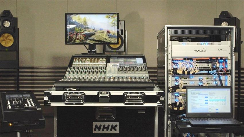
ii                                               Rep. ITU-R BS.2159-9

                                                          Foreword
The role of the Radiocommunication Sector is to ensure the rational, equitable, efficient and economical use of the radio-
frequency spectrum by all radiocommunication services, including satellite services, and carry out studies without limit
of frequency range on the basis of which Recommendations are adopted.
The regulatory and policy functions of the Radiocommunication Sector are performed by World and Regional
Radiocommunication Conferences and Radiocommunication Assemblies supported by Study Groups.

                                   Policy on Intellectual Property Right (IPR)
ITU-R policy on IPR is described in the Common Patent Policy for ITU-T/ITU-R/ISO/IEC referenced in Resolution
ITU-R 1. Forms to be used for the submission of patent statements and licensing declarations by patent holders are
available from http://www.itu.int/ITU-R/go/patents/en where the Guidelines for Implementation of the Common Patent
Policy for ITU-T/ITU-R/ISO/IEC and the ITU-R patent information database can also be found.

                                                    Series of ITU-R Reports
                                      (Also available online at http://www.itu.int/publ/R-REP/en)

      Series                                                            Title

      BO             Satellite delivery
      BR             Recording for production, archival and play-out; film for television
      BS             Broadcasting service (sound)
      BT             Broadcasting service (television)
      F              Fixed service
      M              Mobile, radiodetermination, amateur and related satellite services
      P              Radiowave propagation
      RA             Radio astronomy
      RS             Remote sensing systems
      S              Fixed-satellite service
      SA             Space applications and meteorology
      SF             Frequency sharing and coordination between fixed-satellite and fixed service systems
      SM             Spectrum management

     Note: This ITU-R Report was approved in English by the Study Group under the procedure detailed in
     Resolution ITU-R 1.

                                                                                                          Electronic Publication
                                                                                                                  Geneva, 2022
                                                          © ITU 2022
All rights reserved. No part of this publication may be reproduced, by any means whatsoever, without written permission of ITU.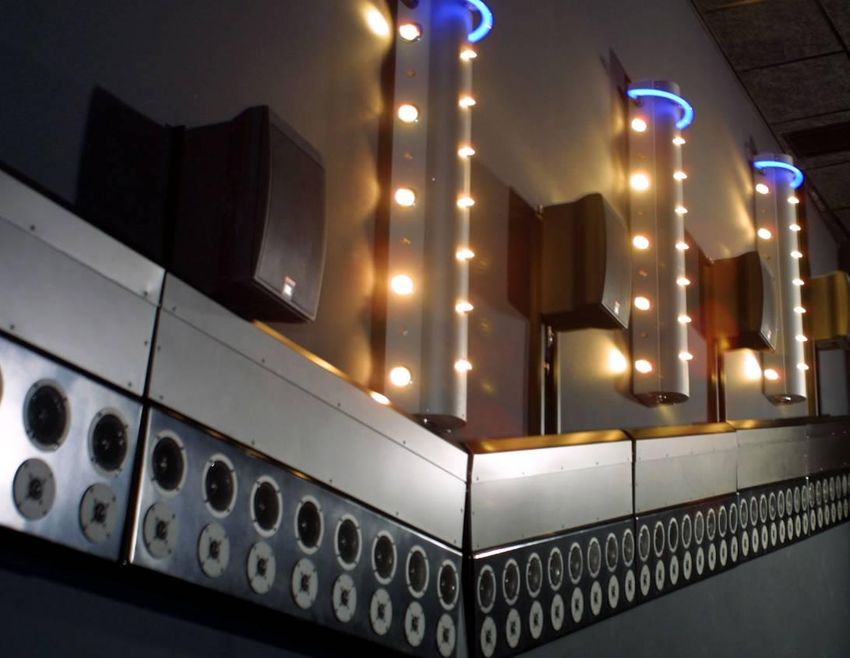
Rep. ITU-R BS.2159-9                                                                      1

                                                REPORT ITU-R BS.2159-9

        Multichannel sound technology in home and broadcasting applications
                                         (2009-2010-05/2011-10/2011-05/2012-11/2012-2013-2015-2019-2022)

                                                       TABLE OF CONTENTS
                                                                                                                                               Page

Policy on Intellectual Property Right (IPR) .............................................................................                        ii

1      Introduction ....................................................................................................................          2

2      5.1 multichannel sound system .......................................................................................                      3

3      Basic requirements of multichannel sound systems beyond the 5.1 sound system........                                                       5
       3.1        Basic requirements of the sound image ..............................................................                            5
       3.2        Basic requirement of sensation of a spatial impression ......................................                                   6
       3.3        Basic requirement of listening area ....................................................................                        6
       3.4        Basic requirement of compatibility with existing sound systems.......................                                           6
       3.5        Basic requirement of live broadcasting ..............................................................                           7

4      Multichannel sound systems beyond the 5.1 sound system under development for
       broadcasting applications ...............................................................................................                  7
       4.1        22.2 multichannel sound system (system H specified in Recommendation ITU-
                  R BS.2051)..........................................................................................................            7
       4.2        10.2 surround sound system (Type A) ................................................................                           12
       4.3        10.2 channel sound system (Type B) ..................................................................                          16
       4.4        Wave-field-synthesis ..........................................................................................                19
       4.5        Object-based audio formats ................................................................................                    24
       4.6        Hybrid channel/object-based system ..................................................................                          26

5      Multichannel sound systems in use for home audio release media ................................                                           32
       5.1        DVD audio ..........................................................................................................           32
       5.2        SACD ..................................................................................................................        32
       5.3        BD .......................................................................................................................     33

6      Multichannel sound programme production in studio for home audio ..........................                                               35
       6.1        Production of 5.1, 6.1 and 7.1 channels ..............................................................                         35
       6.2        Production of 22.2 multichannel sound ..............................................................                           35
       6.3        Production of 10.2 multichannel sound (Type A) ..............................................                                  40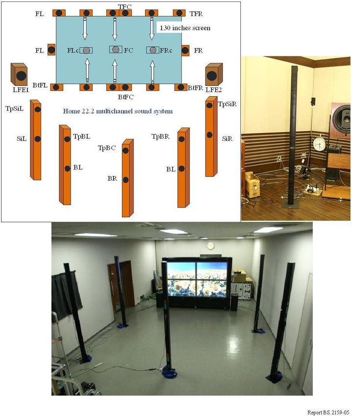
2                                                      Rep. ITU-R BS.2159-9

                                                                                                                                                Page
       6.4       Object-based post-production system .................................................................                            40
       6.5       Production of cinematic hybrid content ..............................................................                            52
       6.6       3D Virtual Microphone Systems (VMS) ............................................................                                 54

7      Quality performance of the multichannel sound systems ...............................................                                      56
       7.1       22.2 multichannel sound system .........................................................................                         56
       7.2       10.2 channel sound system (Type B) ..................................................................                            59
       7.3       Investigations into optimal speaker configurations for the hybrid
                 object/channel system .........................................................................................                  64
       7.4       Further studies on quality performance relevant to multichannel sound systems
                 ............................................................................................................................     67

8      Relevant documents concerning the multichannel sound systems developed by
       organizations outside ITU ..............................................................................................                   81
       8.1       SMPTE................................................................................................................            81
       8.2       IEC ......................................................................................................................       83
       8.3       MPEG (ISO/IEC JTC 1/SC 29/WG 11) .............................................................                                   85
       8.4       EBU ....................................................................................................................         85
       8.5       Japan ...................................................................................................................        87

1         Introduction
ITU-R has developed Recommendation ITU-R BS.775 for the 3/2 multichannel stereophonic sound
system (5.1 sound system) with and without accompanying picture. Multichannel stereo as well as
2-channel stereo audio services are widely used as part of digital broadcasting services.
Recommendation ITU-R BS.775 specifies a hierarchy of compatible multichannel sound systems to
enhance the directional stability of the frontal sound image and the sensation of spatial reality
(ambience), and each loudspeaker is set at the same height as a listener’s ears.
Some television applications with higher resolution imagery including ultra-high definition television
and high-dynamic range television specified in Recommendations ITU-R BT.2020 and BT.2100,
large screen digital imaginary (LSDI) application 1 and advanced immersive audio visual system
including 360° images, both providing wider viewing angle, may need multichannel stereophonic
sound systems that can reproduce the sound sources, which are localized at a higher position over the
listener and a lower position below the screen, and vertical movements of the sound sources. Several

1   LSDI is defined as a service whereby programmes are distributed in the form of digital signals, in real-time
    or non-real-time, for collective viewing in theatres or other group venues equipped with appropriate
    electronic projectors, to provide excellent presentation in terms of picture and sound quality, size of the
    presentation screen and presentation environment.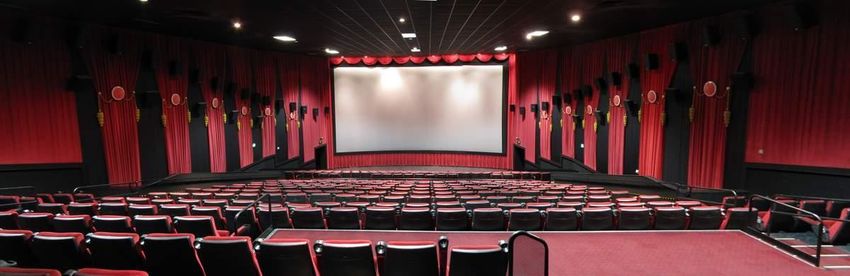
Rep. ITU-R BS.2159-9                                           3

multichannel stereophonic sound systems are currently applied or studied for higher resolution
imagery, and some of them have loudspeakers arranged above and below the viewer. There would be
value in continued studies in this area for future broadcasting applications in order to evolve beyond
the 5.1 sound system.
The advanced sound system is a system with a reproduction configuration beyond the 5.1 sound
system specified in Recommendation ITU-R BS.775 or a system that can support channel-based,
object-based, scene-based or their combination with audio-related metadata. A number of ITU-R
Recommendations relevant to the advanced sound system have been developed:
–       Recommendation ITU-R BS.1909 – The performance requirements for an advanced
        multichannel stereophonic sound system for use with or without accompanying picture
–       Recommendation ITU-R BS.2051 – Advanced sound system for programme production
–       Recommendation ITU-R BS.2127 – Audio Definition Model renderer for advanced sound
        systems.
ITU-R has also developed the following Recommendations of audio-related metadata:
–      Recommendation ITU-R BS.2076 – Audio Definition Model
–      Recommendation ITU-R BS.2094 – Common definitions for the Audio Definition Model
–      Recommendation ITU-R BS.2125 – A serial presentation of the Audio Definition Model
–      Recommendation ITU-R BS.2088 – Long-form file format for the international exchange of
       audio programme materials with metadata.
This Report contains information on the subject of multichannel sound technologies in home and
broadcasting applications beyond the 5.1 sound system specified in Recommendation ITU-R BS.775.

2       5.1 multichannel sound system
The 5.1 channel sound system has been specified in Recommendation ITU-R BS.775. The system
is widely used as a part of digital broadcasting services. It enhances the directional stability of the
frontal sound image and the sensation of spatial reality (ambience). The reference loudspeaker
arrangement is shown in Fig. 1, in which each loudspeaker is set at the same height as a listener’s
ears.
4                            Rep. ITU-R BS.2159-9

                                         FIGURE 1
         Reference loudspeaker arrangement with loudspeakers L/C/R an LS/RS
                                                  B

                                                   C
                                2                            1
                       L                                               R

                                             ß1
                                            ß2
                                                  60°

                                 100°
                                                        100°
                                     120°                  120°

    LS                                                                                           RS

                    Screen 1 HDTV - Reference distance = 3 H (2ß 1 = 33°)
                    Screen 2                           = 2 H (2ß2 = 48°)
                    H: height of screen
                    B: loudspeaker base width

           Loudspeaker       Horizontal angle from           Height        Inclination
                               centre (degrees)             (meters)        (degrees)
                C                       0                     1.2              0
               L, R                     30                    1.2              0

              LS, RS                100 ... 120              ³ 1.2     0 ... 15 d own

                                                                                   Report BS.2159-01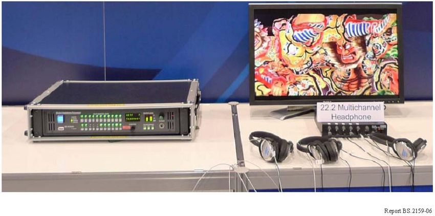
Rep. ITU-R BS.2159-9                                         5

3       Basic requirements of multichannel sound systems beyond the 5.1 sound system
The following requirements are related to the multichannel sound system beyond the current
5.1 channel sound system specified in Recommendation ITU-R BS.775.
1)      The directional stability of the frontal sound image should be maintained over the entire
        higher resolution imagery area. Coincidence of position between sound image and video
        image also should be maintained over the wide imagery area.
2)      The sound image should be reproduced in all directions around the listener, including
        elevation.
3)      The sensation of three-dimensional spatial impression that augments a sense of reality should
        be significantly enhanced. This may be achieved by the use of side and/or back, top and/or
        bottom loudspeakers.
4)      Exceptional sound quality should be maintained over wider listening area than that provided
        by current 5.1 channel sound system.
5)      Compatibility with the current 5.1 channel sound system specified in Recommendation
        ITU-R BS.775 should be ensured to an acceptable degree.
6)      Live recording, mixing and transmission should be possible.
The reasoning for the basic requirements for advanced multichannel sound systems is provided
below:

3.1     Basic requirements of the sound image
–       The directional stability of the frontal sound image should be maintained over the entire
        higher resolution imagery area. Coincidence of position between sound image and video
        image also should be maintained over the wide imagery area.
–       The sound image should be reproduced in all directions around the listener, including in the
        elevation.
Reason:
The following requirements are defined in Recommendation ITU-R BS.775 for the 5.1 channel sound
system:
–       The directional stability of the frontal sound image shall be maintained within reasonable
        limits over a listening area larger than that provided by a conventional two-channel
        stereophony.
The following requirement is also defined:
–       It is not required that the side/rear loudspeakers should be capable of the prescribed image
        locations outside the range of the front loudspeakers.
For advanced multichannel sound systems beyond the 5.1 channel sound system, the reproduction of
the sound images should be improved from the following two aspects:
−       The directional stability of the sound image come from all horizontal directions, i.e. the
        front/back and left/right directions, should be maintained within reasonable limits over the
        listening area.
−       The sound image included in the elevation directions should also be reproduced.
Therefore, the aforementioned basic requirement 2) is defined.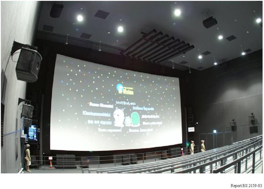
6                                     Rep. ITU-R BS.2159-9

In addition, considering advanced multichannel sound systems applied for television applications,
which have high-resolution imagery with a horizontally and vertically wide field of view,
the coincidence of the position between sound images and video images is needed over the entire
imagery area. Therefore, the aforementioned basic requirement 1) is defined.

3.2     Basic requirement of sensation of a spatial impression
–       The sensation of three-dimensional spatial impression that augments a sense of reality should
        be significantly enhanced. This may be achieved by the use of side and/or back, top and/or
        bottom loudspeakers.
Reason:
The following requirement is defined in Recommendation ITU-R BS.775 for the 5.1 channel sound
system:
–       The sensation of spatial reality (ambience) shall be significantly enhanced over that provided
        by a conventional two-channel stereophony. This shall be achieved by the use of side and/or
        rear loudspeakers.
Because each loudspeaker of the 5.1 channel sound system is set at the same height as the listener’s
ears, the sensation of spatial reality is fundamentally limited to the horizontal plane.
For advanced multichannel sound systems beyond the 5.1 channel sound system, the sensation of
spatial impression should be enhanced around the listener, including in the upward/downward
elevation sensation, reverberation and ambience. Therefore, the aforementioned basic
requirement 3) is defined.

3.3     Basic requirement of listening area
–       Exceptional sound quality should be maintained over wider listening area than that provided
        by current 5.1 channel sound system.
Reason:
The following requirement is defined in Recommendation ITU-R BS.775 for the 5.1 channel sound
system:
–       The directional stability of the frontal sound image shall be maintained within reasonable
        limits over a listening area larger than that provided by a conventional two-channel
        stereophony.
As frontal two (left and right) loudspeakers are placed for the conventional 2-channel sound system,
the listening area of the 5.1 channel sound system should be considered only for the frontal sound
image by comparing it to that of a conventional 2-channel stereophony.
To extend the basic requirement of the 5.1 channel sound system, the listening area of advanced
multichannel sound systems should be enlarged by comparing them to the 5.1 channel sound system.
Therefore, the aforementioned basic requirement 4) is defined.

3.4     Basic requirement of compatibility with existing sound systems
–       Compatibility with the current 5.1 channel sound system specified in Recommendation
        ITU-R BS.775 should be ensured to an acceptable degree.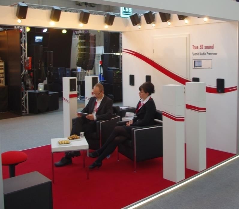
Rep. ITU-R BS.2159-9                                           7

Reason:
The following requirement is defined in Recommendation ITU-R BS.775 for the 5.1 channel sound
system:
–       Downward compatibility with sound systems providing lower number of channels (down to
        stereophonic and monophonic sound systems) shall be maintained.
The aforementioned compatibility means that, for example, the down-mixed stereophonic or
monophonic sound quality from 5.1 channel sound signals should be maintained to an acceptable
degree. To extend the basic requirement of the 5.1 channel sound system, the down-mixed 5.1 channel
or 2-channel sound quality from advanced multichannel sound signals should be maintained to an
acceptable degree for advanced multichannel sound systems.
Additionally, the compatibility should be considered from the view of programme production
facilities and exploiting the expertise of sound mixing engineer. Even in future broadcasting services,
every programme will not likely be produced by the advanced multichannel sound format. In other
words conventional sound formats, such as mono, 2-channel stereo, or 5.1 channel sound format may
be operated even in the future broadcasting depending on the programme genre or other service
requirements. Thus, broadcasters would prefer to be able to produce various sound programme
formats even in a single production studio. As a result, channel compatibility with the 5.1 channel
sound system and conventional 2-channel sound system should be considered to an acceptable
degree. It also takes advantage of sound mixing engineer’s know-how, cultivated by the 5.1 channel
sound production. Therefore, the aforementioned basic requirement 5) is defined.

3.5     Basic requirement of live broadcasting
–       Live recording, mixing and transmission should be possible.
Reason:
The following requirement is defined in Recommendation ITU-R BS.775 for the 5.1 channel sound
system:
–       Real-time mixing for live broadcast shall be practicable.
The live broadcast is the most essential factor for broadcasting services. Therefore, the
aforementioned basic requirement 6) is defined.

4       Multichannel sound systems beyond the 5.1 sound system under development for
        broadcasting applications
Several multichannel sound systems have been studied to improve the spatial impression of sound.
The following systems seem to have the capability for practical use.

4.1     22.2 multichannel sound system (system H specified in Recommendation ITU-R
        BS.2051)
The 22.2 multichannel sound system was developed by NHK (Japan Broadcasting Corporation).
It has nine channels at the top layer, ten channels at the middle layer, three channels at the bottom
layer and two low-frequency effects (LFE) channels. This system is suited to wide screens, such as
100 inch FPD displays, because it can two-dimensionally localise a sound image over the entire
screen by using three bottom channels, five middle channels and three top channels around the screen.
8 Rep. ITU-R BS.2159-9
FIGURE 2
The 22.2 multichannel sound system
TpFL TpFC TpFR
Top layer
TpC 9 channels
TpSiL TpSiR
TpBC
TpBC
TpBL TpBR
FLc FC FRc
FR
FL
Middle layer
10 channels
TV screen
SiL SiR
BtFC
BtFL BtFR
LFE1 LFE2 Bottom layer
BL BR 3 channels
BC LFE
2 channels
BtFL LEF1 BtFC LEF2 BtFR FL FLC FC FRC FR TpFL TpFC TpFR
Bottom layer SiL Middle layer SiR TpSiL TpC TpSiR
Top layer
BL BC BR TpBL TpBC TpBR
Report BS.2159-02
This system has common channels at each three layers with other multichannel systems so that its
audio can be easily down-mixed to other multichannel sound systems and has compatibility with
every multichannel sound system.
The audio characteristics and audio channel mapping for UHDTV programme production for the
22.2 multichannel sound format have been specified as system H in Recommendation ITU-R
BS.2051 and standardised by SMPTE (SMPTE 2036-2), as mentioned in § 8.1.1.
Several sound reproduction systems based on the 22.2 multichannel sound have been developed
and exhibited at more than a dozen international expositions and exhibitions, such as
World Exposition at Aichi (Japan), NAB Show in Las Vegas (United States of America), IBC
in Amsterdam (Netherlands), CEATEC Exhibition in Tokyo (Japan), Broadcast Asia in Singapore,
and Grand Exposition for Yokohama’s 150th Year. The advanced satellite digital broadcasting of
UHDTV with 22.2 multichannel sound started in Japan in December 2018.
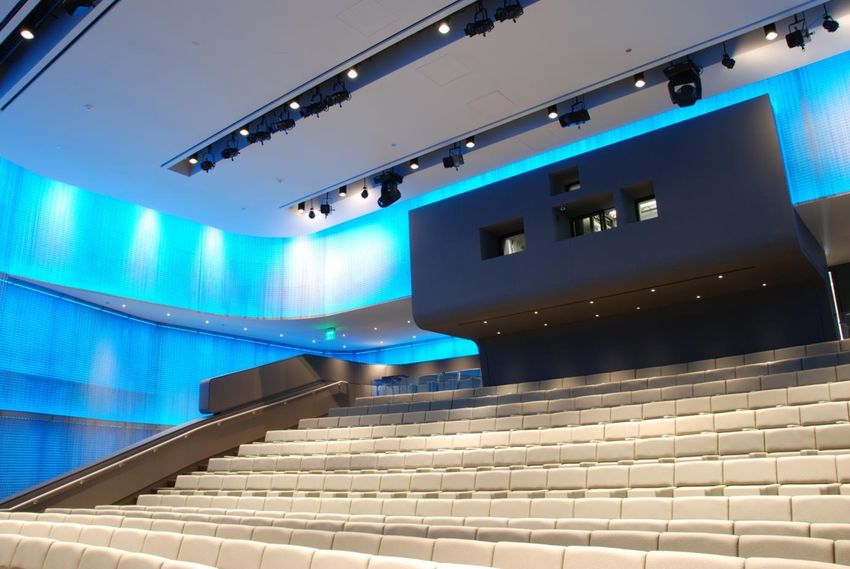
There are also permanent installations which can reproduce 22.2 multichannel sound. They are:
− One theatrical demonstration room with hundreds of seats in NHK Fureai Hall at Tokyo.Rep. ITU-R BS.2159-9 9
− One theatrical production/demonstration room with hundreds of seats, and one home theatre
demonstration room in NHK Science & Technology Research Laboratories.
− One laboratory installation in Fraunhofer IIS.
− One laboratory installation in McGill University CIRMMT.
− One laboratory installation at Qualcomm Technologies, Inc, San Diego, USA.
A large theatrical sound system with a 600 inch screen at World Exposition at Aichi, Japan in 2005
is shown in Fig. 3.
FIGURE 3
Theatrical 22.2 multichannel sound system at World Exposition held at Aichi, Japan in 2005
Post production rooms for 22.2 multichannel sound have also been installed as follows:
– Two mixing rooms in NHK broadcasting centre at Tokyo, one of which is applicable to live
production.
– Two pre-production rooms, a production studio to receive contributions and a monitoring
room for emission, in NHK broadcasting centre at Tokyo.
– One OB van.
– A mixing console for 22.2 multichannel sound is being installed in an 8K television studio
(under construction).
Home sound systems for 22.2 multichannel sound have also been developed. Figure 4 shows the
living room with 22.2 multichannel sound, where 24 loudspeakers are installed into the walls and
ceiling.10 Rep. ITU-R BS.2159-9
FIGURE 4
Living room with 22.2 multichannel sound
A tallboy type loudspeaker has been developed to reproduce three vertical channels (i.e. top, middle
and bottom channels) by a single loudspeaker. These loudspeakers are used for the home
22.2 multichannel sound system with UHDTV FPD on which compact loudspeaker units are rigged
up to reproduce frontal sound channels as Fig. 5.Rep. ITU-R BS.2159-9 11
FIGURE 5
Home 22.2 multichannel sound system using tallboy type loudspeakers
A headphone processor to provide 22.2 multichannel sound has been developed; it is shown in Fig. 6.
This processor enables listeners to enjoy an accurate immersive 3D sound with ordinary headphones.
Because the headphone processor can reproduce the 22.2 multichannel sound without the use of
loudspeakers, TV programmes with 3D sound can be efficiently produced on location in places such
as an OB van.12 Rep. ITU-R BS.2159-9
FIGURE 6
22.2 multichannel sound headphone processor
4.2 10.2 surround sound system (Type A)
4.2.1 Background
The Immersive Audio Laboratory is a part of the Integrated Media Systems Center at the University
of Southern California and its practitioners have worked since the mid-1990s in the development of
multichannel sound, especially 10.2-channel sound. This sound system is a logical extension of
Recommendation ITU-R BS.775 and its 5.1-channel layout. Although called 10.2 as shorthand,
it actually employs 14 electrical channels, explained below. 10.2 describes the number of loudspeaker
locations, since some loudspeaker channels can be combined into one physical location.
4.2.2 Highlights
There are eight permanent installations of 10.2 channel sound as of February 2010. They are:
− Two cinemas with hundreds of seats each. Note that these use a variant on the basic system,
designed specifically for cinemas (typ. > 2 500 cu. m.), where surround arrays are used for
left, right, and rear surround, along with point sources for left and right surround.
− One home theatre demonstration room operating in an audio-video store. In operation for
many years and used virtually continuously to demonstrate the advantages of more sound
channels to the public.
− One high-power installation at USC’s Institute for Creative Technologies, funded by
DARPA.
− Two laboratory installations in Ronald Tutor Hall at USC.
− One installation at Inha University, Incheon, Kore.
− One installation in a private home.
In addition, more than a dozen temporary exhibitions have been made on four continents
(North America, South America, Europe, and Asia).Rep. ITU-R BS.2159-9 13
There are more than 20 items of produced programme material. Since 10.2-channel sound is
a playback platform, not a recording/playback system, a wide variety of methods of recording have
been employed, from classic ones, to completely constructed spaces using advanced digital signal
processing algorithms.
The system is scalable from very small listening rooms to cinemas. Changes are made in the physical
system to accommodate the range of conditions encountered and its calibration, and the focus of the
work has been in deriving the maximum interchangeability among the various size installations.
There is no recalibration or mixing necessary to scale from the smallest to the largest space.
The loudspeaker layout was chosen considering physical acoustics of spaces to be reproduced;
psychoacoustics of multichannel listening; and the desires of composers, sound designers, and other
interested parties. Publications are available detailing these choices.
4.2.3 The loudspeaker channel layout
The loudspeaker channel layout starts with standard 5.1:
− L –30° in plan view, approximately 0° in elevation (raised slightly for line-of-sight in multi-
row listening for direct path sound, or the L screen channel in cinemas which are 2/3 of the
way up the height of the motion-picture screen to the high-frequency section for instance).
Reference point is the centre of the listening area.
− R +30° in plan, same elevation and reference position as L.
− C 0° in plan (straight ahead), same elevation and reference position as L.
− LS direct –110°±10° in plan, same elevation and reference position as L.
− RS direct +110°±10° in plan, same elevation and reference position as L.
To which are added the following:
− Left Wide (LW) –60° in plan, same elevation and reference position as L.
− Right Wide (RW) +60° in plan, same elevation and reference position as L.
− LS diffuse. For “small” rooms of a typical room volume of 85 cu. m: typically a dipole type
loudspeaker radiation pattern (low bass excepted) at –110°±10° in plan, elevated above the
LS direct loudspeaker. For “large” rooms (cinemas) which are typically >1 000 cu. m:
typically a surround array composed of four to twelve loudspeakers laid out for uniform
sound level coverage of the listening area.
− RS diffuse. For “small” rooms as above: typically a dipole-type loudspeaker radiation pattern
(low bass excepted) at +110°±10° in plan, elevated above the RS direct loudspeaker. For
“large” rooms (cinemas) as above: typically a surround array composed of four to twelve
loudspeakers laid out for uniform sound level coverage of the listening area.
− Back Surround (BS): For “small” rooms as above: +180° in plan, same elevation and
reference position as L.
− Left Height (LH): –45° in plan and elevated +45° (or whatever is practical) above the
listening plane.
− Right Height (RH): +45° in plan and elevated +45° (or whatever is practical) above the
listening plane.
− L Sub: Systems employ bass management. Bass below the operating frequency range of all
of the left channel loudspeakers (L, LH, LW, LS direct, LS diffuse) and C are added together
at equal level and L LFE is added in at +10 dB in-band gain. Typical crossover frequency is
25-50 Hz. Typical L LFE low pass filter frequency (brick wall) is 120 Hz. The combined
signals are sent to one or more subs located left of the listener. In cinemas they may be in the
left front corner. In small rooms they may be on the left side of the room.14 Rep. ITU-R BS.2159-9
− R Sub: Bass below the operating frequency range of all of the right channel loudspeakers (R,
RH, RW, RS direct, RS diffuse) and BS are added together at equal level and R LFE is added
in at +10 dB in-band gain. Typical crossover frequency is 25-50 Hz. Typical R LFE low pass
filter frequency (brick wall) is 120 Hz. The combined signals are sent to one or more subs
located right of the listener. In cinemas they may be in the right front corner. In small rooms
they may be on the right side of the room.
The consolidated positions of Left Surround direct and diffuse radiators, and Right Surround direct
and diffuse radiators (applicable in “small” rooms), result in 10.2 total speaker locations. The system
thus requires 14 electrical channels. Additionally, two channels of a sixteen-channel layout are
reserved for Hearing Impaired and Visually Impaired descriptive service channels.
4.2.4 Standardization
By following the outlined speaker locations and sound calibration methods, 20 installations have been
made to sound as similar as possible. 10.2 is recognized as a format in Apple Quicktime and in
SMPTE Digital Cinema standards. It has been implemented by one audio workstation manufacturer,
and another is expected to join.
FIGURE 7
Diagram of speaker layout for 10.2
Top view
C
L R
+45°H +45°H
RH
LH
45°
RW
LW
60°
30°
110°
Sub
Sub
L
R
180°
LS
RS
Direct and Direct and
diffuse diffuse
radiators radiators
BS
Report BS.2159-07Rep. ITU-R BS.2159-9 15
FIGURE 8
Typical “small room” installation schematic
Report BS.2159-0816 Rep. ITU-R BS.2159-9
4.3 10.2 channel sound system (Type B)
4.3.1 Background
In the Republic of Korea, a 10.2 channel audio system was developed and this multichannel system
was standardized as “Audio Signal Formats for Ultra High Definition (UHD) Digital TV” in the
Republic of Korea, TTAK.KO-07.0098 in 2011. This standard has been developed based on
3/4 loudspeaker arrangement of Recommendation ITU-R BS.775 for backward compatibility with
the conventional system. The specific information about this system is described below. It is
somewhat different from 10.2 surround sound system (Type A) of § 4.2.
4.3.2 The loudspeaker channel layout
Firstly, the terms for this layout are defined. The loudspeaker layout is composed of three heights,
layers:
– middle layer: the height which is an ear position of listener;
– top layer: the height which is a position over the listener’s head;
– bottom layer: the height which is a position under the listener’s leg.
The 10.2 channel loudspeakers are defined as below.
TABLE 1
Channel definition of 10.2 channel
Channel Label Definition
L Left channel/signal/speaker Front left position on middle layer
R Right channel/signal/speaker Front right position on middle layer
LB Left Back channel/signal/speaker Rear left position on middle layer
RB Right Back channel/signal/speaker Rear right position on middle layer
C Centre channel/signal/speaker Front centre position on middle layer
Left Low Frequency Effect
LFE1 Left side on bottom layer
channel/signal/speaker
LS Left Side channel/signal/speaker Left position on middle layer
RS Right Side channel/signal/speaker Right position on middle layer
LH Left Height channel/signal/speaker Front left position on top layer, elevated
RH Right Height channel/signal/speaker Front right position on top layer, elevated
CH Centre Height channel/signal/speaker Rear centre position on top layer, elevated
Right Low Frequency Effect
LFE2 Right side on bottom layer
channel/signal/speaker
Then the 10.2 channel loudspeakers are arranged as below.Rep. ITU-R BS.2159-9 17
FIGURE 9
The 10.2 channel loudspeaker layout
TABLE 2
Channel arrangements of 10.2 channel
Channel Azimuth Remark
C 0° –
L, R ±30° left and right each
LS, LB, at left and right,
±60° ~ 150°
RS, RB two channels each
CH 90° ~ 135°H in that range
LH, RH ±30° ~ 45° & 30° ~ 45°H horizontally and vertically each
The loudspeaker channel layout starts with the 5.1 and 3/4 loudspeaker arrangement of
Recommendation ITU-R BS.775:
– L–30° in middle layer, 0° in elevation. Reference point is the centre of the listening area.
– R+30° in middle layer, same elevation and reference position as L.
– C0° in middle layer, same elevation and reference position as L.
– LS and LB-60~–150° in middle layer, same elevation and reference position as L.
– RS and RB+60~+150° in middle layer, same elevation and reference position as L.
To which are added the following:
– Left Height (LH)-30~–45° in middle layer with +30~+45° elevated. Reference point is the
ear level of listener and this channel positioned in top layer.
– Right Height (RH)+30~+45° in middle layer with +30~+45° elevated and reference position
as LH.
– Centre Height (CH)+90~+135° elevated and reference position as LH.
– LFE1: Systems employ bass management. Bass below the operating frequency range of all
of the left channel loudspeakers (L, LS, LB, LH) C, and CH are added together at equal level;
and18 Rep. ITU-R BS.2159-9
− LFE2: Bass below the operating frequency range of all of the right channel loudspeakers
(R, RS, RB, RH), C and CH are added together at equal level.
So the resulting arrangement is depicted in Figs 10 and 11 below.
FIGURE 10
Middle layer and top layer of 10.2ch loudspeaker layout
FIGURE 11
Top layer and bottom layer of 10.2ch loudspeaker layout
4.3.3 Recommended arrangement of 10.2 channel
The outlined speaker location as the recommended arrangement of 10.2 channel audio system is as
follows:Rep. ITU-R BS.2159-9 19
TABLE 3
Specific channel arrangements of 10.2 channel
Channel Azimuth
LS –90°
RS 90°
LB –135°
RB 135°
LH –45°/45°H
RH 45°/45°H
CH 135°H
FIGURE 12
Specific channel arrangements of 10.2 channel
4.4 Wave-field-synthesis
Wave-field-synthesis (WFS) was invented by the Delft University of Technology, Netherlands in
1989. In the European project CARROUSO components for the complete chain including recording,
coding, transmission, decoding, and sound reproduction were developed. Since then WFS has been
refined to deliver truly immersive sound. Application areas include cinema (with a priority on
combination with 3D video), theme parks, virtual reality (VR) installations (in combination with 3D
audio) and, in the long run, home theatres. In February 2003 the first cinema using this system started
daily operation (Ilmenau, Germany). In 2004 the first WFS system was installed in a sound stage in
Studio City, CA. Since 2008, the Chinese 6 Theatre and the Museum of Tolerance in Los Angeles
have been equipped with WFS sound systems. These systems are also used in themed environments.
Commercial examples of IOSONO GmbH (a spinoff of Fraunhofer IDMT) include the installation in
the 4D cinema at the Bavaria Filmstadt (Munich), the Odysseum Science Adventure Park (Cologne),
and the “Haunted Mansion” at Disney World (Orlando). Virtual reality installations at the University
of Surrey and the Technical University of Ilmenau use WFS with two loudspeaker arrays in the front
to enable the proper reproduction of elevation. These two systems also use stereoscopic video
projection. An extension of WFS with additional loudspeakers above the listeners was presented at
“the 2008 Expo” in Saragossa.20 Rep. ITU-R BS.2159-9
FIGURE 13
WFS sound system in the German cinema “Linden lichtspiele ilmenau”
Report BS.2159-13
WFS is an object-oriented approach to accurately recreate a replication of a sound field using the
theory of waves and of the generation of wave fronts. This concept is best explained by the well-
known Huygens principle: points on a wave front serve as individual point sources of spherical
secondary waves. This principle is applied in acoustics by using a large number of small and closely
spaced loudspeakers (loudspeaker arrays). The driving signal is calculated for each of the
loudspeakers in real time at the reproduction site. The number of loudspeakers is independent from
the number of transmission channels and only related to the size of the reproduction room.
Loudspeaker arrays controlled by WFS reproduce wave fields that originate from any combination
of (virtual) sound sources like an acoustic hologram. When manipulated properly, the system
recreates wave fronts approaching perfect temporal, spectral and spatial properties throughout the
listening room.Rep. ITU-R BS.2159-9 21
FIGURE 14
Working principle of WFS
Report BS.2159-14
Three representations of sound sources are possible in WFS (see Fig. 15). In the first two, virtual
sound sources can be placed behind the loudspeaker arrays (so-called point sources) as well as in
front of loudspeaker arrays (so-called focused sources). In the case of sound sources in front of the
array, the array radiates convergent waves toward a focus point, from which divergent waves
propagate into the listening area. The third type is the so-called plane waves. Plane waves come from
the same angular direction for all positions in the listening space.
The other commonly used channel-oriented sound reproduction approaches require a well-defined
loudspeaker setup, i.e. the number and positions of the loudspeakers are predefined. In the mastering
process the target setup must be determined and the loudspeaker signals prepared in a way that allows
them to perfectly fit the assumed setup. This implies that it is difficult to feed the generated signals
into another sound system.
This problem can be solved by the object-oriented sound reproduction paradigm, which was develop
for WFS but which is not restricted to it. In this method, the audio content is represented as audio
objects containing the pure audio content together with metadata describing the position of the object
in real time along with the properties of the audio object like directivity. On the rendering site the
driving signal for each individual loudspeaker is calculated taking into account its exact position in
the reproduction room. Besides the positioning of direct sound, a position-dependent calculation of
early reflections and diffuse reverberations is possible, which enables the generation of realistic but
also artificial spatial environments. Through the availability of the direct sound of each source and a
parametric description of the properties of the room, an optimal reproduction can be adapted to the
given spatial environment. This can be a WFS setup of any size (and number of loudspeakers) but
also an arbitrary loudspeaker configuration. Increasing the number of loudspeakers increases the size
of the sweet spot and makes the sound sources more stable. This results in an increased freedom when
deciding which loudspeaker setup to install, because the actual loudspeaker signals are calculated at
the reproduction site through a process called rendering.22 Rep. ITU-R BS.2159-9
FIGURE 15
Reproduction of point sources, focused sources and plane waves
Point source A
Plane wave
Point source B
Focused source
Report BS.2159-15
WFS overcomes the restrictions of a sweet-spot and enable the location of sound objects at any
position outside and inside the reproduction room without problems of phase or sound coloration.
All formats mentioned in §§ 4.1, 4.2 and 5 can be reproduced using WFS by the concept of virtual
loudspeakers enabling an enlarged sweet-spot for any content already produced.
4.4.1 Object-based multichannel audio system
This system was developed based on the principles of wave-field synthesis, originally invented by
TU Delft and explored in the European project CARROUSO2. In CARROUSO the MPEG-4 BIFS
was used to represent the audio data. For commercial applications this very flexible format proved to
be too complex (in terms of storage requirements and computing power) and therefore a less
expensive version of the file format had to be developed. With the intention of keeping the perceptual
properties of wave-field synthesis, a system for flexible 3D speaker layouts was developed in
Germany3.
A complete production and reproduction chain based on the object-based paradigm is available. More
than 20 commercial and demonstration installations of systems exist worldwide (e.g. Chinese 1
Multiplex Theater and Chinese 6 Multiplex Theater in Hollywood, Los Angeles). Virtual reality
installations at the University of Surrey and the Technical University of Ilmenau use WFS with two
loudspeaker arrays in the front to enable the proper reproduction of elevation. These two systems also
use stereoscopic video projection. An extension of WFS with additional loudspeakers above the
2 Partners in CARROUSO: Fraunhofer IDMT (Federal Republic of Germany), IRT (Federal Republic
of Germany), University of Erlangen (Federal Republic of Germany), France Telecom (France), IRCAM
(France), Thales (France), TU Delft (Netherlands), Aristotle University of Thessaloniki (Greece),
EPFL (Switzerland), Studer (Switzerland).
3 By IOSONO GmbH Erfurt (Federal Republic of Germany) and Fraunhofer IDMT Ilmenau
(Federal Republic of Germany).Rep. ITU-R BS.2159-9 23
listeners was presented at “the 2008 Expo” in Saragossa. A 3D setup with two layers of loudspeakers
was shown at Prolight + Sound 2011 in Frankfurt, Germany. A few installations are shown here to
illustrate the diversity that can be realized using the object-based audio system. Content can be
exchanged between all these systems.
FIGURE 16
Installation with 64 loudspeakers at the Chinese Multiplex Theater, Hollywood
Report BS.2159-16
FIGURE 17
Setup with 2 flexible layers of 34 loudspeakers presented at a trade show
Report BS.2159-1724 Rep. ITU-R BS.2159-9
FIGURE 18
Wave-field synthesis based setup at Peltz Theatre, Beverly Hills
Report BS.2159-18
A headphone processor to process object-based scene description for dynamic binaural headphone
reproduction has been developed. The headphone processor can be used to simulate several
loudspeaker layouts to monitor the auditory scene as it would be rendered in a real loudspeaker
setup.
4.5 Object-based audio formats
The other commonly used channel-oriented sound reproduction approaches require a well-defined
loudspeaker setup, i.e. the number and positions of the loudspeakers are predefined. In the mastering
process the target setup must be determined and the loudspeaker signals prepared in a way that allows
them to perfectly fit the target setup. This implies that it is difficult to feed the generated signals into
another sound system. This problem can be solved by the object-based sound reproduction paradigm,
which was develop for WFS but which is not restricted to it.
In an object-oriented system the audio content is created independently of any specific loudspeaker
layout. The audio content is represented as audio objects containing the pure audio content, together
with metadata describing the position of the audio object along with the properties of the audio object
such as directivity in real time.Rep. ITU-R BS.2159-9 25
On the rendering site the driving signal for each individual loudspeaker is calculated, taking into
account its exact position in the reproduction room. Such representations can be rendered in real time
to loudspeaker setups from 5 to more than 500 speakers. The setups do not have to be regular or in a
specific layout but standard layouts can easily be supported (as shown in Fig. 19). Furthermore, the
auditory scene can be scaled to the current screen size and size of the audience area in a reproduction
venue. In that way the content can be transferred between different cinemas as well as to domestic-
size screens. Due to the adaptive rendering, loudspeakers do not have to be placed in a specific
relationship to the screen. The setup of a system in a home environment becomes flexible and
acceptable. This results in an increased freedom when deciding which loudspeaker setup to install,
because the actual loudspeaker signals are calculated at the reproduction site through a process called
rendering.
WFS overcomes the restrictions of a sweet-spot and enables the location of sound objects at any
position outside and inside the reproduction room without problems of phase or sound coloration,
if an appropriate number of loudspeakers are installed. All current or future multichannel formats can
be reproduced using WFS by the concept of virtual loudspeakers enabling an enlarged sweet-spot for
any content already produced.
FIGURE 19
Comparison between channel based and object-based production system
Channel-based Channel-based with Object-based
object-based
production
Distribution format Distribution format
(audio + metadata) (audio + metadata)
Rendering for
standard setups
Distribution format Distribution format
(audio data) (audio data)
Decoding Decoding Decoding
(optional) (optional) (optional)
Blind up/downmix Blind up/downmix Rendering for
individual setups
Loudspeaker setup
Loudspeaker setup
Loudspeaker setup
Position correction Position correction
Loudspeaker filter Loudspeaker filter Loudspeaker filter
Reproduction system Reproduction system Reproduction system
Report BS.2159-1926 Rep. ITU-R BS.2159-9
4.5.1 Rendering and reproduction of object-based audio
Depending on the specified speaker setups the algorithm scales the reproduction of an object-based
scene. If only a few loudspeakers are available, a rendering with comparable quality to any
multichannel format is the result. On the other end, if a wave-field synthesis loudspeaker setup is
available, wave-field synthesis is used for the rendering process. Due to its flexibility loudspeaker
signals for multichannel layouts like 22.2, 10.2, 9.1 or 5.1 can be rendered in real time directly using
the production or reproduction tools. Using the spatial audio processor a rendering with a specific
adaptation to a venue is possible and loudspeaker setups from 5 to 500 speakers are possible. Such a
system can reproduce different source types which are known from wave-field synthesis. Point
sources enable the perception of a fixed source position for the whole audience area. Plane waves
enable the perception of a fixed source direction for the whole audience area. Depending on the
number of loudspeakers the focusing can be used to create a source position between loudspeaker and
listener.
4.6 Hybrid channel/object-based system
4.6.1 Introduction
Recently there has been considerable interest in alternative spatial audio description methods in the
audio industry. The developers of this hybrid channel/object based system had long recognized the
potential benefits of moving beyond “speaker feeds” as a means for distributing spatial audio.
At a high level, there are three main spatial audio description formats:
– Speaker feed – the audio is described as signals intended for loudspeakers at nominal speaker
positions. Binaural audio is a special case where the speakers are located at the left and right
ears.
– Model- or Object-based description – the audio is described in terms of a sequence of audio
events at specified positions.
– Sound field description – describes the acoustic sound field, not a set of sound sources
(e.g. objects or speakers). For example, an acoustic sound field can be described within a
region using spherical harmonics.
The speaker-feed format is the most common because it is simple and effective. If the playback
system is known in advance, mixing, monitoring and distributing a speaker feed description that
identically matches the target configuration provides the highest fidelity. However, in most cases the
playback system is not known and can only be assumed to conform to a general standard e.g. stereo,
5.1. Deviation from nominal speaker placement results in distortions of the spatial information;
however timbre is generally well preserved. For content where spatial accuracy is not critical, the
speaker-feed format is effective. There is a large body of excellent stereo and multi-channel audio
programmes that support this statement.
The object-based description is the most adaptable because it makes no assumptions about the
rendering technology and is therefore most easily applied to any rendering technology.
This adaptability allows the listener the freedom to select a playback configuration that suits their
individual needs or budget – with the audio rendered specifically for their chosen configuration. The
model-based description efficiently captures high resolution spatial information and enables accurate
and lifelike reproduction that is particularly effective for discrete audio images. The object-based
model includes much information beyond position, including size.
This system combines these two scene description methods.Rep. ITU-R BS.2159-9 27
Hybrid system
A hybrid channel- and object-based audio system provides all the benefits of a traditional
speaker-based format:
– high timbre control and fidelity,
– direct control of speaker signals when desired,
– efficient transmission of dense audio ambiences and textures,
– traditional authoring options that allow mixers to make use of their experience and expertise,
while incorporating the new capabilities at their own pace,
and extends the capabilities to include the following benefits
– more immersion and envelopment,
– increased spatial resolution, e.g. an audio object can be dynamically assigned to any one or
more loudspeakers within a traditional surround array,
– ability to effectively bring sound images off screen,
– single inventory distribution compatible with effective adaption to alternative rendering
modes including 5.1 and 7.1,
– familiar surround mixing paradigm. The front end of the mixing process is identical to
existing tools. The rendering step is delayed until after distribution.
This system has been introduced into the cinema marketplace under the trade name “Dolby Atmos”.
4.6.2 System design in theatres and LSDI venues
The recommended layout of speakers for this hybrid system remains compatible with existing cinema
systems and LSDI venues, which is important so as not to compromise the playback of existing 5.1
and 7.1 channel-based formats. In the same way that the intent of the content creator must be
preserved with the introduction of this system, the intent of mixers of 7.1 and 5.1 surround content
must equally be respected. This includes not changing the positions of existing primary front channels
in an effort to heighten or accentuate the introduction of new speaker locations. This hybrid format is
capable of being accurately rendered in the cinema to speaker configurations such as 7.1, allowing
the format (and associated benefits) to be used in existing venues with no change to amplifiers or
loudspeakers.
Different speaker locations can differ in effectiveness depending on the room design, and therefore
the industry appears to agree that there is not an ideal number or placement of channels. As a result,
this hybrid format is adaptable and able to play back accurately in a variety of rooms, whether they
have a limited number of playback channels or many channels with highly flexible configurations.
Figure 20 shows a diagram of suggested speaker locations in a typical auditorium. The reference
position referred to in the document corresponds to a position two-thirds of the distance back from
the screen to the rear wall, on the centre line of the screen.28 Rep. ITU-R BS.2159-9
FIGURE 20
Recommended speaker locations
Screen speakers
The developers have studied the perception of a higher speaker density (both vertical and horizontal)
in the screen plane. It was found that additional speakers behind the screen, such as Left Centre (Lc)
and Right Centre (Rc) screen speakers (in the locations of Left Extra and Right Extra channels in
70 mm film formats), can be beneficial in creating smoother pans across the screen, while additional
layers of vertical speakers provide little benefit in particular in the context of stadium seating
configurations. Consequently, for cinemas and LSDI venues it is recommended to install these
additional speakers, particularly in auditoria with screens greater than 12 m (40 ft) wide. All screen
speakers should be angled such that they are aimed toward the reference position. The recommended
placement of the subwoofer behind the screen remains unchanged, including maintaining asymmetric
cabinet placement, with respect to the centre of the room, to prevent stimulation of standing waves.Rep. ITU-R BS.2159-9 29
Figure 21 shows a diagram of suggested speaker locations at the screen. For home viewing
applications, screen height speakers have been introduced in the past (e.g. in the Dolby ProLogic 2z
format) as they offer a convenient trade-off between addition of some height dimension into the mix
and ease of installation.
FIGURE 21
Recommended speaker locations (screen, side surrounds, and top surrounds)
Surround speakers
Ideally, surround speakers should be specified to handle an increased SPL for each individual speaker,
and also with wider frequency response and the ability to provide uniform coverage throughout the
seating area where possible.
As a rule of thumb for an average-sized theatre, the spacing of surround speakers should be between
2 and 3 m (6' 6" and 9' 9"), with Left and Right Surround speakers placed symmetrically. However,
the spacing of surround speakers is most effectively considered as angles subtended from a given
listener between adjacent speakers, as opposed to using absolute distances between speakers.
For optimal playback throughout the auditorium, the angular distance between adjacent speakers
should be 30° or less, referenced from each of the four corners of the prime listening area. Good
results can be achieved with spacing up to 50°. For each surround zone, the speakers should maintain
equal linear spacing adjacent to the seating area where possible. The linear spacing beyond the
listening area, such as between the front row and the screen, can be slightly larger.
Side surrounds
Additional side surround speakers should be mounted closer to the screen than the currently
recommended practice of starting approximately one-third of the distance to the back of the
auditorium. These speakers are not used as side surrounds during playback of 7.1 or 5.1 soundtracks,
but they will enable smooth transition and improved timbre matching when panning objects from the
screen speakers to the surround zones.30 Rep. ITU-R BS.2159-9
To maximize the impression of space, the surround arrays should be placed as low as is practical,
subject to the following constraints: the vertical placement of surround speakers at the front of the
array should be reasonably close to the height of the screen-speaker acoustic centre, and high enough
to maintain good coverage across the seating area according to the directivity of the speaker.
The vertical placement of the surround speakers should be such that they form a straight line from
front to back, and (typically) slanted upward so the relative elevation of surround speakers above the
listeners is maintained toward the back of the cinema as the seating elevation increases, as shown in
Fig. 22. In practice, this can be achieved most simply by choosing the elevation for the front-most
and rear-most side surround speakers, and placing the remaining speakers in a line between these
points.
The distance between side surround speakers should be determined based on the guiding principles
at the start of this section.
FIGURE 22
Recommended side wall and ceiling speaker locations
Rear surrounds
The number of rear surround speakers, and the distance between them, should be determined based
on the same guiding principles as for the side surrounds. The back-wall speakers should have
approximately the same linear spacing as the side surrounds adjacent to the seating area, although
it may be necessary to slightly increase the density of back surrounds in order to meet the angular
requirements. Such an increase in density can also be an advantage for power handling of the left and
right rear surround zones, which are typically half the length of the side surround zones.
Top surrounds
Overhead (or top surround) speakers should be in two arrays from the screen to the back wall,
nominally in alignment with the Lc and Rc screen channels of a typical auditorium, where the screen
width is effectively the width of the theatre and the screen top is near the ceiling. They should always
be placed symmetrically with respect to the centre of the screen. The top surrounds should have the
same design characteristics as the side surrounds to maintain timbre matching.You can also read