MOCLORA-AN ARCHITECTURE FOR LEGGED-AND-CLIMBING MODULAR BIO-INSPIRED ROBOTIC ORGANISM - MDPI
←
→
Page content transcription
If your browser does not render page correctly, please read the page content below
biomimetics

Article
MoCLORA—An Architecture for Legged-and-Climbing
Modular Bio-Inspired Robotic Organism
Carlos Prados * , Miguel Hernando                    , Ernesto Gambao         and Alberto Brunete

                                         Centre for Automation and Robotics (CAR UPM-CSIC), Universidad Politécnica de Madrid, 28040 Madrid, Spain
                                         * Correspondence: c.prados@upm.es; Tel.: +34-625753443

                                         Abstract: MoCLORA (Modular Climbing-and-Legged Robotic Organism Architecture) is a software
                                         framework for climbing bio-inspired robotic organisms composed of modular robots (legs). It is
                                         presented as a modular low-level architecture that coordinates the modules of an organism with any
                                         morphology, at the same time allowing exchanges between the physical robot and its digital twin.
                                         It includes the basic layers to control and coordinate all the elements, while allowing adding new
                                         higher-level components to improve the organism’s behavior. It is focused on the control of both
                                         the body and the legs of the organism, allowing for position and velocity control of the whole robot.
                                         Similarly to insects, which are able to adapt to new situations after the variation on the capacity of any
                                         of their legs, MoCLORA allows the control of organisms composed of a variable number of modules,
                                         arranged in different ways, giving the overall system the versatility to tackle a wide range of tasks
                                         in very diverse environments. The article also presents ROMERIN, a modular climbing and legged
                                         robotic organism, and its digital twin, which allows the creation of different module arrangements for
                                         testing. MoCLORA has been tested and validated with both the physical robot and its digital twin.

                                         Keywords: modular robot; legged-and-climbing robot; control architecture; robotic organism; digital twin

                                         1. Introduction
                                               In recent years, the interest in legged robots has been increasing, and, as a consequence,
Citation: Prados, C.; Hernando, M.;
                                         impressive results have been achieved thanks to the advances in control techniques. Legged
Gambao, E.; Brunete, A.
                                         locomotion, although less energy-efficient than wheels, allows flexibility and versatility
MoCLORA—An Architecture for
Legged-and-Climbing Modular
                                         that is essential in unstructured environments [1]. The climbing ability allows legged robots
Bio-Inspired Robotic Organism.
                                         to carry out inspection tasks in facilities such as wind generators, large buildings, aircraft
Biomimetics 2023, 8, 11. https://
                                         fuselages, nuclear power plants, tunnels, and cooling towers [2].
doi.org/10.3390/biomimetics8010011             Legged robots often imitate legged animals, such as humans or insects, as an example
                                         of biomimicry [3,4]. In the search for similarity with animals, legged robots are endowed
Academic Editor: Lily Chambers
                                         with a high number of degrees of freedom (DOF), and consequently, they are difficult
Received: 18 October 2022                to control. This complex task deals with the coordination of all of them to achieve the
Revised: 19 December 2022                desired movements while ensuring the stability and safety of the entity. Legged-and-
Accepted: 21 December 2022               climbing (L&C) robots add an extra problem: the need to have a gripping system, such
Published: 27 December 2022              as suction cups, vacuum systems, grippers, or magnets. With the aim of reducing control
                                         complexity and increasing the range of target applications, in this article we propose the
                                         concept of the modular L&C robotic organism and its body position and velocity control
                                         through a modular approach, in such a way that each leg (module) is controlled by a single
Copyright: © 2022 by the authors.
                                         controller that is coordinated by a higher agent. L&C robots present superior mobility in
Licensee MDPI, Basel, Switzerland.
                                         complex environments with discontinuous support surfaces and higher failure tolerance
This article is an open access article
                                         during static stable locomotion [5]. In fact, they have developed extraordinary robustness
distributed under the terms and
conditions of the Creative Commons
                                         through redundancy and fast adaptation. Furthermore, they are able to act in harsh
Attribution (CC BY) license (https://
                                         conditions and environments where operators or other locomotion types cannot. Most of
creativecommons.org/licenses/by/
                                         the recent research projects in the field of civil transportation infrastructures are focused
4.0/).                                   on using exclusively UAVs (drone) technology in a different configuration. However, they

Biomimetics 2023, 8, 11. https://doi.org/10.3390/biomimetics8010011                                   https://www.mdpi.com/journal/biomimetics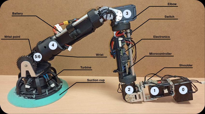
Biomimetics 2023, 8, 11                                                                                            2 of 19

                          present several drawbacks in real massive applications: a limited flying capability that
                          makes it extremely difficult to avoid air turbulences during inspection with running traffic
                          (especially in tunnels), limited navigation ability in complex environments with difficult
                          access (inner parts of bridges), and lack of regulation of free drones flying. On the other
                          hand, L&C robots can be used in those applications where it is required to contact the
                          environment. For example, they can be used for material analysis with ultrasonic sensors.
                          Other advantages over drones are the payload capacity, autonomy with high payloads,
                          and safety (can be improved with lifelines).
                               Inspiration for our system is found in the world of insects in a particular way. In these
                          animals, we can see how the brain coordinates the movement of the different extremities,
                          each of them trying to cooperate to move as a single entity [6]. If, for whatever reason,
                          the number of extremities or the capacity of action of some of them varies, the insect is able
                          to adapt to the new situation.
                               When comparing different animals in nature, it is remarkable that despite substantial
                          differences in structure, leg systems of all kinds rely only on a small set of different gaits.
                          One approach is the generation of predefined motion patterns [7–9]. However, it will
                          cause movements that are neither optimal nor recommended for the system proposed
                          in this article, since the number of legs and their position may vary. Another common
                          approach is the use of central pattern generators (CPG), which produces rhythmic patterned
                          outputs [10–12]. In this article, we do not cover the locomotion analysis, and we focus our
                          work on leg coordination for body positioning in the same way that animals behave. That
                          is, when the organism tries to move the body, all the elements of the organism support
                          that movement.
                               In the literature, a modular robot is one capable of changing its shape to adapt to dif-
                          ferent tasks and environments [13,14]. They are systems made up of identical components
                          in such a way that they work cooperatively to achieve a common goal. A combination
                          of several modules that are encapsulated in a larger system capable of carrying out more
                          complex tasks is usually defined as a robotic organism, that is, a living system that functions
                          as an individual entity. The objective of employing a robotic organism of simpler robots
                          with reduced complexity is to increase robustness and adaptation ability [15]. With the
                          aim of developing a L&C robot intended to be used in a large number of environments,
                          and to cover as many tasks as possible, in this article we propose an architecture for the
                          body position and velocity control of this type of robots, where the number and disposition
                          of modules or legs are variable. Unlike self-configurable modular robots, whose shape may
                          vary dynamically during operational time, the proposed modular robot is intended to deal
                          with a morphology change previously to operations (manually reconfigurable robot).
                               We focus our work on coordinating the modules as the brains of animals act. A module
                          is understood as a programmable machine capable of carrying out a series of actions auto-
                          matically, such as controlling the motion of its joints, sensing the environment, and reacting
                          by holding on to it. The organism presented in this article is made up of a variable number
                          of modules (legs), which can be organized in different ways, in such a way that they all
                          collaborate to achieve a common goal. With this approach, a variability in the configuration
                          of the organism is possible, which brings many advantages. For example, a set of many
                          modules could be arranged around a complex and heavy sensor, whereas a set of a few
                          modules could be prepared to act as lights. The whole assembly, the payload, and the
                          modules would constitute the robotic organism. Carrying more or less heavy loads or
                          more or less complex shapes would be achieved by strategically adding more modules to
                          the organism.
                               The proposed robotic organism is based on the modules presented in [16]. These
                          modules have the ability to share energy in such a way that if the battery of one module
                          stops working for any reason, the rest of the modules can share their energy, increasing
                          the robustness of the organism. Figure 1 shows the robotic organism ROMERIN, which is
                          composed of four modules, while it is adhered to 45◦ and 90◦ walls.
Biomimetics 2023, 8, 11                                                                                             3 of 19

                          Figure 1. The ROMERIN robotic organism on vertical surfaces.

                               This article presents the control architecture that governs the behavior of an organism
                          with any morphology. It is presented as a modular low-level architecture that coordinates
                          the modules, at the same time allows the exchange between the physical robot and its
                          digital twin. Locomotion analysis is an important duty for legged robots to move within
                          the environment. The walking and climbing strategies we presented with the ROMHEX
                          robot [17] can be adapted for the ROMERIN and other L&C robots. Locomotion for the
                          organisms proposed in this article requires a generalization of the problem and a path
                          planner that guarantees the robot’s safety, such as preventing suction cups from coming
                          off and motors to overheat. In this article, we focus our work on the base architecture that
                          controls them in a modular way. To the best of our knowledge, no other control for modular
                          L&C robots has been presented with a modularity approach from a mechanical, electronics,
                          and energy-sharing point of view. Thus, the architecture includes the basic layers to control
                          and coordinate all the elements while allowing adding new higher-level components to
                          improve the organism’s behavior.
                               The article is organized as follows: we describe the state of the art of climbing, legged,
                          and modular robots (Section 2). We introduce the concept of a robotic organism (Section 3)
                          and the digital twin that replicates its behavior (Section 4). We explain the MoCLORA
                          architecture, its components and structure (Section 5), as well as implementation considera-
                          tions about the organism control (Section 6). We detail the results, both using the real robot
                          and the digital twin (Section 7). Lastly, we present the conclusions and final considerations
                          (Section 8).

                          2. State of the Art
                                Many legged robots have centralized low-level control, that is, the entire control of the
                          legs is carried out in the central controller (CC), which manages the joints directly. Until re-
                          cently, the technological complexity to build and control such systems prevented their use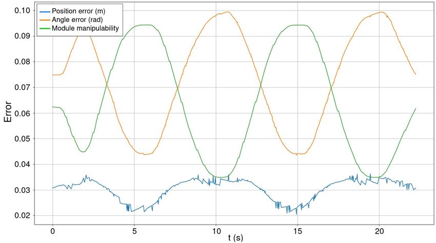
Biomimetics 2023, 8, 11                                                                                            4 of 19

                          in real-world scenarios. With the large advances in technology, these systems overcame this
                          problem and nowadays legged robots are available for real world applications. As a result
                          of this, robots such as ANYmal [18], StarlETH [19], or Spot [20] have appeared and show
                          great performance when walking and running on rough terrain and obstacles. Usually
                          having three DOFs per leg, they use powerful direct driven motors to have a quick response
                          to contingencies. Robots like BigDog [21] or LAURON V [22] increase the number of DOF
                          to four to improve maneuverability, terrain adaptability, and stability.
                                Many types of climbing robots are found in the literature. In [23], the authors present a
                          continuous locomotive motion with a high climbing speed by adopting a series chain on two
                          tracked wheels on which 24 suction pads are installed. Similarly, in [24], a robot is proposed
                          to climb pillars and vertical tubes using wheels that squeeze the inside, that is, the circular
                          or near circular cross section. The OmniClimbers robot [25] uses omnidirectional wheels
                          of robotic platforms [26] to inspect flat and convex human-made ferromagnetic structures
                          using magnets. In [27], the authors present a propeller-type climbing robot for industrial
                          vessel inspection that uses two coaxial upturned propellers (turning in opposite directions
                          to cancel the drag moments) mounted on a mobile robot with four standard wheels.
                                The use of legs for climbing involves introducing some variations with respect to
                          walking robots. That is, it is not enough to add an adhesive system to the tip of the legs,
                          but the kinematics and arrangement of the legs change. Among other things, the body
                          should be kept close to the surface to reduce the stress on the gripping points. Robot
                          SCALER [28] is a quadrupedal robot with four DOF per leg that demonstrates climbing
                          on bouldering walls, overhangs, ceilings and trotting on the ground, while it is unable to
                          climb flat surfaces due to the gripping system. Its legs are practically located in a plane
                          to reduce the risk of overturning. It presents a body posture actuator that improves the
                          robot flexibility and velocity. Robots such as Lemmur IIb [29] or REST [30] are capable
                          of climbing walls of any inclination, while having complications in changing planes and
                          climbing flat areas. The main problem of many climbing robots is to change from one plane
                          to another due to mechanical design, limiting their use in a large number of applications.
                          Rvc robot [31] includes a new DOF in the body to improve the change of plane without
                          success when the planes are far away from each other. In [32], the authors present the
                          quadruped climbing robot Magneto, which has three joints per leg and is able to squeeze
                          through 23 cm gaps.
                                On the other hand, modular robots generally provide more versatility than conven-
                          tional ones. They are reconfigurable and faster to build, maintain, and substitute. However,
                          their adaptability to different applications adds control complexity due to the necessity of
                          generalization. As the number of modules increases, the complexity of many of the com-
                          putational tasks explodes [13]. Roombots is a set of robotic modules that have rotational
                          degrees of freedom for locomotion, as well as active connection mechanisms for runtime
                          reconfiguration [33]. Modules coordination is performed by neural networks CPGs (central
                          pattern generators) that produce coordinated patterns of rhythmic activity without any
                          rhythmic inputs from sensory feedback or from higher control centers [34].
                                The use of modular legs for robots is a good option for those machines whose appli-
                          cation may vary according to the needs. These systems try to imitate nature, which has
                          developed an extraordinary robustness through redundancy and fast adaptation. Walking-
                          Bot [35] is a modular interactive legged robot whose configuration is dynamically detected.
                          It demonstrates behavior with different arrangements, such as quadruped or hexapod
                          configurations. Similarly, ROMHEX [17], which is the previous non-modular version of
                          ROMERIN, demonstrates robustness against loss of several legs, as well as optimizing the
                          position of the legs according to the walking procedure. Desai et al. introduce in [36] an
                          interactive design of a walking robot and an automatic design optimization, while keeping
                          the control of body position. In the same way, Megaro et al. presents an interactive design
                          with the same objective of controlling body pose [37] for different arrangements. In search
                          of robustness through redundancy and fast adaptation of the nature, in [38] the authors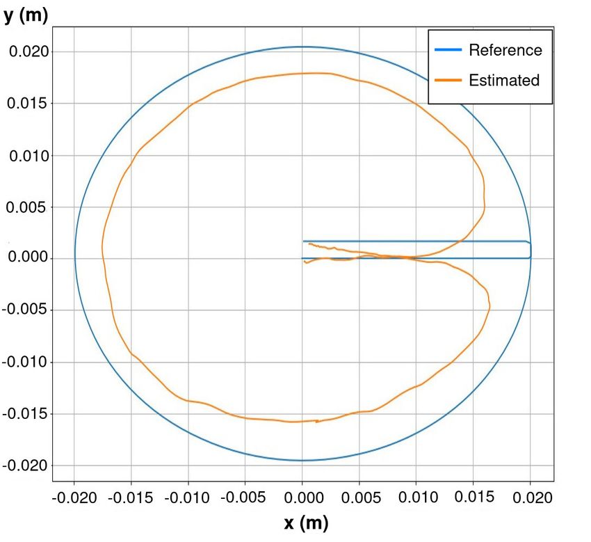
Biomimetics 2023, 8, 11                                                                                              5 of 19

                          present how a modular robotic leg must be designed to tackle structured environments.
                          Similarly, in [36,39] the basic ideas to create legs of a modular robot are presented.
                                The application in which legged climbing robots are used is directly related to the
                          adhesion system. Adhesion by magnetic or electromagnetic force is a common system
                          and is used for inspection, maintenance, and construction work in environments with
                          ferromagnetic materials [3,40]. On the contrary, mechanical adhesion based on grippers
                          is less commonly used due to the environments of destination. Among others, ROMA
                          I [41] and LIBRA [42] use this type of adhesion. On the other hand, for environments
                          such as architectural infrastructures, pneumatic adhesion is the most attractive due to its
                          versatility. Within this group there are those that use passive suction cups [43,44], vacuum
                          chambers [45], and suction by means of vortex generation [46]. Lastly, new adhesion
                          mechanisms have emerged, such as bio-inspired gripping systems, whose main target
                          environments are nature environments.
                                In this paper, we propose a L&C robotic organism that gathers the advantages of
                          many of the most promising ideas. Having a modular design, the number of applications
                          increases considerably against those that are custom-made robots. Accompanying this goal,
                          long legs with a large number of DOFs are used to be able to act in large environments.
                          The adhesion system is based on a turbine that generates a lot of flow. It was selected
                          because of its compactness, versatility, simplicity, adaptability, and suitability for variable
                          environments [47].

                          3. Climbing-and-Legged Robotic Organism
                               To clarify the architecture presented, in this section we describe the modules that we
                          propose for the L&C organism, as well as the main features and requirements that the body
                          of the organism has to complete. The organism is made up of custom modules and is used
                          to test the architecture and validate its behavior.

                          3.1. Description of the Leg Module
                                Based on the idea of reducing complexity, modularizing and releasing workload
                          from the CC, we propose a 7 DOF robotic module [16], which serves as a tool of a whole
                          organism to walk and climb (Figure 2). Having more than 6 DOF allows the module
                          to select the most suitable and safer configuration, optimizing the torque that appears
                          at critical joints. The module is made up of seven servomotors, where the first one is
                          considered a state variable and serves to facilitate the change of plane. Motors are grouped
                          into three clusters, the shoulder (joints 0, 1 and 2), the elbow (joint 3), and the wrist (joints
                          4, 5 and 6). The axes of the last three joints (wrist) are arranged concurrently, with the last
                          two axes in a differential configuration. As a result of that, similarly to what happens in
                          most of the industrial robots, the last three axes intersect at the same point (called wrist
                          point) in such a way that whenever the gripping system is attached to a surface, the wrist
                          point stays static. Contrary to ball joints, the concurrent approach of the wrist allows the
                          module to focus its suction cup against the surface of contact during the swing phase of
                          the walking pattern, that is, this configuration allows orienting the plane and the rotation
                          of the suction cup to place it in the optimal gripping conditions. During the stance phase,
                          the wrist motors are turned off to allow a free position of the suction cup in such a way
                          that the wrist behaves as a ball joint.
                                Due to the morphology of the wrist, the motion of the last two motors does not
                          correspond directly with the motion of the joints. The positive movement of the fifth joint
                          is achieved with the coordinated movement in the opposite direction of motors 5 and 6,
                          rotating motor 5 in the positive direction. On the contrary, the positive movement of the
                          sixth joint is achieved with the coordinated movement and with the same direction of both
                          motors, rotating both in the negative direction.
                                Each module (Figure 2) has its own battery, located in the fourth link (between joints 3
                          and 4). The control of the servomotors is carried out by the microcontroller (MCU) ESP32,
                          located in the electronic board at the third link (between joints 2 and 3). This board sends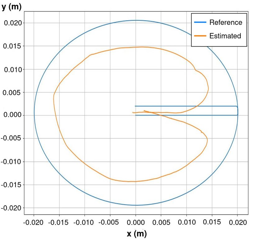
Biomimetics 2023, 8, 11                                                                                        6 of 19

                          and receives information from the servomotors, which have a built-in microcontroller that
                          allows position and velocity control among others. Dynamixel servomotors communicate
                          via half-duplex UART (TTL daisy chained bus). In this scheme, each motor has a unique ID
                          that allows sending and receiving one-to-one commands through the same shared channel.
                          This greatly simplifies wiring and control. The MCU of the board is also able to control
                          the end-effector tool, that is, the suction cup with a turbine that allows the vacuum to be
                          generated. This tool has a pressure and temperature sensor as well as three laser distance
                          transducers that are used to facilitate the alignment of the suction cup with a surface.
                          With the feedback from the pressure sensor, it is immediately possible to determine the
                          gripping force achieved by the suction cup, whose design, efficiency, and performance are
                          described in more detail in [47]. The weight and length of the entire module is 1.94 kg and
                          0.86 m, respectively.

                          Figure 2. Robotic leg module.

                               Each module is capable of communicating through multiple means, wireless (Blue-
                          tooth -BT-, and WiFi) and wired (CAN bus) with the same protocol. For convenience,
                          and being indifferent to the media by which the messages arrive, currently the commu-
                          nication between the modules and the CC is done via WiFi using UDP (User Datagram
                          Protocol) messages. Communication through BT is used to configure parameters or to
                          obtain operating logs.
                               The types of messages that can be sent or received are shown in Table 1. Simplifying,
                          the MCU sends the status of the module, whereas the CC sends the commands to be
                          executed. The modules are programmed in such a way that when there is a connection to a
                          master device (the CC), they send information about their status at a rate of 30 Hz (main
                          motors variables, suction cup pressure and distance sensors, battery voltage and current
                          consumption). To know that a master is connected, it emits a periodic signal to all modules
                          of the organism. This type of message is known as a heartbeat.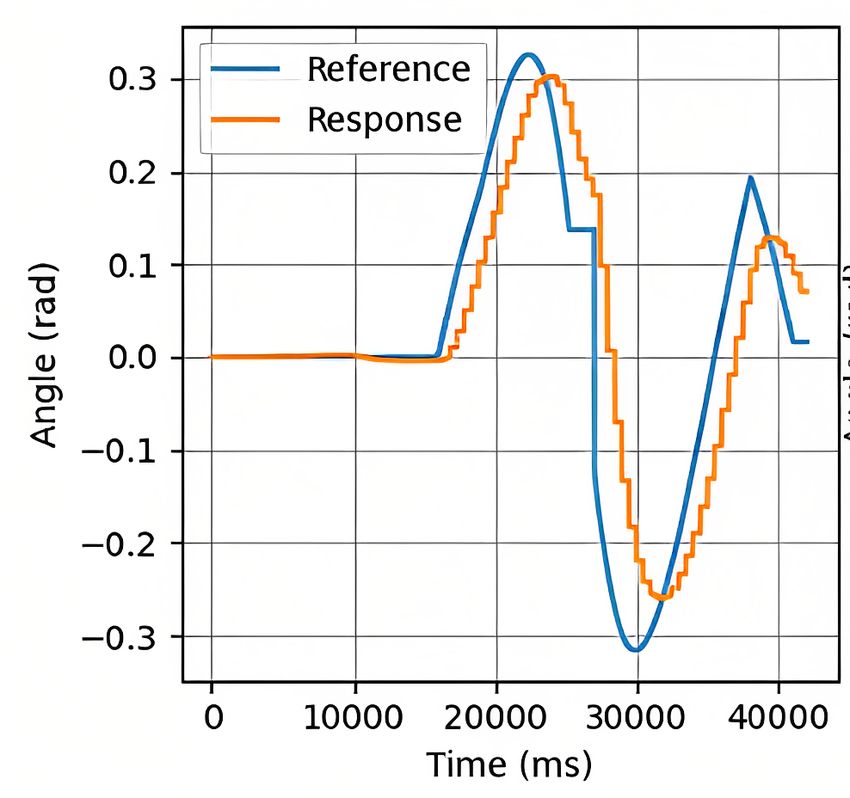
Biomimetics 2023, 8, 11                                                                                              7 of 19

                          Table 1. Main messages between devices.

                           Command                     Data                                              Direction
                                                       Id, position, velocity, intensity, temperature,
                           Motor info
                                                       voltage, status
                           Module info                 Name, network info                                MCU → CC
                           Suction cup info            Pressure, temperature, three distance values
                           Analog info                 Battery voltage, current
                           Motor command               Id, position, velocity, torque (ON/OFF), reboot
                           Get module info             None
                                                                                                         CC → MCU
                           Suction cup command         Suction cup power (%)
                           Master Request              None

                          3.2. Description of the Organism Body
                               In this work, we present the concept of a L&C organism by means of a set of robots.
                          The robotic organism itself does not have a predefined structure. The designer is responsible
                          for ensuring an appropriate arrangement of modules to achieve the desired objectives for
                          a given task. As in the animal world, the unifying element where the legs are attached is
                          called the body, and it should provide the following components:
                          •    A CC: the brain of the organism, responsible for coordination of the robot modules
                               and control of the organism as a whole.
                          •    Reliable physical sockets where to attach the modules.
                          •    A wireless router: modules are able to communicate in a variety of ways. However,
                               for simplicity, the body currently generates its own Wi-Fi (802.11n) to which the
                               different modules connect. Therefore, there is a specific local network for the whole
                               robot organism.
                          •    A RGBd camera: main sensor of the robot to perceive the world.
                          •    An accelerometer: mainly used to determine where the gravity vector points.
                               The body with which we currently validate the concept of the organism and the control
                          strategies is made up of two aluminum plates where the previously detailed components
                          are mounted (Figure 3). First of all, we include a “Jetson Xavier NX Developer Kit”, 8 GB,
                          CPU of 6-core NVIDIA Carmel ARM, 384 NVIDIA CUDA cores, and 48 Tensor cores, as CC.
                          Its small size helps to reduce the body volume. Both aluminum plates are custom made
                          to house four modules, one at each corner of a rectangle with an angle of 45◦ . The Vonets
                          VAR11N mini router and bridge is used to generate the local WiFi, which allows up to
                          20 devices to be connected. Moreover, we have included the “Depth Camera D435i” of
                          RealSense to perceive the environment, which includes the Bosch BMI055 IMU that is
                          used to determine the gravity direction. It is mounted on a pantilt system moved by
                          two Dynamixel motors “XL330-M2888-T”. The control of them is carried out by the CC,
                          which makes use of a “U2D2”, a small size USB communication converter that allows us to
                          control and operate Dynamixel motors with a computer. In addition, a DC-DC converter is
                          installed to supply the pantilt system. Finally, a battery is housed under the bottom plate to
                          supply the CC and the DC-DC converter.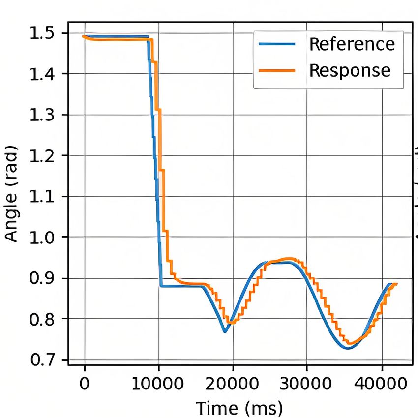
Biomimetics 2023, 8, 11                                                                                           8 of 19

                          Figure 3. Constructed body for a 4-legged robotic organism.

                          4. Digital Twin
                                The development of reliable simulation systems is crucial; therefore, there is a high
                          interest in digital twins. Robot platforms have a high cost due to their materials, sensors,
                          and actuators. A simulation environment can avoid system damage while testing algo-
                          rithms, reducing maintenance and testing time, wasted material, and costs. Furthermore,
                          it is possible to vary the environmental conditions to perform tests in different situations.
                          In general, a reliable virtual model of the system is required when working on large projects.
                          Due to the simulation of complex systems, the testing time is considerably reduced, and in
                          our case, it is possible to test the behavior of organisms with different arrangements and
                          number of modules.
                                A digital twin refers to the virtual model of any physical entity, both of which are
                          interconnected and exchange data in real time [48]. Through its use, we can detect malfunc-
                          tions in the real robot when the same command is sent to both and the behavior is different.
                          For instance, it may be used to check that actuators have enough torque capacities to comply
                          with the task. In this work, we use the Gazebo simulator to create the digital twin of the
                          ROMERIN organism in two modalities: (a) as a simulated and variable organism for testing
                          of algorithms and (b) a digital mirror of the physical robotic organism to check malfunctions
                          (Video available at https://youtu.be/5-jJpLtUR-I, accessed on 24 December 2022).
                                Both modalities have the same structure (Figure 4) and change the way they com-
                          municate with the CC. First of all, the 3D models of a module components are designed,
                          creating a model per set of components that are connected to another set by a joint, that
                          is, for an articulated chain each model represents physically each link. Later, those 3D
                          models are connected within a descriptive file named module model, which may be placed as
                          many times as desired, accompanied by a plugin that specifies the behavior of the module
                          (called module plugin). Each module model has an intrinsic definition of the kinematics
                          and dynamics of a single module, as well as all its components and features. The plugin
                          defines a behavior similar to that of the real modules. This is, as specified in Table 1, it
                          periodically sends messages about the motors, suction cup, and analog information. In the
                          same way, it receives the motor and suction cup commands to be executed and act in the
                          simulated environment.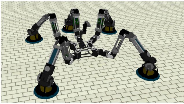
Biomimetics 2023, 8, 11                                                                                         9 of 19

                          Figure 4. Structure of the digital twin of a robotic organism.

                               Similarly, the 3D models of the body components are encapsulated within the body
                          model, whose body plugin defines its behavior, that is, it specifies the performance of the
                          battery, IMU, camera, and pantilt.

                          5. MoCLORA Architecture
                               In the literature, it is possible to find references and some information concerning
                          control architectures for legged robots. For example, Free Gait [49] is designed to control
                          whole-body motions for quadrupedals and is applied to ANYmal and StarlETH robots.
                          Another interesting example is OSCAR [50], a control scheme able to deal with the self-
                          organization, self-reconfiguration, and self-healing of the hexapod robot OSCAR [51].
                          Particular mention should be made of Lauron’s architecture [22], a behavior-based control
                          system. In all these cases, the number and arrangement of their components is previously
                          defined, and it cannot be changed, limiting in this way the range of applications and
                          target environments.
                               The modular Climbing-and-Legged Robotic Organism Architecture arises from the
                          necessity of body position and velocity control of the previously detailed organisms. Mo-
                          CLORA is implemented in C++ and uses ROS2 communication tools to share information
                          between architecture components and devices. It is designed for a general robotic organism
                          composed of leg-shaped robots. The architecture (Figure 5) is focused on the body position
                          and velocity control, in order to imitate the animal world, where individuals care about the
                          body movement, without thinking in a single leg control. The proposed architecture serves
                          as the basis for the control of L&C robots with any morphology, and more components
                          could be included in the general presented framework to improve the performance of
                          the organisms.
                               In the lower part of Figure 5, N physical modules are available. They have the
                          MCU where the firmware is managing, among other tasks, the set of joints. Similarly,
                          the simulation environment (which may be integrated within the CC or externally) includes
                          the world description where the robotic organism is described as indicated in Section 4.
                          The Module Plugin is a virtual realization of the firmware of a physical module. That is, it
                          implements the same interface as the physical modules, so that the control of a simulated
                          or virtual module is exactly the same.
                               The CC is the core of the control architecture and is divided into three layers: HAL,
                          Executive Level, and Scheduler.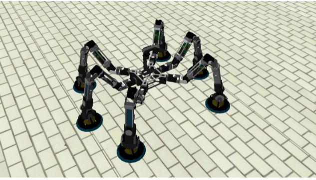
Biomimetics 2023, 8, 11                                                                                                  10 of 19

                          Figure 5. MoCLORA architecture. Rounded rectangles represent hardware devices, while dashed
                          ones represent architecture levels. The dark gray boxes represent C++ objects. Parallelograms are
                          configuration files. The blue containers are ROS2 nodes that use the objects to execute a routine. Gray
                          lines represent inter-device communication, blue ones ROS2 topics for messages exchange (from
                          publisher to subscriber), and dashed ones represent the use of a resource.

                          5.1. HAL
                                The HAL, Hardware Abstraction Layer [52], isolates the modules from the controllers
                          of the modules, that is, the abstraction layers provide a tool to hide complexity when
                          systems become too difficult to efficiently work with. The module controllers send messages
                          to the corresponding system and receive the relevant information from them, in such a
                          way that the controller does not know whether it is moving a real module or a dummy
                          module. To do so, its only component, the Module Communicator, routes the information to
                          transfer. In summary, the HAL level produces the result in such a way that higher levels do
                          not need to take into account if messages are sent to modules of the robotic organism or
                          modules of the digital twin.
                                Messages could arrive from a higher level, in which case they specify a command
                          to be performed by a module, through ROS2 topics with the topic identifier /module-
                          Name/controlToModule. These messages are redirected to the appropriate module based on
                          its IP address and port. In the opposite way, messages may also arrive from a module via
                          WiFi, in which case they specify its status. They are redirected through ROS2 topics with
                          the topic identifier /moduleName/moduleToControl.
Biomimetics 2023, 8, 11 11 of 19
5.2. Executive Level
The Executive Level contains the components that control the modules at a higher
level. It is composed of N Controller Nodes (ROS2 nodes), created dynamically according
to the configuration of the organism. Each one contains a Module Controller, which is
responsible for computing the configuration of the modules, given a goal position of the
body. It includes the Module object, which directly controls the components of a module,
that is, actuators, sensors, and suction cup, as well as the forward and inverse kinematics
of a module (FK and IK respectively). It also implements the management of module
trajectories for both linear TCP (Tool Center Point) trajectories and time-optimal joint
trajectories. In this case, the TCP is defined in the suction cup frame (as shown in Figure 6).
In addition, it defines and receives the information shared with the modules. Due to the
configuration of the wrist, where the last two motors move the last two joints together,
the Module object performs the conversion between the positions and velocities of the two
motors and the positions and velocities of the last two joints.
Figure 6. Organism frames.
Thus, the Module Controller uses the tools provided by the Module object to control
it according to the requirements of the body. Module Controller reads from the Organism
Configuration, which establishes the number of available modules, their name, position
with respect to the center of the body, IP address and port, and body details (maximum
allowed speed, weight, and inertial data). On the other hand, the Module object reads from
the Module Configuration, which details the kinematic and dynamic parameters of a module,
its joints limits, the maximum velocity and acceleration of the TCP, the inverse kinematic
calculation parameters, and the conversion parameters between normalized joints and
Dynamixel motors.
Each Controller Node sends the associated module status (called local status) to the
higher level for its treatment through the topic /moduleName/status:Biomimetics 2023, 8, 11 12 of 19
Local status:
Name
ID
TCP position
Module center of gravity
Estimated body position
Module status:
- Battery level
- 7 values of motor status
- Suction cup power (%)
- Suction cup attachment reliability
- Module movement status
Meanwhile, it receives the following commands to be executed:
Module command:
Body position target
Swing/stance phase
- Target position of the swing phase
5.3. Scheduler
The higher level, called Scheduler, is responsible for generating a trajectory based on
the user’s commands and consequently deciding the most appropriate sequence of body
movements. In more detail, the Trajectory Generator Node generates a speed profile as a
consequence of the command received from the user. Given this profile, the State Manager
Node sends commands to the lower level nodes. Internally, the State Manager calculates
the desired body position to comply with the path, the combined position based on the
estimation of the modules (obtained through the FK), the center of gravity of the entire
robotic organism, the swing turn, and the next position where a module should step. It is
important to point out that at all times the State Manager takes into account the static and
gripping stability of the commanded positions of the robot organism based on the modules
and body positions, direction of gravity, and reaction forces computed in the suction cups.
6. Types of Movements
In the following, some clarifications are made regarding the different movement modes
that can be carried out by the modules during both swing and stance phases. To understand
them, Figure 6 shows the reference frames that we use in the implementation.
6.1. Module Movement in Joint Space
Seven being the number of DOF of the robot, a joint path is defined by q(t) ∈ R7 . This
type of movement is used when a module is not in contact with a surface, that is, it is a
non-support module (during swing phase). In this case, a vector of joints position, velocity,
and acceleration is generated to follow a trajectory. This trajectory might be specified
entirely or created from waypoints. The implementation is found in the Module object,
where the duration of the motion is calculated based on the current state of the joints, their
desired state, and maximum joint velocity and acceleration defined in Module Configuration.
6.2. Module Movement in Cartesian Space
Non-support modules joints can be as well controlled with motion commands in the
Cartesian space R3 × SO(3). In this case, the position, velocity, and acceleration of the TCP
are generated in order to follow a trajectory (SC frame). Features are similar to the previous
motion, but, in this case, the maximum TCP velocity and acceleration are defined. The IK
solver (track-IK [53]) is implemented in the Module object, which is a concurrent inverse
Jacobian and non-linear optimization solver. Due to the redundancy of the problem, the first
joint is considered fixed and given when solving the IK-problem; that is, the kinematicsBiomimetics 2023, 8, 11 13 of 19
is calculated for the last six joints and the first one is only used if the IK-problem has no
solution for the given target.
6.3. Body Movement in Cartesian Space
This motion determines the position and velocity of the body in the Cartesian space
R3 × SO(3), by means of the definition of a point as an interesting point. The desired body
position is followed with the help of the support modules (those that are in stance phase).
There are two options, the first one is using the leg motions in Cartesian space, where the
desired position, velocity, and acceleration is obtained for the TCP frame according to the
base trajectory. The second option neglects the wrist joints, and in this way, the desired
position, velocity and acceleration are calculated respecting the wrist frame. To do so,
geometric methods are used to calculate the required values of the first joints of the chain.
Due to the hyperstaticity of the organism, the system is over-constraint, and small
errors in the estimation of the TCP position (due to the mechanical gaps and mismatches)
lead to motors overload. For this reason, during the trajectory execution, the wrist motors
torque transmission deactivated and the wrist remains in free movement, thus avoiding
the appearance of torques, and allowing the free orientation against the coupling surface.
7. Results
MoCLORA has been tested with both the digital twin and the real robot. First, simple
body movements (Videos available at https://youtu.be/w02W8tUM64E and https://
youtu.be/9Q0KD2YcXns, accessed on 24 December 2022), and secondly, body trajectories
such as circles or squares have been commanded (Videos available at https://youtu.
be/myqL09stIFk and https://youtu.be/6PVj6xO7kCk, accessed on 24 December 2022).
The performance of the organism for the proposed body is tested in Section 3. Figure 7
shows a sequence of a circular motion performed in both the simulated and physical robotic
system. The trajectory is generated by the Trajectory Generator node of the Scheduler layer,
which sends a velocity profile to the State Manager Node.
Figure 7. Results for the digital twin (up) and physical (down) organisms while carrying out a
circular trajectory. Pictures 1 show the initial configuration, and the rest show catches of the trajectory.
Squares and circle trajectories have been used for hardware, firmware, and software
infrastructure testing. Figure 8 shows the commanded and estimated body trajectory for
both the digital twin and the physical organism proposed in Section 3. It is observed to have
higher accuracy in the digital twin. This fact is attributed to the looseness of connecting
pieces, which prevents motors from reaching the desired position due to the hyperstaticity
of the system while adhering to the environment. In that figure, estimated values are
obtained through the FK of the legs. Because the initial state of the organism is known,
the body position is straightforwardly computed as
Σ̂ Bi = B Σi0 · i0 Σtcp,t=0 · i0 Σ− 1 B −1
tcp,t=k · Σi0 (1)Biomimetics 2023, 8, 11 14 of 19
where Σ̂ Bi is the position estimation of the body frame by the module i, B Σi0 the transforma-
tion from the body frame to the first joint frame of module i, i0 Σtcp,t=0 its FK in the initial
state, and i0 Σtcp,t=k its FK at time k. Since there is the same number of valid solutions as
legs, currently the estimation shown in Figure 8 is implemented as their average.
(a) (b)
Figure 8. Body commanded and estimated position of both digital twin and physical organism.
(a) Body trajectory of the physical organism. (b) Body trajectory of the digital twin.
The corresponding commanded and achieved joint trajectories for the motors 1 to 3 of
a module are shown in Figure 9 for both cases. As observed in the results, the commanded
joints positions are analogous. As indicated previously, during the control of the body by
means of the support modules, the wrist motors torque transmission is deactivated (only
from a torque point of view, the encoder reading, communication with the motor and other
features is available), and consequently its movement is free, which is why the positions
of those joints are not shown. In Figure 9, it is also possible to observe that the motors’
responses do not receive the reference signal completely. This is deduced from the fact that
the control of each motor is carried out with a PD controller, which prevents the motors
from applying an excessive force when the reference is not reached. This fact would be
common for L&C robots such as ours, which are hyperstatic systems while adhered to the
environment, and due to the looseness of links, the reference would not be reached at any
time without putting the integrity of the robot at risk. For the same reason, the integrative
component is removed from the controller, which would cause the motor to overload.
We have used MoCLORA in different organism configurations for the proposed trajec-
tories (Video available at https://youtu.be/nOxRKEuagnw, accessed on 24 December 2022).
More specifically, the execution of various types of trajectories with the following arrange-
ment of modules has been tested on the simulator (Figure 10 shows these configurations):
• A four-legged organism identical to the physically built body, that is, the legs are
mounted at the corners of a square with an angle of 45◦ (Figure 10a).
• A six-legged organism with the previous body where the new legs are added on the
sides and opposite orientation (Figure 10b).
• A seven-legged organism, adding a leg to the back of the previous organism (Figure 10c).
• A six-legged organism, where the lateral legs are moved far away from the body
(Figure 10d).
• A ten-legged organism. In this case, the body is a large aluminum plate, where five
legs have been added to each plate side (Figure 10e).
• A five-legged organism, where one of the lateral legs of the six-legged organism is
removed (Figure 10f).Biomimetics 2023, 8, 11 15 of 19
(a) (b) (c)
(d) (e) (f)
Figure 9. Digital twin (a–c) and real joints trajectories (d–f) of a single module while performing
a circular movement (trajectory shown on Figure 8). (a) Joint 1 of the digital twin, (b) Joint 2 of
the digital twin, (c) Joint 3 of the digital twin, (d) Joint 1 of the physical organism, (e) Joint 2 of the
physical organism, and (f) Joint 3 of the physical organism.
(a) (b) (c)
(d) (e) (f)
Figure 10. Examples of tested organism arrangements. (a) 4 legs, (b) 6 legs, 1st configuration,
(c) 10 legs, (d) 6 legs, 2nd configuration, (e) 7 legs, and (f) 5 legs.
From the simulation of body trajectories with different arrangements and the study of
their joint trajectories, it is concluded that there is good behavior of the control architecture
for different numbers of modules located in different positions of the body. The imple-
mentation of such arrangements in physical robotic organisms requires the construction
of more modules and the design of new bodies that can house them (including, of course,
the necessary elements proposed in Section 3.2). The only difference with respect to the
control of the quadruped proposed in this article is the redefinition of the Organism Config-
uration component of the control architecture shown in Figure 5, while keeping all other
components intact.
Lastly, Figure 11 shows the angular and distance errors of a module during the circular
trajectory denoted previously. In the same picture, the module manipulability is plotted.
As observed experimentally, the angular and positional error fluctuates in the oppositeBiomimetics 2023, 8, 11 16 of 19
direction to the manipulability. This is, the maximum estimation errors correspond to
the moments when the module is more shrunken or stretched, and the manipulability
decreases, preventing the body from moving comfortably. Manipulability is computed
with the track-IK solver [53] as indicated in (2):
w = cs · det( J · J T )0.5 (2)
where cs is the scalability constant for visualization, and J is the jacobian matrix of the
last six joints of a module. Regarding the angular and positional error with different
arrangements, there is no significant variation with respect to the test carried out with the
4-legged organism. The mean error is about 0.072 ± 0.011 rad and 2.8 ± 0.5 cm.
Figure 11. Module manipulability over the angular and distance error of the estimation that a
module does during a circular trajectory (Figure 8). Manipulability line has been scaled for represent-
ation purposes.
The robot payload increases with the number of modules and varies with the distribu-
tion of the modules. In the case of the developed body, the payload when it is standing,
as shown in the videos, is around 2.4 kg (including the weight of the developed body).
Even though the payload depends on the modules arrangement, it is estimated that each
module is capable of holding 0.6 kg with a distributed load between modules.
8. Conclusions
In this paper, we have presented MoCLORA, a framework centered on the control
of body position and velocity of climbing organisms formed by the composition of legs.
Each leg, or module, is an independent unit that can be used to construct a more complex
structure, such as the said organism. In this way, the disposal of modules may vary
according to the task to carry out. For example, if modules are used to inspect a cooling
tower, the proposed body and legs configuration in Section 3 would suit, whereas if the
task is to carry a load of higher dimensions, a larger and wider body would be needed.
Thanks to the energy sharing of the modules, the organism has around 90 min of
autonomy during operation. In fact, scalability in size of the robot, that is, in the number of
modules, is not a problem due to the modular approach of the system, where each module
has its own battery. The proposed concept has the main advantage that a variable load can
be carried depending on the number of legs, in such a way that payload is distributed as
evenly as possible on the legs.Biomimetics 2023, 8, 11 17 of 19
From a control point of view, scalability in the number of modules increases the
computational cost. The control loop of each module is carried out at 800 Hz in the
organism CC for a quadruped arrangement, whereas the internal control loop of each
module is 30 Hz, as indicated in Section 3. The more modules there are in the organism,
the worse the control rate will be. The limit is set when the control loop rate is 60 Hz
(double of the module control loop), but this value is far away from reality even though
controlling a ten-legged robot with the proposed CC.
We have detailed the features of modules and their digital twins, their communication
protocols, devices, and structure, as well as the adhesion component between modules,
that is, the body. So far, we have used MoCLORA on the physical organism and its digital
twin, as well as on other organisms that present various configurations. We have realized
a tool made up of modular components, both hardware and software, achieving a rapid
fine-tuning of the organism by adding or removing modules and specifying their location.
These facts lead the proposed system to be used in a wide range of applications and in a
large number of environments.
MoCLORA serves as the base architecture for the control of L&C robots with any
morphology, in such a way that more components could be included to improve the
capabilities of the organism, enabling more complex controls. For example, an exception-
based agent is required for providing the robot with walking and climbing ability, as well
as other safety procedures, robustness and fault-tolerance techniques. As an example
of biomimicry, it is crucial to include a locomotion agent within the Scheduler layer that
imitates the insect behavior. A path planning that optimizes the safety of the organism and
reduces consumption is also required in a larger architecture.
Author Contributions: Conceptualization, C.P., M.H. and E.G.; methodology, C.P., M.H. and E.G.;
software, C.P.; validation, C.P.; formal analysis, C.P. and M.H.; investigation, C.P., M.H. and E.G.;
resources, C.P., M.H., E.G. and A.B.; data curation, C.P.; writing—original draft preparation, C.P.;
writing—review and editing, M.H., E.G. and A.B.; visualization, C.P.; supervision, M.H. and E.G.;
project administration, C.P., M.H., E.G. and A.B.; funding acquisition, M.H., E.G. and A.B. All authors
have read and agreed to the published version of the manuscript.
Funding: The research leading to these results has received funding from RoboCity2030-DIH-CM,
Madrid Robotics Digital Innovation Hub, S2018/NMT-4331, funded by “Programas de Actividades
I+D en la Comunidad de Madrid” and co-financed by Structural Funds of the EU. The project in
which this research is being developed was initially funded by the Spanish National Plan for Scientific
and Technical Research and Innovation, DPI2017-85738-R.
Institutional Review Board Statement: Not applicable.
Informed Consent Statement: Not applicable.
Data Availability Statement: Not applicable.
Acknowledgments: The authors would like to thank Pablo Quesada for his support in the acquisition
of materials and maintenance of the laboratory.
Conflicts of Interest: The authors declare no conflict of interest.
References
1. Katz, D.; Kenney, J.; Brock, O. How can robots succeed in unstructured environments. In Proceedings of the In Workshop on Robot
Manipulation: Intelligence in Human Environments at Robotics: Science and Systems, Zurich, Switzerland, 25–28 June 2008.
2. Hernando, M.; Brunete, A.; Gambao, E. ROMERIN: A Modular Climber Robot for Infrastructure Inspection. IFAC-PapersOnLine
2019, 52, 424–429. [CrossRef]
3. Iida, F. Autonomous Robots: From Biological Inspiration to Implementation and Control. Artif. Life 2007, 13, 419–421. [CrossRef]
4. Tan, K.C.; Wang, L.; Lee, T.H.; Vadakkepat, P. Evolvable Hardware in Evolutionary Robotics. In World Scientific Series in Robotics
and Intelligent Systems; World Scientific: Singapore, 2006; pp. 33–62. [CrossRef]
5. Machado, J.T.; Silva, M.F. An overview of legged robots. In Proceedings of the International Symposium on Mathematical
Methods in Engineering, Ankara, Turkey, 27–29 April 2006; pp. 1–40.
6. Büschges, A.; Schmidt, J. Neuronal control of walking: Studies on insects. e-Neuroforum 2015, 21, 105–112. [CrossRef]
7. Ding, X.; Wang, Z.; Rovetta, A.; Zhu, J. Locomotion analysis of hexapod robot. Climbing Walk. Robot. 2010, 30, 291–310.Biomimetics 2023, 8, 11 18 of 19
8. Mahkam, N.; Özcan, O. Gait and locomotion analysis of a soft-hybrid multi-legged modular miniature robot. Bioinspir. Biomim.
2021, 16, 066009. [CrossRef]
9. Li, H.; Zhu, G.; Arena, P.; Yu, M.; Yu, Z.; Patanè, L. Bio-Inspired Locomotion Control of Gecko-Mimic Robot: From Biological
Observation to Robot Control. IEEE Instrum. Meas. Mag. 2022, 25, 28–35. [CrossRef]
10. Wu, Q.; Liu, C.; Zhang, J.; Chen, Q. Survey of locomotion control of legged robots inspired by biological concept. Sci. China Ser. F
Inf. Sci. 2009, 52, 1715–1729. [CrossRef]
11. Shao, D.; Wang, Z.; Ji, A.; Dai, Z.; Manoonpong, P. A gecko-inspired robot with CPG-based neural control for locomotion and
body height adaptation. Bioinspir. Biomim. 2022, 17, 036008. [CrossRef]
12. Lin, C.Y.; Hu, T.C. Development and locomotion control of a horizontal ledge-climbing robot. In Proceedings of the 2021 7th
International Conference on Control, Automation and Robotics (ICCAR), Singapore, 23–26 April 2021; pp. 60–64.
13. Yim, M.; Zhang, Y.; Duff, D. Modular robots. IEEE Spectr. 2002, 39, 30–34. [CrossRef]
14. Gilpin, K.; Rus, D. Modular Robot Systems. IEEE Robot. Autom. Mag. 2010, 17, 38–55. [CrossRef]
15. Humza, R.; Scholz, O.; Mokhtar, M.; Timmis, J.; Tyrrell, A. Towards Energy Homeostasis in an Autonomous Self-Reconfigurable
Modular Robotic Organism. In Proceedings of the 2009 Computation World: Future Computing, Service Computation, Cognitive,
Adaptive, Content, Patterns, Athens, Greece, 15–20 November 2009. [CrossRef]
16. Hernando, M.; Gambao, E.; Prados, C.; Brito, D.; Brunete, A. ROMERIN: A new concept of a modular autonomous climbing
robot. Int. J. Adv. Robot. Syst. 2022, 19, 17298806221123416. [CrossRef]
17. Hernando, M.; Alonso, M.; Prados, C.; Gambao, E. Behavior-Based Control Architecture for Legged-and-Climber Robots.
Appl. Sci. 2021, 11, 9547. [CrossRef]
18. Hutter, M.; Gehring, C.; Jud, D.; Lauber, A.; Bellicoso, C.D.; Tsounis, V.; Hwangbo, J.; Bodie, K.; Fankhauser, P.; Bloesch, M.; et al.
ANYmal—A highly mobile and dynamic quadrupedal robot. In Proceedings of the 2016 IEEE/RSJ International Conference on
Intelligent Robots and Systems (IROS), Daejeon, Republic of Korea, 9–14 October 2016. [CrossRef]
19. Hutter, M.; Gehring, C.; Bloesch, M.; Hoepflinger, M.A.; Remy, C.D.; Siegwart, R. StarlETH: A compliant quadrupedal robot
for fast, efficient, and versatile locomotion. In Adaptive Mobile Robotics; World Scientific: Singapore, 2012; pp. 483–490. ._0062.
[CrossRef]
20. Spot—The Agile Mobile Robot. Boston Dynamics. Available online: https://www.bostondynamics.com/products/spot
(accessed on 8 February 2022).
21. Raibert, M.; Blankespoor, K.; Nelson, G.; Playter, R. BigDog, the Rough-Terrain Quadruped Robot. IFAC Proc. Vol. 2008,
41, 10822–10825. [CrossRef]
22. Roennau, A.; Heppner, G.; Nowicki, M.; Dillmann, R. LAURON V: A versatile six-legged walking robot with advanced
maneuverability. In Proceedings of the 2014 IEEE/ASME International Conference on Advanced Intelligent Mechatronics,
Besançon, France, 8–11 July 2014. [CrossRef]
23. Kim, H.; Kim, D.; Yang, H.; Lee, K.; Seo, K.; Chang, D.; Kim, J. Development of a wall-climbing robot using a tracked wheel
mechanism. J. Mech. Sci. Technol. 2008, 22, 1490–1498. [CrossRef]
24. Baghani, A.; Ahmadabadi, M.; Harati, A. Kinematics Modeling of a Wheel-Based Pole Climbing Robot (UT-PCR). In Proceedings
of the 2005 IEEE International Conference on Robotics and Automation, Barcelona, Spain, 18–22 April 2005. [CrossRef]
25. Tavakoli, M.; Viegas, C.; Marques, L.; Pires, J.N.; de Almeida, A.T. OmniClimbers: Omni-directional magnetic wheeled climbing
robots for inspection of ferromagnetic structures. Robot. Auton. Syst. 2013, 61, 997–1007. [CrossRef]
26. Prados Sesmero, C.; Buonocore, L.R.; Castro, M.D. Omnidirectional Robotic Platform for Surveillance of Particle Accelerator
Environments with Limited Space Areas. Appl. Sci. 2021, 11, 6631. [CrossRef]
27. Alkalla, M.G.; Fanni, M.A.; Mohamed, A.M.; Hashimoto, S. Tele-operated propeller-type climbing robot for inspection of
petrochemical vessels. Ind. Robot. Int. J. 2017, 44, 166–177. [CrossRef]
28. Tanaka, Y.; Shirai, Y.; Lin, X.; Schperberg, A.; Kato, H.; Swerdlow, A.; Kumagai, N.; Hong, D. Scaler: A tough versatile quadruped
free-climber robot. arXiv 2022, arXiv:2207.01180.
29. Kennedy, B.; Okon, A.; Aghazarian, H.; Badescu, M.; Bao, X.; Bar-Cohen, Y.; Chang, Z.; Dabiri, B.E.; Garrett, M.; Magnone, L.; et al.
Lemur IIb: A robotic system for steep terrain access. Ind. Robot. Int. J. 2006, 33, 265–269. [CrossRef]
30. Grieco, J.; Prieto, M.; Armada, M.; de Santos, P.G. A six-legged climbing robot for high payloads. In Proceedings of the 1998 IEEE
International Conference on Control Applications (Cat. No. 98CH36104), Trieste, Italy, 4 September 1998. [CrossRef]
31. Peters, G.; Pagano, D.; Liu, D.; Waldron, K. A prototype climbing robot for inspection of complex ferrous structures. In Emerging
Trends in Mobile Robotics; World Scientific: Singapore, 2010. [CrossRef]
32. Bandyopadhyay, T.; Steindl, R.; Talbot, F.; Kottege, N.; Dungavell, R.; Wood, B.; Barker, J.; Hoehn, K.; Elfes, A. Magneto: A
Versatile Multi-Limbed Inspection Robot. In Proceedings of the 2018 IEEE/RSJ International Conference on Intelligent Robots
and Systems (IROS), Madrid, Spain, 1–5 October 2018. [CrossRef]
33. Sprowitz, A.; Pouya, S.; Bonardi, S.; Kieboom, J.V.D.; Mockel, R.; Billard, A.; Dillenbourg, P.; Ijspeert, A.J. Roombots: Reconfig-
urable Robots for Adaptive Furniture. IEEE Comput. Intell. Mag. 2010, 5, 20–32. [CrossRef]
34. Spröwitz, A.; Moeckel, R.; Vespignani, M.; Bonardi, S.; Ijspeert, A. Roombots: A hardware perspective on 3D self-reconfiguration
and locomotion with a homogeneous modular robot. Robot. Auton. Syst. 2014, 62, 1016–1033. [CrossRef]Biomimetics 2023, 8, 11 19 of 19
35. Wang, M.; Su, Y.; Liu, H.; Xu, Y. WalkingBot: Modular Interactive Legged Robot with Automated Structure Sensing and Motion
Planning. In Proceedings of the 2020 29th IEEE International Conference on Robot and Human Interactive Communication
(RO-MAN), Naples Italy, 31 August–4 September 2020. [CrossRef]
36. Desai, R.; Li, B.; Yuan, Y.; Coros, S. Interactive co-design of form and function for legged robots using the adjoint method. In
Robotics Transforming the Future; CLAWAR Association Ltd.: High Wycombe, UK, 2018. [CrossRef]
37. Megaro, V.; Thomaszewski, B.; Nitti, M.; Hilliges, O.; Gross, M.; Coros, S. Interactive design of 3D-printable robotic creatures.
ACM Trans. Graph. 2015, 34, 1–9. [CrossRef]
38. Buettner, T.; Wilke, D.; Roennau, A.; Heppner, G.; Dillmann, R. A scalable, modular leg design for multi-legged stair climbing
robots. In Robotics Transforming the Future; CLAWAR Association Ltd.: High Wycombe, UK, 2018. [CrossRef]
39. Buettner, T.; Heppner, G.; Roennau, A.; Dillmann, R. Nimble Limbs—Intelligent attachable legs to create walking robots from
variously shaped objects. In Proceedings of the 2019 IEEE/ASME International Conference on Advanced Intelligent Mechatronics
(AIM), Hong Kong, China, 8–12 July 2019. [CrossRef]
40. Koo, I.M.; Trong, T.D.; Lee, Y.H.; Moon, H.; Koo, J.; Park, S.K.; Choi, H.R. Development of Wall Climbing Robot System by Using
Impeller Type Adhesion Mechanism. J. Intell. Robot. Syst. 2013, 72, 57–72. [CrossRef]
41. Balaguer, C.; Pastor, J.; Giménez, A.; Padrón, V.; Abderrahim, M. ROMA: Multifunctional autonomous self-supported climbing
robot for inspection applications. IFAC Proc. Vol. 1998, 31, 563–568. [CrossRef]
42. Longo, D.; Muscato, G. Adhesion Control for the Alicia3 Climbing Robot. In Climbing and Walking Robots; Springer:
Berlin/Heidelberg, Germany, 2005; pp. 1005–1015. [CrossRef]
43. Yoshida, Y.; Ma, S. Design of a wall-climbing robot with passive suction cups. In Proceedings of the 2010 IEEE International
Conference on Robotics and Biomimetics, Tianjin, China, 14–18 December 2010. [CrossRef]
44. Kawasaki, S.; Kikuchi, K. Development of a small legged wall climbing robot with passive suction cups. In Proceedings of the 3rd
International Conference on Design Engineering and Science, Pilsen, Czech Republic, 31 August–3 September 2014; Volume 2014,
pp. 112–116.
45. Hillenbrand, C.; Schmidt, D.; Berns, K. CROMSCI: Development of a climbing robot with negative pressure adhesion for
inspections. Ind. Robot. Int. J. 2008, 35, 228–237. [CrossRef]
46. Disney. VertiGo–A Wall-Climbing Robot including Ground-Wall Transition. 2015. Available online: https://la.disneyresearch.
com/publication/vertigo/ (accessed on 1 June 2022).
47. Hernando, M.; Gómez, V.; Brunete, A.; Gambao, E. CFD Modelling and Optimization Procedure of an Adhesive System for a
Modular Climbing Robot. Sensors 2021, 21, 1117. [CrossRef]
48. Singh, M.; Fuenmayor, E.; Hinchy, E.; Qiao, Y.; Murray, N.; Devine, D. Digital Twin: Origin to Future. Appl. Syst. Innov. 2021,
4, 36. [CrossRef]
49. Fankhauser, P.; Bellicoso, C.D.; Gehring, C.; Dube, R.; Gawel, A.; Hutter, M. Free Gait—An architecture for the versatile control of
legged robots. In Proceedings of the 2016 IEEE-RAS 16th International Conference on Humanoid Robots (Humanoids), Cancun,
Mexico, 15–17 November 2016. [CrossRef]
50. Maehle, E.; Brockmann, W.; Grosspietsch, K.E.; Auf, A.E.S.; Jakimovski, B.; Krannich, S.; Litza, M.; Maas, R.; Al-Homsy, A.
Application of the Organic Robot Control Architecture ORCA to the Six-Legged Walking Robot OSCAR. In Organic Computing—A
Paradigm Shift for Complex Systems; Springer: Basel, Switzerland, 2011; pp. 517–530. [CrossRef]
51. Jakimovski, B.; Meyer, B.; Maehle, E. Self-reconfiguring hexapod robot OSCAR using organically inspired approaches and
innovative robot leg amputation mechanism. In Proceedings of the International Conference on Automation, Robotics and
Control Systems, ARCS-09, Orlando, FL, USA, 13–16 July 2009.
52. Murray IV, T.J.; Pham, B.N.; Pirjanian, P. Hardware Abstraction Layer for a Robot. US Patent 6,889,118, 20 March 2008.
53. Beeson, P.; Ames, B. TRAC-IK: An open-source library for improved solving of generic inverse kinematics. In Proceedings of the
2015 IEEE-RAS 15th International Conference on Humanoid Robots (Humanoids), Toronto, ON, Canada, 15–17 October 2015.
[CrossRef]
Disclaimer/Publisher’s Note: The statements, opinions and data contained in all publications are solely those of the individual
author(s) and contributor(s) and not of MDPI and/or the editor(s). MDPI and/or the editor(s) disclaim responsibility for any injury to
people or property resulting from any ideas, methods, instructions or products referred to in the content.You can also read