M4-CV Series VAV Box Controllers Installation Guide
←
→
Page content transcription
If your browser does not render page correctly, please read the page content below
M4-CV Series VAV Box Controllers Installation
                                                                        Guide
                                                                                              Part No. 24-10143-01590 Rev. D
                                                                                                                       11.0
                                                                                                                  2022-02-07

Application                                                    To configure CVM controllers to communicate using
                                                               the N2 communications protocol, see Configuring N2
The CV series controllers are designed for variable air        communications (CVM models only).
volume (VAV) box applications.                                 To configure CVM controllers to communicate using
CV series controllers feature 14 preloaded standard            the wireless communications protocol, see Configuring
applications to allow this controller to operate               wireless communications (CVM models only).
standard VAV box equipment with a proven energy-
efficient sequence of operation, without the need for          North American Emissions Compliance
programming. For information on configuring a CV series
controller to use a preloaded application, see Setting a       United States
preloaded application. These controllers are also fully
programmable, using the Controller Configuration Tool          This equipment has been tested and found to comply
(CCT), providing the flexibility to create custom control      with the limits for a Class A digital device pursuant to
sequences.                                                     Part 15 of the FCC Rules. These limits are designed
                                                               to provide reasonable protection against harmful
CV series controllers feature an integral damper actuator,     interference when this equipment is operated in a
a digital Differential Pressure Transmitter (DPT) sensor,      commercial environment. This equipment generates,
and a 32-bit microprocessor. The CVM03050-0P and               uses, and can radiate radio frequency energy and, if not
CVE03050-0P models feature an integral potentiometer           installed and used in accordance with the instruction
to sense actual VAV box damper position. For information       manual, may cause harmful interference to radio
on configuring an application with integrated actuator         communications. Operation of this equipment in a
feedback, refer to the M4-CV Series Actuator Feedback          residential area may cause harmful interference, in which
Application Note (LIT-12013631).                               case the users will be required to correct the interference
CV series controllers also include an integral real-time       at their own expense.
clock, which enables the controllers to monitor and
control schedules, calendars, and trends, and operate
for extended periods of time as stand-alone controllers        Canada
when offline from the Metasys system network. These
controllers connect easily to the wired and wireless           This Class (A) digital apparatus meets all the
network sensors for zone and discharge air temperature         requirements of the Canadian Interference-Causing
sensing. Their small package size facilitates quick            Equipment Regulations.
field installation and efficient use of space without          Cet appareil numérique de la Classe (A) respecte toutes
compromising control performance.                              les exigences du Règlement sur le matériel brouilleur du
                                                               Canada.
Communications protocols
CV series controllers can communicate using multiple           Installation
communication protocols depending on model and
configuration. The CVE controllers communicate using           Observe the following guidelines when installing the
the BACnet/IP communication protocol. CVM controllers          controller:
communicate using the BACnet MS/TP, N2, or wireless            • To minimize vibration and shock damage to the
Zigbee® communications protocols, with the addition              controller, transport the controller in the original
of ZFR183x Pro Wireless Field Bus Routers. Equipment             container.
Controllers in BACnet/IP or BACnet/MSTP communication          • Verify that all parts shipped with the controller.
mode are BACnet network-compliant devices. The
BACnet protocol is a standard for ANSI, ASHRAE, and the        • Do not drop the controller or subject it to physical
International Standards Organization (ISO) for building          shock.
controls.
                                                               Parts included
Controllers running in N2 mode can be used to maintain
or modernize sites with installed legacy Johnson Controls®     • One CVM/CVE controller with removable terminal
controllers. For installation and commissioning support,         blocks (Input/Output, Power, FC, and SA terminal blocks
and tips for efficient and safe replacement, refer               bus are removable)
to the Modernization Guide for Legacy N2 Controllers
(LIT-12012005) and the controller-specific documentation.              Note: The FC terminal block is only available with
For information about mapping N2 Objects in controllers                the CVM model
with switchable communications protocols, refer to the         • One installation instructions sheet
N2 Compatibility Options chapter of the Controller Tool Help   • One self-drilling No. 10 x 25 mm (1 in.) screw
(LIT-12011147).

                                                                                     *241014301590D*
                                                                                               (barcode for factory use only)
                                                                                           M4-CVM03050-0x, M4-CVE03050-0P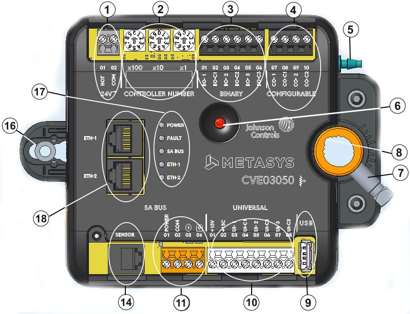
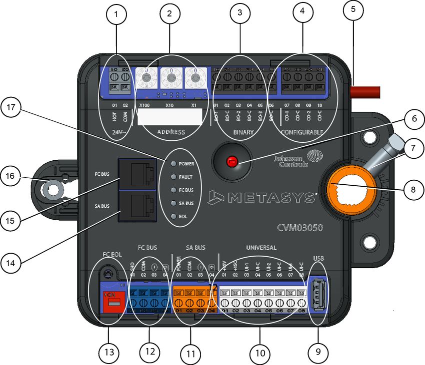
Materials and special tools needed                           Table 1: CVx series physical features
• Small, straight-blade (1/8 in. or 3.2mm) or Phillips #2            Physical features: description and references
  screwdriver for securing wires in the terminal blocks
                                                             1       Supply Power Terminal Block: Gray terminals. See
• 8 mm (5/16 in.) wrench or 10 mm (3/8 in.) 12-point
                                                                     Supply power terminal block.
  socket to tighten the square coupler bolt
• Several shims or washers to mount the CVM/CVE              2       Rotary Switches:
• Power screwdriver, 100 mm (4 in.) extension socket,                CVM: Decimal addressing. See Setting the device
  punch, drill, and 3.5 mm (9/64 in.) drill bits to mount            address on CVM models.
  the controller                                                     CVE: Controller number. See Setting the controller
• Pliers to open and close the damper                                number for CVE models
• Required length of 3.97 mm (5/32 in.) ID pneumatic         3       Binary Output (BO) Terminal Block: Black terminals. See
  tubing and barbed fittings                                         Table 5.

Physical features                                            4       Configurable Outputs (CO) Terminal Block: Black
                                                                     terminals. See Table 5.
The following figures display the physical features of
                                                             5       Dual Port Fitting.
the CVM/CVE controllers, and the accompanying table
provides a description of the physical features and a        6       Manual Override Button. See Mounting.
reference to further information where required.             7       Coupler Bolt

Figure 1: CVM03050 physical features                         8       Controller Coupler. See Mounting.
                                                             9       Universal Serial Bus (USB) 2.0 Host Type A Port
                                                                     Note: The USB feature is not currently supported.
                                                             10      Universal Inputs (UI) Terminal Block: White terminals.
                                                                     See Table 5.
                                                             11      Sensor Actuator (SA) Bus Terminal Block: Orange
                                                                     terminal. See SA Bus terminal block.
                                                             12      Field Controller (FC) Bus Terminal Block: Blue terminal;
                                                             (CVM    may also be used for N2 connections, see FC Bus
                                                             only)   terminal block (or N2 protocol as required) on CVM
                                                                     controllers.
                                                             13      EOL (End-of-Line) Switch. See Setting the End-of-Line
                                                             (CVM    (EOL) switch (CVM models only).
                                                             only)
                                                             14      Sensor (SA Bus) Port: RJ-12 6-Pin Modular Jack. See
                                                                     Sensor (SA Bus) Port.
                                                             15      FC Bus Port: RJ-12 6-Pin Modular Jack. See FC Bus Port
Figure 2: CVE03050 physical features                                 on CVM models.
                                                             (CVM
                                                             only)
                                                             16      Captive Spacer and Screw.
                                                             17      LED Status Indicators. See LED Table.
                                                             18      Ethernet Ports: ETH-1 and ETH-2. See BACnet/IP
                                                                     Ethernet Network Topology for CVE controllers

                                                             Mounting
                                                             Observe the following guidelines when mounting a CVM/
                                                             CVE controller:
                                                             • Ensure that the mounting surface can support the
                                                               controller and any user-supplied enclosure.
                                                             • Mount the controller on a hard, even surface whenever
                                                               possible.
                                                             • Use shims or washers to mount the controller securely
                                                               and evenly on the mounting surface.
                                                             • Mount the controller in an area free of corrosive vapors
                                                               that matches the ambient conditions specified in the
                                                               Technical specifications section.

2      M4-CV Series VAV Box Controllers Installation Guide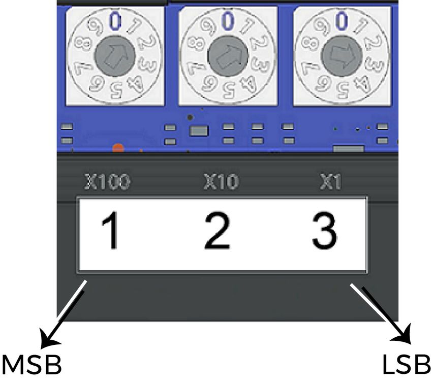
• Provide sufficient space around the controller for cable      3.     Secure the self-drilling No.10 screw through
  and wire connections and adequate ventilation through                the captive spacer (see Figure 1) with a power
  the controller (at least 50 mm [2 in.] on the top, bottom,           screwdriver and 100mm (4in.) extension socket.
  sides, and front of the controllers).                                Otherwise, use a punch to mark the position of
• Do not mount the controller in areas where                           the shoulder washer, and then drill a hole into the
  electromagnetic emissions from other devices or wiring               VAV box using a 3.5mm (9/64in.) drill bit. Insert the
  can interfere with controller communication.                         mounting screw and tighten against the spacer.
• Avoid mounting the controller on surfaces with                            Important: Do not overtighten the screw, or
  excessive vibration.                                                      the threads may strip. If mounting to the VAV
     Important: When the air supply to the VAV box is                       box, make sure the screws do not interfere with
     below 10°C (50°F), make sure that any condensation                     damper blade movement.
     on the VAV box, particularly on the damper shaft,          4.     Locate the damper position using the typical
     does not enter the controller electronics. Mount                  marking on the end of the damper shaft as shown in
     the controller vertically above the damper shaft to               the figure below.
     allow any shaft condensation to fall away from the
     controller. Additional measures may be required in              Figure 4: Typical damper end shaft icons
     some installations.
On panel or enclosure mount applications, observe these
additional guidelines:
• Do not install the controller in an airtight enclosure.
• Mount the controller so that the enclosure walls do
  not obstruct cover removal or ventilation through the
  controller.
• Mount the controller so that the power transformer
  and other devices do not radiate excessive heat to the        5.     Note the direction, clockwise (CW) or
  controller.                                                          counterclockwise (CCW), required to close the
                                                                       damper. Grasp the damper shaft firmly with pliers,
Figure 3: Controller mounting positions                                and either manually close the damper for 90° boxes
                                                                       or manually open the damper for 45° or 60° boxes.
                                                                6.     Push down and hold the Manual Override button
                                                                       (see Figure 1) and turn the controller coupler until it
                                                                       contacts the mechanical end-stop at either the full-
                                                                       closed (90° boxes) or full-open (45° and 60° boxes)
                                                                       position.
                                                                7.     If the damper for a 90° box closes CCW, rotate the
                                                                       coupler to the CCW mechanical limit. If the damper
                                                                       for a 90° box closes CW, rotate the coupler to the CW
                                                                       mechanical limit. The open end-stop is automatically
                                                                       set for 90° boxes. For 45° and 60° boxes, you must
                                                                       provide hard stops at both full-closed and full-open
                                                                       damper positions. If you install the controller at the
                                                                       full-open position, the controller provides the open
                                                                       stop for 45° and 60° boxes. The closed damper seal
To mount the CVM/CVE controllers, complete the                         provides the full-closed stop.
following steps:
 1. Set all the switches on the equipment controller to                     Note: The integrated actuator has a stroke
     their known settings.                                                  time of 60 seconds for 90° of travel with a 60Hz
                                                                            power source. The stroke time is the amount
 2. Place the controller in the proper mounting position                    of time (in seconds) that it takes the actuator
     on the damper shaft so that the wiring connections                     to move from the fully closed to fully opened
     are easily accessible. Make sure the controller base is                position or from fully open to fully closed
     parallel to the VAV box (perpendicular to the damper                   position. For proper operation, the actuator
     shaft). If needed, use a spacer to offset tipping of the               stroke time must be configured in the CCT
     controller caused by the shaft bushings.                               application based on the actual time it takes
                                                                            the actuator to drive the damper. The default
          Note: Use the alignment marks to center the
                                                                            setting is 60 seconds (for 90° VAV boxes). For
          captive spacer to ensure sufficient CVM/CVE
                                                                            45° and 60° VAV boxes, the actuator stroke time
          movement in either direction.
                                                                            must be adjusted. Refer to Controller Tool Help
                                                                            (LIT-12011147) for instructions on setting the
                                                                            actuator stroke time in the application.

                                                                     M4-CV Series VAV Box Controllers Installation Guide       3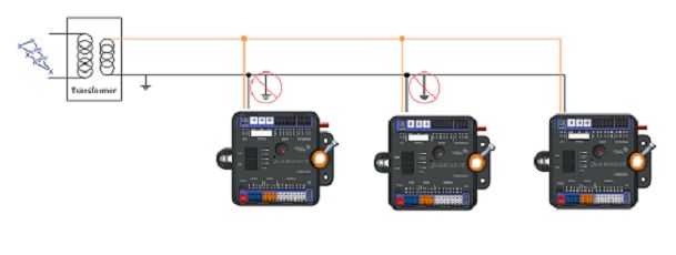
8.    All models are compact in size and are easily
      installed on VAV boxes. The models have either a
      round shaft up to 13 mm in diameter or a 10 mm                                       CAUTION
      square shaft. Tighten the square coupler bolt to the
      shaft using an 8 mm (5/16 in.) wrench or 10 mm (3/8
      in.) 12-point socket. Tighten to 10.5 to 11.5 N·m (95 to      Risk of Electric Shock.
      105 lb·in).                                                   Disconnect the power supply before making electrical
9.    Loop the pneumatic tubing (supplied by field                  connections to avoid electric shock.
      personnel) to include a trap for condensation. Attach
      the needed length of tubing (supplied and installed
      by field personnel) to the dual port fitting on the
      controller and the other ends of the tubing to the
      pressure transducer in the VAV box application (see                                ATTENTION
      Figure 1).
            Note: The CVM/CVE uses a digital pressure               Risque de décharge électrique.
            sensor with bidirectional flow operation, which
            allows you to connect the high- and low-                Débrancher l'alimentation avant de réaliser tout
            pressure DP tubes to either barbed fitting              raccordement électrique afin d'éviter tout risque de
            on the controller. You do not need to make a            décharge électrique.
            specific high- or low-side connection when you
            attach the tubing to the barbed fittings on the
            CVM/CVE.                                                  Important: Do not connect supply power to the
10. Push the Manual Override button, and turn the                     controller before finishing wiring and checking all
    actuator coupling manually to ensure that the                     wiring connections. Short circuits or improperly
    actuator can rotate from full-closed to full-open                 connected wires can result in damage to the
    positions without binding.                                        controller and void any warranty.
11. Complete the mounting by rotating the damper to                   Important: Do not exceed the controller electrical
    the full-open position.                                           ratings. Exceeding controller electrical ratings can
                                                                      result in permanent damage to the controller and
                                                                      void any warranty.

                             CAUTION                                  Important: Use copper conductors only. Make
                                                                      all wiring in accordance with local, national, and
                                                                      regional regulations.
     Risk of Property Damage.                                         Important: Electrostatic discharge can damage
     Rotate the damper to the full-open position before               controller components. Use proper electrostatic
     starting the air handler. Failure to rotate the damper to        discharge precautions during installation, setup, and
                                                                      servicing to avoid damaging the controller.
     the full-open position may result in damage to the VAV
     box or ductwork when the air handler is started.            For information on configuring and wiring a BACnet/
                                                                 IP network, refer to the Metasys IP Networks for BACnet/
                                                                 IP Controllers Configuration Guide (LIT-12012458). For
                                                                 detailed information about configuring and wiring
                                                                 an MS/TP Bus, FC Bus, or SA Bus, refer to the MS/TP
                           ATTENTION                             Communications Bus Technical Bulletin (LIT-12011034). For
                                                                 detailed information about wiring an N2 network, refer to
                                                                 the N2 Communications Bus Technical Bulletin (LIT-636018).
     Risque de dégâts matériels.
     Faire pivoter le registre pour le placer en position
                                                                 Terminal blocks and bus ports
     d'ouverture complète avant de démarrer l'unité de           See Physical features for terminal block and bus port
     traitement d'air. Le non-respect de cette directive         locations on the CVM/CVE controllers. Observe the
     risque d'endommager le caisson de l'unité à volume          following guidelines when wiring a CVM/CVE controller.
     d'air variable (VAV) ou le réseau de conduites au           Input and Output terminal blocks
     démarrage de l'unité de traitement d'air.
                                                                 CV series controllers have removable input and output
                                                                 terminal blocks. The input terminals are located on the
                                                                 bottom of the controller and output terminal blocks are
Wiring                                                           located on the top of the controller. For information about
Observe the following guidelines when wiring a CVM/CVE           removing a terminal block, see Removing a terminal
controller:                                                      block. For more information about I/O terminal functions,
                                                                 requirements, and ratings, see Table 5.

4       M4-CV Series VAV Box Controllers Installation Guide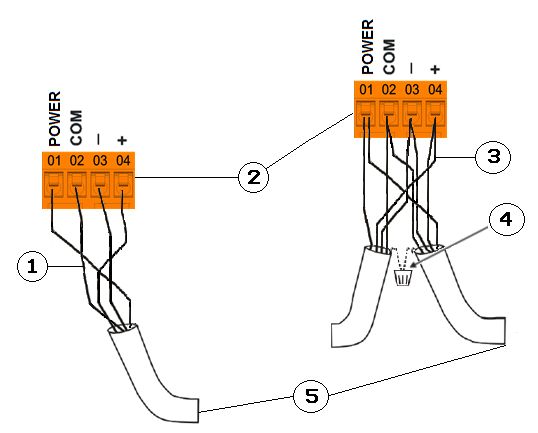
BACnet/IP Ethernet Network Topology for                       Table 2: FC Bus configuration
CVE controllers                                                        Description
CVE controllers may be connected to a BACnet/IP building      1        Wiring for a terminating device on the FC Bus
automation network in multiple ways: as daisy-chained
devices, as part of a star (also called home run) type        2        FC Bus terminal blocks
network, or as part of a ring network.                        3        Wiring for a daisy-chained device on an FC Bus segment
To daisy-chain CVE controllers, connect the controllers       4        Connects to the next device on the FC Bus
to the bus supervisor in a chain with the Ethernet cable
connecting to the CVE at the ETH-1 or ETH-2 port, and         5        Isolated Shield connection terminal
connecting to the next device from the other port.
Benefits of daisy-chained networks are that they require
less physical wiring and new devices can be added easily            Note: The Shield terminal (SHD) on the FC Bus
to the network.                                                     terminal block is isolated and can be used to connect
                                                                    the cable shields on the bus (Figure 5).
In a star network, each CVE controller is connected
by Ethernet cable directly back to a main switch. This        SA Bus terminal block
configuration reduces the possibility of network failure
                                                              The SA Bus terminal block is an orange, removable, 4-
but requires more wiring to install.
                                                              pin terminal block with +15 VDC that fits into a board-
A ring network is a chain of controllers virtually closed     mounted pin header.
by a software component in an Ethernet switch. Not
                                                              When connecting an SA Bus device to the controller, wire
all switches support the ring topology. The dual-port
                                                              the SA Bus terminal block on the controller and other
controller from Johnson Controls supports Media
                                                              SA Bus devices in a daisy-chain configuration using 4-
Redundancy Protocol (MRP). With MRP, a ring of Ethernet
                                                              wire twisted, shielded cable as shown in Figure 6. For
devices can overcome any single communication failure,
                                                              more information about SA Bus terminal functions,
with a recovery time faster than a non-ring (daisy chain or
                                                              requirements, and ratings, see Table 7.
star) architecture.
For more information about network topologies for             Figure 6: SA Bus terminal block wiring
Metasys BACnet/IP Controllers, refer to the Metasys IP
Networks for BACnet/IP Controllers Configuration Technical
Bulletin (LIT-12012458).

FC Bus terminal block (or N2 protocol as
required) on CVM controllers
The FC Bus terminal block is a blue, removable, 4-pin
terminal block that fits into a board-mounted pin header.
When connecting the CVM to the FC Bus, wire the bus
terminal blocks on the controller and other FC Bus devices
in a daisy-chain configuration using 3-wire twisted,
shielded cable as shown in Figure 5. For more information
about FC Bus terminal functions, requirements, and
ratings, see Table 7.

Figure 5: FC Bus terminal block wiring

                                                              Table 3: SA Bus configuration
                                                                      Description

                                                              1       Wiring for a terminating device on SA Bus
                                                              2       SA Bus terminal blocks
                                                              3       Wiring for a daisy chained device on SA Bus
                                                              4       Cable shield connection
                                                                           Note: Connect the shields to ensure they are
                                                                           continuous the entire length with only one ground
                                                                           location.
                                                              5       Connects to the next device on the SA Bus

                                                                  M4-CV Series VAV Box Controllers Installation Guide       5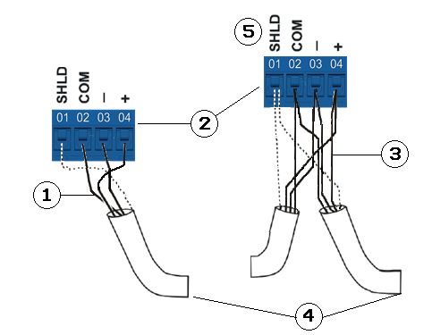
Note: Stranded, 4-wire (2 twisted pair) shielded         Supply power terminal block
     cable. One twisted pair is the + and - leads. The        The 24 VAC supply power terminal block is a gray,
     second pair is COM and POWER.                            removable, 2-pin terminal block that fits into a board-
                                                              mounted pin header on the upper left of the controller.
     Note: Do not use the modular SA Bus port and the
     terminal block SA Bus simultaneously. Only use one       Wire the 24 VAC supply power wires from the transformer
     of these connections at a time.                          to the HOT and COM terminals on the terminal block as
                                                              shown in Figure 8. For more information about Supply
     Note: The CVM/CVE controller is the EOL for the SA       Power terminal functions, requirements, and ratings, see
     Bus.                                                     Table 7.

Sensor (SA Bus) Port                                          Figure 8: 24 VAC supply power terminal block wiring
The Sensor (SA Bus) port is an RJ-12, 6-position modular
jack that provides a connection for the Mobile Access
Portal (MAP) Gateway, the VAV Balancing Tool, specified
network sensors, or other SA Bus devices with RJ-12 plugs.
A DIS1710 Local Controller Display can also be connected
to the SA Bus port.
     Note: Do not use the modular SA Bus port and the
     terminal block SA Bus simultaneously. Only use one
     of these connections at a time.
The Sensor port is connected internally to the SA
Bus terminal block. For more information about
Sensor port functions, requirements, and ratings, see
Communications bus and supply power terminal blocks,
ratings, and requirements.

Figure 7: Pin number assignments for sensor, SA Bus,               Note: The order of the HOT and COM terminals on
and FC Bus ports on Equipment Controllers                          the CV series controllers is reversed from the order
                                                                   of the terminals on the CG series controllers.
                                                              Table 4: Supply power terminal block wiring
                                                                   Description

                                                              1    Supply power terminal block
                                                              2    Supply power terminal header
                                                              3    Wires from Johnson Controls 24 VAC, class 2 power
                                                                   transformer
                                                              4    COM (Brown wire)
                                                              5    24 VAC (Orange wire)

                                                                   Note: The supply power wire colors may be different
                                                                   on transformers from other manufacturers. Refer to
                                                                   the transformer manufacturer’s instructions and the
                                                                   project installation drawings for wiring details.
FC Bus Port on CVM models
                                                                   Important: Connect 24 VAC supply power to
The FC Bus port on the front of the controller is an RJ-12,
                                                                   the controller and all other network devices so
6-position modular jack that provides a connection for the
                                                                   that transformer phasing is uniform across the
Mobile Access Portal (MAP) Gateway or the ZFR/ZFR Pro
                                                                   network devices. Powering network devices with
Wireless Field Bus Router.
                                                                   uniform 24 VAC supply power phasing reduces
The FC Bus port is connected internally to the FC Bus              noise, interference, and ground loop problems.
terminal block. For more information about the FC                  The controller does not require an earth ground
Bus port functions, requirements, and ratings, see                 connection. However, when grounding the
Communications bus and supply power terminal                       secondary of the 24 VAC transformer is required,
blocks, ratings, and requirements. The FC Bus port pin             only one connection to ground must be made near
assignment is shown in Figure 7.                                   the transformer. See Figure 9.
     Note:
     • When the CVM is configured for N2 network
       communication, the FC Bus port is not used.

6     M4-CV Series VAV Box Controllers Installation Guide
Figure 9: Transformer grounding Terminal wiring guidelines, functions,
ratings, and requirements
This section provides further guidelines on input and
output wiring, maximum cable length versus load current,
and SA Bus and supply power wiring.
For information about removing a terminal block from the
controller, see Removing a terminal block.
Input and Output wiring guidelines
Table 5 provides information and guidelines about the
functions, ratings, and requirements for the controller
input and output terminals, and Table 5 also references
CAUTION guidelines for determining proper wire sizes and cable
lengths.
In addition to the wiring guidelines in Table 5, observe the
Risk of Property Damage: following guidelines when wiring controller inputs and
Do not apply power to the system before checking all outputs:
wiring connections. Improper wiring of this terminal • Run all low-voltage wiring and cables separate from
may cause a short circuit across the 24 VAC power high-voltage wiring.
supply. A short circuit may result in a tripped circuit • All input and output cables, regardless of wire size or
breaker or blown fuse. If using a transformer with a number of wires, must consist of twisted, insulated,
built-in fuse, the transformer may need to be replaced. and stranded copper wires.
• Shielded cable is not required for input or output
cables but is recommended for input and output cables
that are exposed to high electromagnetic or radio
frequency noise.
ATTENTION • Cable runs of less than 30 m (100 ft) often do not
require an offset in the input/output software setup.
• Cable runs over 30 m (100 ft) often require an offset in
Risque de dommages matériels: the input/output software setup.
Ne mettez pas l’appareil sous tension avant d’avoir
vérifié toutes les connexions du câblage. Le câblage
inadéquat de cette borne peut causer un court-
circuit sur l’alimentation électrique de 24 V c. Un
court-circuit peut causer le déclenchement du
disjoncteur ou le grillage d’un fusible. Si vous utilisez
un transformateur avec un fusible intégré, vous
pourriez devoir remplacer le transformateur.
To wire the controller, complete the following steps:
1. Terminate wiring according to the appropriate figure
in Termination diagrams.
2. Wire network sensors and other devices to the SA
Bus.
3. For the CVM model, wire the FC Bus in a daisy
chain. For CVE models, connect the controller to
the BACnet/IP building automation network. See
BACnet/IP Ethernet Network Topology for CVE
controllers for details.
4. Ensure that the CVM03050 is assigned a device
address and the CVE03050 is assigned a controller
number, using the rotary switches. See Setting the
device address on CVM models.
5. Connect the controller to 24 VAC, Class 2 power.
Note: If you are using the CVM03050 controller with
the Wireless Field Bus System, refer to the WNC1800/
ZFR182x Pro Series Wireless Field Bus System Bulletin
(LIT-12012320) or the ZFR1800 Series Wireless Field Bus
System Bulletin (LIT-12011336).
M4-CV Series VAV Box Controllers Installation Guide 7I/O terminal blocks, ratings and requirements
Table 5: I/O terminal blocks, functions, ratings, requirements, and cables
Terminal Block label Terminal labels Function, ratings, and requirements To determine wire size and
maximum cable length
UNIVERSAL +15 V 15 VDC Power Source for active (3-wire) input Same as (Universal) UI-n.
(Inputs) devices connected to the Universal UI-n terminals. Note: Use 3-wire cable for
Provides 35 mA total current. devices that source power
from the +15 V terminal.
UI-n Analog Input - Voltage Mode (0–10 VDC) See Guideline A in Table 6.
10 VDC maximum input voltage
Internal 75k ohm Pulldown
Analog Input - Resistive Mode (0–600k ohm) See Guideline A in Table 6.
Internal 12 V, 15k ohm pull up
Qualified Sensors: 0–2k potentiometer
RTD (1k Nickel [Johnson Controls sensor]
1k Platinum, and A99B Silicon Temperature Sensor)
Negative Temperature Coefficient (NTC) Sensor
10K Type L (10K Johnson Controls Type II is
equivalent to Type L) or 2.252K Type II
Binary Input - Dry Contact Maintained Mode See Guideline A in Table 6.
1 second minimum pulse width
Internal 12 V, 15k ohm pull up
UI-C or UI-Cn Universal Input Common for all Universal IN Same as (Universal) UI-n.
terminals
Note: All Universal UI-C/UI-Cn terminals are
isolated from all other commons.
CONFIGURABLE CO-n Analog Output - Voltage Mode (0–10 VDC) See Guideline A in Table 6.
(Outputs) 10 VDC maximum output voltage
10 mA maximum output current
External 1k to 50k ohm load required
Binary Output 24 VAC Triac See Guideline C in Table 6.
Connects CO-n to CO-C/CO-Cn when activated.
External Power Source:
30 VAC maximum voltage to load
0.5 A maximum output current
1.3 A at 25% duty cycle
40 mA minimum load current
CO-C or CO-Cn Analog Output Signal Common: All Configurable Same as (Configurable) CO-n.
Outputs defined as Analog Outputs share a
common, which is isolated from all other commons
except the Binary Input common.
Binary Output Signal Common: All Configurable
Outputs defined as Binary Outputs are isolated
from all other commons, including other
Configurable Output commons.
BINARY BO-n Binary Output - 24 VAC Triac (Internal Power) See Guideline C in Table 6.
(Outputs) Sources internal 24 VAC power (24~ HOT)
8 M4-CV Series VAV Box Controllers Installation GuideTable 5: I/O terminal blocks, functions, ratings, requirements, and cables
Terminal Block label Terminal labels Function, ratings, and requirements To determine wire size and
maximum cable length
BO-C or BO-Cn Binary Output - 24 VAC Triac (Internal Power) See Guideline C in Table 6.
Connects BO-C/BO-Cn to 24~COM when activated.
Internal Power Source:
30 VAC maximum voltage to load
0.5 A maximum output current
1.3 A at 25% duty cycle
40 mA minimum load current
Cable and wire length guidelines
Table 6 defines cable length guidelines for the various wire sizes that may be used for wiring low-voltage (30 V) Relay Outputs are determined by the load
connected to the relay, and local, national or regional electrical codes.
Table 6: Cable length guidelines for recommended wire sizes
Guideline Wire size/gauge and type Maximum cable length and type Assumptions
A 1.0 mm (18 AWG) stranded copper 457 m (1,500 ft) twisted wire 100 mV maximum voltage drop
0.8 mm (20 AWG) stranded copper 297 m (975 297 m (975 ft) twisted wire Depending on the cable length
ft) twisted wire and the connected input or
output device, you may have
0.6 mm (22 AWG) stranded copper 183 m (600 183 m (600 ft) twisted wire
to define an offset in the setup
ft) twisted wire
software for the input or output
0.5mm (24 AWG) stranded copper 107 m (350 107 m (350 ft) twisted wire point.
ft) twisted wire
B 1.0 mm (18 AWG) stranded copper 229 m (750 ft) twisted wire 100 mV maximum voltage drop
0.8 mm (20 AWG) stranded copper 297 m (975 137 m (450 ft) twisted wire Depending on the cable length
ft) twisted wire and the connected input or
output device, you may have
0.6 mm (22 AWG) stranded copper 183 m (600 91 m (300 ft) twisted wire
to define an offset in the setup
ft) twisted wire
software for the input or output
0.5mm (24 AWG) stranded copper 107 m (350 61 m (200 ft) twisted wire point.
ft) twisted wire
C See figure labeled Maximum Wire Length by See figure labeled Maximum Wire N/A
Current and Wire Size to select wire size/gauge. Length by Current and Wire Size to
Use stranded copper wire. determine cable length.
Use twisted wire cable.
Maximum cable length versus load current Note: Figure 10 applies to low-voltage (Figure 10: Maximum wire length for low-voltage (
Table 7: Communication bus and supply power terminal blocks, functions, ratings, requirements, and cables
Terminal block/Port label       Terminal labels      Function, electrical ratings/            Recommended cable type
                                                     Requirements
SA BUS
       1
                                +                    SA Bus Communications                    0.6 mm (22 AWG) stranded, 4-wire
                                -                                                             (2 twisted-pairs), shielded cable
                                                                                              recommended
                                COM                  SA Bus Signal Reference and 15 VDC
                                                     Common                                        Note: The + and - wires are one
                                                                                                   twisted pair, and the COM and
                                POWER                15 VDC Supply Power for Devices on the
                                                                                                   POWER wires are the second
                                                     SA Bus                                        twisted pair.
SA BUS (Port)
             1
                                SA BUS (CVM)         RJ-12 6-Position Modular Port provides 24 AWG 3-pair CAT 3 Cable
Table 8: Termination details
Type of Field Device Type of Input/ Termination diagrams
Output
Voltage Input (Self- UI
Powered)
Temperature Sensor UI
Dry Contact UI
0–10 VDC Output to CO
Actuator (External
Source)
0–10 VDC Output to CO
Actuator (Internal
Source)
24 VAC Triac Output CO
(Switch Low, External
Source)
Note: Applies to CO4 and CO5.
12 M4-CV Series VAV Box Controllers Installation GuideTable 8: Termination details
Type of Field Device Type of Input/ Termination diagrams
Output
Incremental Control CO
to Actuator (Switch
Low, External Source)
Note: Applies to CO4 and CO5.
Analog Output CO
(Voltage)
Incremental Control BO
to Actuator (Switch
Low, Internally
Sourced)
Note: Applies to BO3 (for only), BO1, and BO2.
24 VAC Binary BO
Output (Switch Low,
Internally Sourced)
Network Stat with SA Bus
Phone Jack (Fixed
Address = 199)
M4-CV Series VAV Box Controllers Installation Guide 13Table 8: Termination details
Type of Field Device Type of Input/ Termination diagrams
Output
Network Stat SA Bus
with Terminals
Addressable
Network Stat with SA Bus
Terminals (Fixed
Address = 199)
Setup and adjustments For N2 sites that are converting to BACnet MS/TP, you can
switch the communications protocol of N2-configured
Important: Electrostatic discharge can damage controllers back to BACnet MS/TP.
controller components. Use proper electrostatic
discharge precautions during installation, setup, and To switch the CVM controller operating in N2 mode back
servicing to avoid damaging the controller. into BACnet MS/TP mode, complete the following steps:
Configuring N2 communications (CVM 1. Disconnect the 24 VAC supply from the controller.
models only) 2. Set the address switches to the desired BACnet
MS/TP address. For details about setting a device
About this task: address, see Setting the device address on CVM
N2-capable controllers support the full range of possible models.
N2 device addresses provided by the N2 protocol standard 3. Reconnect the 24 VAC supply to the controller.
(1-254).
4. Using an SA Bus connection, download a controller
To configure a CVM controller to communicate using the application file configured for BACnet MS/TP to the
N2 protocol, complete the following steps: controller.
1. Disconnect the 24 VAC supply from the controller. Configuring wireless communications
2. Set the address switches to the desired N2 address. (CVM models only)
For details about setting a device address, see
About this task:
Setting the device address on CVM models.
To configure a controller for use with the ZFR Pro Series
3. Reconnect the 24 VAC supply to the controller. Wireless Field Bus system, complete the following steps:
4. Using an SA Bus connection, download the
firmware and controller application file configured 1. Disconnect the 24 VAC supply from the controller.
for N2 to the controller. 2. Wire the input/output terminals and SA Bus.
Switching the communications protocol Note: In wireless network applications, do
from N2 to MS/TP not connect any wires to the FC Bus terminal
block. (Connect the SA/FC terminal block on
About this task:
an expansion module to an SA Bus only.)
14 M4-CV Series VAV Box Controllers Installation Guide3. Important: Before the CVM controller is powered Figure 11: Rotary switch block
on, connect the ZFR Pro Wireless Field Bus Router
to the FC Bus port (RJ-12 modular jack) on the front
of the controller.
4. Ensure that the controller's rotary switches are
set to the correct device address. For details about
setting a device address, see Setting the device
address on CVM models.
5. Reconnect the 24 VAC supply to the controller.
Result
For more information about the ZFR Pro Wireless Field
Bus system, refer to the WRG1830/ZFR183x Pro Series
Wireless Field Bus System Technical Bulletin (LIT-12013553).
Setting the device address on CVM
models
Metasys equipment controllers are master devices on MS/
TP (FC or SA) Buses. Before you operate controllers on a
bus, you must set a valid and unique device address for The device address must match the device address
each controller on the bus. defined in the Controller Configuration Tool (CCT) under
The following table describes the valid rotary switch Define Hardware > Network Settings.
device addresses for communications bus applications. To set the device addresses on controllers, complete the
FC Bus communication Valid device address range following steps:
mode 1. Set a unique and sequential device address for each
Wired MS/TP 4-127
of the devices connected on the FC or SA, starting
with device address 4.
communication Note: Addresses 0-3 are
2. To ensure the best bus performance, set sequential
reserved and not for use on
device addresses with no gaps in the device address
equipment controllers.
range (4, 5, 6, 7, 8, 9, and so on). The devices do not
Zigbee wireless 4-127 need to be physically connected on the bus in their
communication Note: Addresses 0-3 are numerical device address order.
reserved and not for use on 3. Write each controller's device address on the white
equipment controllers. label below the Device Address Rotary Switch Block
N2 communication 1-254 on the controller's cover.
Note: Addresses 0 and 255 are For more information about controller device addresses
reserved and not for use on and how to set them on MS/TP Buses, refer to the MS/TP
equipment controllers. Communications Bus Technical Bulletin (LIT-12011034).
Setting the controller number for CVE
The device address is a decimal address set using three
rotary switches located at the top of the controller. The models
numbers are ordered from left to right, most significant The rotary switches on the CGE models are used to set
bit (MSB) to least significant bit (LSB) when the controller the controller number. The controller number can be
is oriented as shown in Figure 1. In the following figure, utilized to physically identify the controller and relate
the switches are set to 1 2 3, designating this controller's it to the building drawings. The factory default BACnet
device address as 123. device ID is calculated from the value of the controller
number added to 2000000. Each equipment controller on
a BACnet/IP network must have a unique BACnet device
ID on the subnet where it resides in order for proper
identification and communication. To ensure a unique
value, the BACnet device ID should be configured in CCT
instead of relying on this default calculation. This step
will be necessary on sites with more than 1000 devices as
controller numbers will be duplicated.
The controller number is set using three rotary switches
and may be numbered from 000 to 999. The numbers are
ordered from left to right, most significant bit (MSB) to
least significant bit (LSB).
In Figure 11, the switches are set to 1 2 3, designating
this controller as controller number 123. The controller
M4-CV Series VAV Box Controllers Installation Guide 15number can be written in the white squares provided so Note: For detailed information about EOL
the controller number can be more easily seen from a termination rules and EOL switch settings on
distance. FC Buses, refer to the MSTP Communications Bus
Technical Bulletin (LIT-12011034).
Removing a terminal block
3. If the controller is a terminating device on the FC
About this task: Bus, set the EOL switch to ON. If the controller is not
To remove a terminal block from the circuit board, a terminating device on the bus, set the EOL switch
complete the following steps: to OFF.
When a controller is connected to power with its EOL
Note: You need a flat blade screwdriver to remove switch set to ON, the amber EOL LED on the controller
the terminal block. cover is illuminated.
1. To prevent any possibility of damage from an Input and output wiring validation
accidental short, remove power from the
controller. The controllers ship with a cooling only, warm or cool
adjust application loaded by default. You can use this
2. Underneath the terminal block, in the small gap
default application to perform wiring verification using
between the bottom of the terminal block and
the MAP Gateway or the DIS1710-0 local controller display.
the circuit board, insert the flat blade of the
screwdriver. To perform wiring validation, ensure that you set the
rotary switches to the desired address or controller
Figure 12: Terminal block number and wire the input and output terminals. Apply
power to the controller. The Fault LED behaves the same
as it does during normal application load. When the Fault
LED turns off, connect to the device with either a MAP
Gateway or DIS1710-0 Local Display to view the points in
the controller.
Commissioning the controllers
3. To detach the left-hand side of the terminal block,
To commission the controller, use the following
position the flat blade underneath the terminal
procedure:
block to the left, and push down the screwdriver
handle. When you do this, you are using the 1. With the desired application loaded in the controller,
screwdriver as a lever to pry up the terminal block. commission the VAV Box. Refer to the Controller Tool
Help (LIT-12011147).
4. To detach the right-hand side of the terminal block,
position the flat blade underneath the terminal 2. Perform airflow balancing on the VAV box.
block to the right, and push down the screwdriver Refer to the VAV Balancing Tool Technical Bulletin
handle. (LIT-12011087).
5. If necessary, repeat steps 3 and 4 until the terminal 3. Perform commissioning checkout procedures. Refer
block is removed. to the Controller Tool Help (LIT-12011147).
You commission equipment controllers with the CCT
Setting the End-of-Line (EOL) switch software.
(CVM models only) Commission controllers using the following connection
types.
Each CVM controller has an EOL switch, which, when
set to ON (up), sets the CVM controller as a terminating Connection CVM CVE
device on the bus. See Physical features for the EOL switch
location. The default EOL switch position is OFF (down). Type
Figure 13: End-of-Line Switch Positions MAP 4.2+/ X X
BACnet Router
Supervisor X X
11
Passthru
Direct Ethernet X
1 Engines need to be at release 9.0 or later.
To set the EOL switch on a CVM controller, complete the When the controller is configured to use the N2 protocol,
following steps: you must use the MAP Gateway at the SA Bus. Wireless
1. Determine the physical location of the controller on connections are not supported in N2 mode. These
the FC Bus. connection options require additional hardware listed in
2. Determine if the controller must be set as a Table 12.
terminating device on the bus.
16 M4-CV Series VAV Box Controllers Installation GuideRefer to the Controller Tool Help (LIT-12011147) and portal, and are loaded and licensed on the computer/
Controller Provisioning with Tools for detailed information server that is running CCT.
about commissioning the controllers. For additional information about the firmware
package files, refer to the CCT Installation Instructions
Firmware package file (LIT-12011259).
The MS-FCP-0 equipment controller firmware package
files are required for CCT to configure and commission Setting a preloaded application
the controllers. The firmware package files also allow you
to upgrade an existing controller to the latest firmware You can configure a CVM/CVE controller to use one of the
release available for that controller. 14 preloaded applications using the MAP Gateway release
Beginning at CCT Release 13, the firmware package files 5.1 or later. Refer to Table 9 for the list of preloaded
are orderable separately; they are not included with CCT. applications. The CVM/CVE controllers ship with the
They are obtained from the Metasys software licensing Cooling Only W/C Adjust application set by default.
Table 9: Preloaded Standard Applications
Application Name Description
Cooling Only W/C Adj Single Duct Cooling Only, Warm/Cool Adjust
Cooling Only SP Adj Single Duct Cooling Only, Setpoint Adjust
Incr HW Reheat W/C Adj Single Duct Incremental Hot Water Reheat, Warm/Cool Adjust
Incr HW Reheat SP Adj Single Duct Incremental Hot Water Reheat, Setpoint Adjust
Elec Reheat 1-3 Stg W/C Adj Single Duct Electric Staged Reheat with 1, 2, or 3 Stages, Warm/Cool
Adjust
Elec Reheat 1-3 Stg Series Fan W/C Adj Single Duct Electric Staged Reheat with 1, 2, or 3 Stages, Single Speed
Series Fan, Warm/Cool Adjust
Elec Reheat 1-3 Stg Series Fan SP Adj Single Duct Electric Staged Reheat with 1, 2, or 3 Stages, Single Speed
Series Fan, Setpoint Adjust
Elec Reheat 1-3 Stg Parallel Fan W/C Adj Single Duct Electric Staged Reheat with 1, 2, or 3 Stages, Parallel Fan,
Warm/Cool Adjust
Elec Reheat 1-3 Stg Parallel Fan SP Adj Single Duct Electric Staged Reheat with 1, 2, or 3 Stages, Parallel Fan,
Setpoint Adjust
Incr HW Reheat Series Fan W/C Adj Single Duct Incremental Hot Water Reheat, Single Speed Series Fan,
Warm/Cool Adjust
Incr HW Reheat Parallel Fan W/C Adj Single Duct Incremental Hot Water Reheat, Parallel Fan, Warm/Cool
Adjust
SCR Elec Reheat W/C Adj Single Duct SCR Electric Reheat/Proportional Heating Valve, Warm/
Cool Adjust
SCR Elec Reheat Series Fan W/C Adj Single Duct SCR Electric Reheat/Proportional Heating Valve, Single
Speed Series Fan, Warm/Cool Adjust
SCR Elec Reheat Parallel Fan W/C Adj Single Duct SCR Electric Reheat/Proportional Heating Valve, Parallel
Fan, Warm/Cool Adjust
Note: All applications use the Imperial unit of Note: These applications only supports the NS8000
measure. series sensors. Older netsensors are no longer
supported.
Note: Warm/Cool Adjust applications also support
sensor only.
Troubleshooting equipment controllers
Table 10 provides LED status indicator information for troubleshooting the controller. General troubleshooting provides
some additional troubleshooting information for possible problems.
Note: If you experience short circuits in the 24 VAC power supply causing protective devices such as breakers or
fuses to trip, make sure that the power connections on the controller are not reversed. The most common cause
of this problem is when the 24 VAC power supply on the controller is reversed but not reversed on a connected
secondary device.
M4-CV Series VAV Box Controllers Installation Guide 17LED status and states
Table 10: Status LEDs and description of LED states
LED label LED color Normal state Descriptions of LED states
POWER Green On Steady Off Steady = No power
On Steady = Power is supplied by primary voltage
FAULT Red Off Steady 2 blinks followed by long pause = Controller powered on in default state.
For more information about this default state, see Input and output wiring
validation .
Blink - 2 Hz = Download or startup in progress, not ready for normal
operation, SA Bus devices offline (such as netsensors)
Rapid blink = SA Bus communications issue
Off Steady = No faults
On Steady = Device fault or no application loaded
FC BUS Green Blink - 2 Hz Blink - 2 Hz = Data transmission (normal communication)
Off Steady = No data transmission (auto baud in progress)
On Steady = communication lost, waiting to join communication bus
SA BUS Green Blink - 2 Hz Blink - 2 Hz = Data transmission (normal communication)
Off Steady = No data transmission (N/A - auto baud not supported)
On Steady = Communication lost; waiting to join communication bus
FC EOL (CVM Amber Off (except on On Steady = EOL is active
models) terminating devices) Off Steady = EOL is not active
ETH-1 (CVE Green Off Off Steady = ETH-1 is not connected
models) Blinking = ETH-1 connected and communicating
ETH-2 (CVE Green Off Off Steady = ETH-2 is not connected
models) Blinking = ETH-2 connected and communicating
FAULT Green Both blink six times in sequence = no valid firmware on the device
and Red
SA BUS
18 M4-CV Series VAV Box Controllers Installation GuideGeneral troubleshooting
Table 11: Troubleshooting
Problem Possible cause and correction Verification
Controller is OFF. Cause: 1. Disconnect the Secondary of the 24
• Transformer has tripped: 1. Transformer is shorted. VAC transformer.
• Power is at Primary of 2. 24 VAC powered sensor is not 2. Use an ohm-meter to measure
Transformer, 0V at Secondary. wired with the same polarity as the between ~24 V HOT and COM; there
• Breaker/Fuse has tripped: controller. must be no short circuit.
• Power is at Primary of 3. SA Bus device is not wired with the
Transformer, 24V at Secondary, 0V same polarity as the controller. Note: Some installations require
at Fuse/Breaker. the secondary of the transformer
to be Earth Grounded. If this is
the case, verify that the Earth
Correction: Ground connection is valid and not
1. Ensure polarity of ~24 V COM / UI-C / shared between multiple pieces of
equipment.
+ 15VC/SA BUS COM on the controller,
auxiliary devices, and I/O is the same.
2. Ensure BO-1, BO-2, and BO-3
terminals of binary outputs are not
connected to ~24 VAC COM, and verify
that BO-C terminals are not connected
to ~24 VAC HOT (these terminals are
internally sourced).
3. Verify the short circuit has been
resolved with an ohm-meter.
4. Reset the breaker/fuse or replace the
transformer.
Note: When replacing the
transformer, it is recommended to
replace with a model that utilizes a
resettable circuit breaker. A circuit
breaker makes solving wiring
problems easier.
Configurable output - analog mode is Cause: 1. Measure the output and verify that it
invalid: There is a power polarity mismatch between matches the command.
0–10 V output is set to 10–100%, but 0 V is at the connected device and the configurable 2. Disconnect the connected device
output terminals. output. and verify the commanded value is
present.
Output is in protection mode, a state the Correction:
analog portion of the configurable output Ensure polarities of ~24 V COM/CO-C match
goes into when it detects a wiring problem. and that the connected end device uses the
The analog output is set to 0% regardless same polarity.
of the command whenever a wiring fault is
detected.
Configurable output - analog mode is Cause: 1. Measure the output and verify that it
invalid: The CO-C terminal is not connected. matches the command.
0–10V output has an undesirable offset of up Correction: 2. Disconnect the connected device
to 1 V. and verify the commanded value is
Connect the CO-C terminal of the
present.
The Common Reference is incorrect. configurable output to the common of the
connected end device.
M4-CV Series VAV Box Controllers Installation Guide 19Accessories
The following table provides the product code number and description for the CV series accessories.
Table 12: CV series controller accessories (order separately)
Product code number Description
XPM Series Expansion Modules Refer to the Metasys CGx, CVx Equipment Controllers and XPM Expansion Modules
Product Bulletin (LIT-12013105) for a complete list of available XPM series
expansion modules.
IOM Series Controllers Refer to the Metasys System Field Equipment Controllers and Related Products
Product Bulletin (LIT-12011042) for a complete list of available IOM Series
Controllers.
TL-CCT-0 License enabling Metasys Controller Configuration Tool (CCT) software for one
user
MS-FCP-0 License enabling Metasys Equipment Controller Firmware Package Files required
for CCT
Mobile Access Portal (MAP) Gateway Refer to the Mobile Access Portal Gateway Catalog Page (LIT-1900869) to identify the
appropriate product for your region.
MS-DIS1710-0 Local Controller Display
NS-ATV7003-0 Handheld VAV Balancing Tool
NS Series Network Sensors Refer to the NS Series Network Sensors Product Bulletin (LIT-12011574) for specific
sensor model descriptions.
AS-CBLTSTAT-0 Cable adapter for connection to 8-pin TE-6700 Series sensors
NS-WALLPLATE-0 Network Sensor Wall Plate
WRZ Series Wireless Room Sensors Refer to the WRZ Series Wireless Room Sensors Product Bulletin (LIT-12000653) for
specific sensor model descriptions.
WRZ-7860-0 Refer to the WRZ-7860 Receiver for One-to-One Wireless Room Sensing Product
Bulletin (LIT-12011640) for a list of available products.
WRZ-SST-120 Wireless System Survey Tool (for use with the lower power 10mW WRZ and
WRZ-7860 systems)
Refer to the WRZ-SST-120 Wireless Sensing System Tool Installation Instructions
(LIT-24-10563-55) for usage instructions.
WRG1830/ZFR183x Pro Wireless Field Bus System This system is used for installations that support BACnet/IP but can also coexist
with the ZFR1800 Series when installed under the same supervisor such as a
network engine.
Refer to the WRG1830/ZFR183x Pro Series Wireless Field Bus System Catalog Page
(LIT-1901026) for a list of available products.
Y64T15-0 Transformer, 120/208/240 VAC Primary to 24 VAC Secondary, 92 VA, Foot Mount,
72.2 cm (30 in.), Primary Leads and 76.2 cm (30 in.) Secondary Leads, Class 2
Y65A13-0 Transformer, 120 VAC Primary to 24 VAC Secondary, 40 VA, Foot Mount (Y65AS),
20.32 cm (8 in.), Primary Leads and 76.2 cm (30 in.) Secondary Leads, Class 2
Y65T31-0 Transformer, 120/208/240 VAC Primary to 24 VAC Secondary, 40 VA, Foot Mount
(Y65AR+), 20.32 cm (8 in.), Primary Leads and Secondary Screw Terminals, Class 2
Y65T42-0 Transformer, 120/208/240 VAC Primary to 24 VAC Secondary, 40 VA, Hub Mount
(Y65SP+), 20.32 cm (8 in.), Primary Leads and Secondary Screw Terminals, Class 2
ACC-TBKPWFCSA-0 Power, FC Bus, and SA Bus terminal block replacement kit for SNC, CGM, CGE,
CVM, CVE, and XPM products. Kit includes 5 of each terminal block type. 15
terminal blocks in total.
ACC-TBKINOUT-0 Input and Output terminal block replacement kit for SNC, CGM, CGE, CVM, CVE,
and XPM products. Kit includes 5 of each 2, 3, and 4 position Input and Output
terminal blocks. 30 terminal blocks in total.
20 M4-CV Series VAV Box Controllers Installation GuideTable 12: CV series controller accessories (order separately)
Product code number Description
MS-FIT100-0 The Field Inspection Tool (FIT) is a portable handheld device with a user interface
that is used to test and troubleshoot the BACnet protocol MS/TP RS-485
communications bus that connects supervisory controllers and equipment
controllers to field point interfaces.
The FIT can be used to check out the wiring of the MS/TP RS-485 bus as well
as verify proper communications of supervisory controllers and equipment
controllers connected to the bus. The FIT can be used on both the FC Bus and SA
Bus.
TL-BRTRP-0 Portable BACnet/IP to MS/TP Router
M4-CVACT-0R Actuator Assembly Replacement Kit for use with M4-CV series controllers
Technical specifications
Table 13: CV Series controllers technical specifications
Description
Power Requirement 24 VAC (nominal, 20 VAC minimum/30 VAC maximum), 50/60 Hz, Power Supply Class 2
(North America), Safety Extra-Low Voltage (SELV) (Europe)
Power Consumption 10 VA typical, 14 VA maximum
Note: The VA rating does not include any power supplied to the peripheral devices
connected to three Outputs (BOs) or Configurable Outputs (COs), which can
consume up to 12 VA for each BO or CO, for a possible total consumption of an
additional 60 VA (maximum). There are 3 BO's and 2 CO's that can each draw 12VA
for a total of 60VA additional power.
Note: The USB feature is not currently supported.
Power Source +15 VDC power source terminals provide 35 mA total current. Quantity 1 located in
Universal IN terminals - for active (3-wire) input devices
Ambient Conditions Operating: 0°C to 50°C (32°F to 122°F) 10% to 90% RH noncondensing
Storage: -40°C to 70°C (-40°F to 158°F) 5% to 95% RH noncondensing
Network Engines M4-CVM models: All network engine model types
M4-CVE03050-0P: All network engine model types at R9.0 or later
Communications Protocol M4-CVM models: BACnet MS/TP; N2. Zigbee Wireless also supported (at FC Bus and for
Sensors) with additional hardware.
M4-CVE03050-0P: BACnet/IP
Controller Number for Ethernet Set of three rotary switches used to set controller number between 000 and 999. See
Controllers Setting the controller number for CVE models.
Device Addressing for BACnet MS/TP Decimal address set via three rotary switches; valid controller device addresses 4-127
Device Addressing for N2 Decimal address set via three rotary switches: valid controller device addresses 1-254
Communications Bus M4-CVM models: BACnet MS/TP (default), N2
Note: For more information, refer to 3-wire FC Bus between the supervisory controller and equipment controllers
the MS/TP Communications Bus Technical M4-CVE models:
Bulletin (LIT-12011034)
BACnet/IP
Two Ethernet ports; 10/100 Mbps; 8-pin RJ-45 connector
M4-CVM and M4-CVE models:
4-wire SA Bus between equipment controller, network sensors and other sensor/actuator
devices, includes a lead to source 15 VDC supply power (from equipment controller) to
bus devices
Processor RX64M 32-bit Renesas microcontroller
Memory 16MB Flash Memory and 8MB SDRAM
Real-Time Clock Backup Power Supply Super capacitor maintains power to the onboard real-time clock for a minimum of 72
hours when supply power to the controller is disconnected.
M4-CV Series VAV Box Controllers Installation Guide 21Table 13: CV Series controllers technical specifications
Description
Input and Output Capabilities 3 - Universal Inputs: Defined as 0–10 VDC, 0–600k ohms, or Binary Dry Contact
2 - Configurable Outputs: Defined as 0-10 VDC or 24 VAC Triac BO
3 - Binary Outputs: Defined as 24 VAC Triac (external power source only)
Universal Input (UI) Resolution/ UI Analog Input Mode: 15-bit resolution on UIs
Configurable Output (CO) Accuracy CO Analog Output Mode: 0–10 VDC ± 200 mV
Air Pressure Differential Sensor Range: -2 in. to 2 in. H2O
Performance Characteristics:
Typical Accuracy at ambient operating conditions: +/- 0.5 % in. H2O full scale
Typical accuracy at zero (null) pressure is +/- 0.0006 in. H2O
Actuator Rating 4 N·m (35 lb·in) minimum shaft length = 44 mm (1-3/4 in.) (if provided)
Terminations Inputs/Outputs: Pluggable Screw Terminal
FC Bus, SA Bus, and Supply Power: 4-Wire and 2-Wire Pluggable Screw Terminal Blocks
FC and SA Bus Modular Ports: RJ-12 6-Pin Modular Jacks
Note: The FC Bus Terminal and FC Bus Port are only available on the CVM models
Mounting Mounts to damper shaft using single set screw and to duct with single mounting screw
Housing Enclosure material: ABS and polycarbonate UL94 5VB; Self-extinguishing
Protection Class: IP20 (IEC529)
Dimensions 165 mm x 125 mm x 73 mm (6.5 in. x 4.92 in. x 2.9 in.)
(Height x Width x Depth) Center of Output Hub to Center of Captive Spacer: 135 mm (5-5/16 in.)
Weight 0.69 kg (1.52 lb)
Compliance United States:
UL Listed, File E107041, CCN PAZX, UL 916, Energy Management Equipment.
FCC Compliant to CFR47, Part 15, Subpart B, Class A.
Suitable for Use in Other Environmental Air Space (Plenums) in Accordance with Section
300.22(C) of the National Electrical Code.
Canada:
UL Listed, File E107041, CCN PAZX7, CAN/CSA C22.2 No. 205, Signal Equipment.
Industry Canada Compliant, ICES-003
Europe:
CE Mark – Johnson Controls declares that this product is in compliance with the essential
requirements and other relevant provisions of the EMC Directive and RoHS Directive.
Australia and New Zealand:
RCM Mark, Australia/NZ Emissions Compliant.
BACnet International: BACnet Testing Laboratories™ (BTL) Protocol Revision 18 Listed
and Certified BACnet Advanced Application Controller (B-AAC), based on ANSI/ASHRAE
135-2016
The performance specifications are nominal and conform to acceptable industry standard. For application at conditions beyond
these specifications, consult the local Johnson Controls office. Johnson Controls shall not be liable for damages resulting from
misapplication or misuse of its products.
Repair information Product warranty
If the equipment controller fails to operate within its This product is covered by a limited warranty, details
specifications, replace the unit. For a replacement unit, of which can be found at www.johnsoncontrols.com/
contact the nearest Johnson Controls representative. buildingswarranty.
Software terms
Use of the software that is in (or constitutes)
this product, or access to the cloud, or hosted
22 M4-CV Series VAV Box Controllers Installation GuideYou can also read