LEC-2580 User Manual - Embedded Computing Platform - Version: 1.7 Date of Release: 2024-01-19
←
→
Page content transcription
If your browser does not render page correctly, please read the page content below
Embedded Computing Platform
Hardware Platforms for Intelligent Edge Computing

    LEC-2580
    User Manual

                                                    Version: 1.7
                                   Date of Release: 2024-01-19

                                    1

                                                          Version: 2.5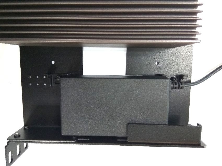
About this Document
This manual describes the overview of the various functionalities of this product, and the information you
need to get it ready for operation. It is intended for those who are:
- responsible for installing, administering and troubleshooting this system or Information Technology
   professionals.
- assumed to be qualified in the servicing of computer equipment, such as professional system integrators, or
   service personnel and technicians.

The latest version of this document can be found on Lanner’s official website, available either through the
product page or through the Lanner Download Center page with a login account and password.

Conventions & Icons
The icons are used in the manual to serve as an indication of interest topics or important messages.
                  Icon                                                 Usage

                                       This mark indicates that there is something you should pay special
             Note or Information       attention to while using the product.

                                       This mark indicates that there is a caution or warning and it is
          Warning or Important         something that could damage your property or product.

Online Resources
To obtain additional documentation resources and software updates for your system, please visit the Lanner
Download Center. As certain categories of documents are only available to users who are logged in, please be
registered for a Lanner Account at http://www.lannerinc.com/ to access published documents and
downloadable resources.

Technical Support
In addition to contacting your distributor or sales representative, you could submit a request at our Lanner
Technical Support and fill in a support ticket to our technical support department.

Documentation Feedback
Your feedback is valuable to us, as it will help us continue to provide you with more accurate and relevant
documentation. To provide any feedback, comments or to report an error, please email
contact@lannerinc.com. Thank you for your time.

Revision History
   Revision              Date                                         Description
       0.1           August 3, 2016     Preliminary
       1.0          August 22, 2016     Official release

                                        Added LTE module installation
       1.1          January 24, 2017
                                        Modified power input voltage

                                                           2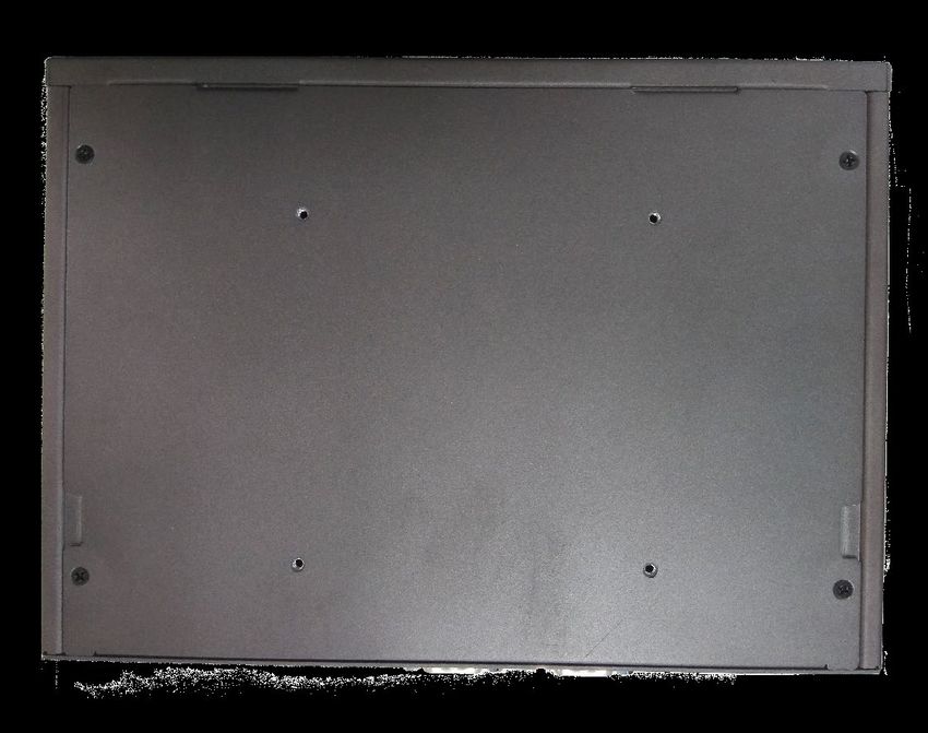
Modified operating temperature

                                       Added PoE configuration description

                                       Added warning statement in the installation precaution
                                       Added wall mounting section

       1.2         July 17th, 2017     Changed front panel image

       1.3          Sep 6th, 2017      Added Rackmounting section

                                       Modified Specifications and specified the working temperature for
       1.4          Oct 19th, 2017
                                       PoE models.

       1.5         Nov 15th, 2017      Modified LTE Wireless Network Module model name

Copyright and Trademarks
This document is copyrighted © 2024 by Lanner Electronics Inc. All rights are reserved. The original
manufacturer reserves the right to make improvements to the products described in this manual at any time
without notice. No part of this manual may be reproduced, copied, translated or transmitted in any form or by
any means without the prior written permission of the original manufacturer. Information provided in this
manual is intended to be accurate and reliable. However, the original manufacturer assumes no responsibility
for its use, nor for any infringements upon the rights of third parties that may result from such use.

                                                      3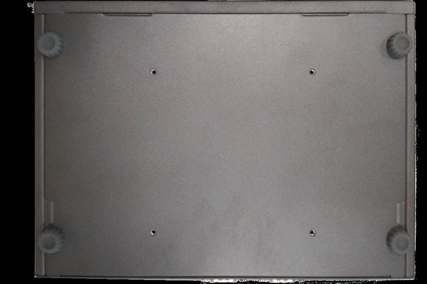
Contact Information
Taiwan Corporate Headquarters                China
Lanner Electronics Inc.                      Beijing L&S Lancom Platform Tech. Co., Ltd.
7F, No.173, Sec.2, Datong Rd.                Guodong LOFT 9 Layer No. 9 Huinan Road,
Xizhi District, New Taipei City 22184,       Huilongguan Town, Changping District, Beijing
Taiwan                                       102208 China
立端科技股份有限公司                                   T: +86 010-82795600
221 新北市汐止區                                   F: +86 010-62963250
大同路二段 173 號 7 樓                              E: service@ls-china.com.cn
T: +886-2-8692-6060
F: +886-2-8692-6101
E: contact@lannerinc.com

USA                                          Canada
Lanner Electronics Inc.                      Lanner Electronics Canada Ltd
47790 Westinghouse Drive                     3160A Orlando Drive
Fremont, CA 94539                            Mississauga, ON
T: +1-855-852-6637                           L4V 1R5 Canada
F: +1-510-979-0689                           T: +1 877-813-2132
E: sales_us@lannerinc.com                    F: +1 905-362-2369
                                             E: sales_ca@lannerinc.com

Europe
Lanner Europe B.V.
Wilhelmina van Pruisenweg 104
2595 AN The Hague
The Netherlands
T: +31 70 701 3256
E: sales_eu@lannerinc.com

                                         4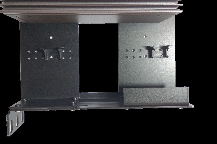
Acknowledgment
Intel® and Intel® Atom® are trademarks of Intel Corporation or its subsidiaries in the U.S. and/or other countries.
Microsoft Windows and MS-DOS are registered trademarks of Microsoft Corp.
All other product names or trademarks are properties of their respective owners.

Federal Communication Commission Interference Statement
This equipment has been tested and found to comply with the limits for a Class A digital device, pursuant to Part 15 of FCC
Rules. These limits are designed to provide reasonable protection against harmful interference in a residential installation.
This equipment generates, uses and can radiate radio frequency energy and, if not installed and used in accordance with the
instruction, may cause harmful interference to radio communications. However, there is no guarantee that interference will
not occur in a particular installation. If this equipment does cause harmful interference to radio or television reception, which
can be determined by turning the equipment off and on, the user is encouraged to try to correct the interference by one or
more of the following measures:
Reorient or relocate the receiving antenna.
Increase the separation between the equipment and receiver.
Connect the equipment into an outlet on a circuit different from that to which the receiver is connected.
Consult the dealer or an experienced radio/TV technician for help.

FCC Caution
Any changes or modifications not expressly approved by the party responsible for compliance could void the user's authority
    to operate this equipment.
This transmitter must not be co-located or operating in conjunction with any other antenna or transmitter.

         Note
 1. An unshielded-type power cord is required to meet FCC emission limits and to prevent interference to the nearby radio and
    television reception. It is essential that only the supplied power cord be used.
 2. Use only shielded cables to connect I/O devices to this equipment.
 3. Changes or modifications not expressly approved by the party responsible for compliance could void the user’s authority to
    operate the equipment.

       Important
 1. Operations in the 5.15-5.25GHz band are restricted to indoor usage only.
 2. This device meets all the other requirements specified in Part 15E, Section 15.407 of the FCC Rules.

                                                                 5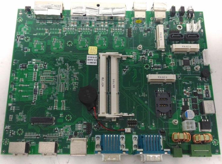
Safety Guidelines
Follow these guidelines to ensure general safety:
Keep the chassis area clear and dust-free during and after installation.
Do not wear loose clothing or jewelry that could get caught in the chassis. Fasten your tie or scarf and roll up your sleeves.
Wear safety glasses if you are working under any conditions that might be hazardous to your eyes.
Do not perform any action that creates a potential hazard to people or makes the equipment unsafe.
Disconnect all power by turning off the power and unplugging the power cord before installing or removing a chassis or
    working near power supplies
Do not work alone if potentially hazardous conditions exist.
Never assume that power is disconnected from a circuit; always check the circuit.

Consignes de sécurité
Suivez ces consignes pour assurer la sécurité générale :
Laissez la zone du châssis propre et sans poussière pendant et après l’installation.
Ne portez pas de vêtements amples ou de bijoux qui pourraient être pris dans le châssis. Attachez votre cravate ou écharpe
    et remontez vos manches.
Portez des lunettes de sécurité pour protéger vos yeux.
N’effectuez aucune action qui pourrait créer un danger pour d’autres ou rendre l’équipement dangereux.
Coupez complètement l’alimentation en éteignant l’alimentation et en débranchant le cordon d’alimentation avant d’installer
    ou de retirer un châssis ou de travailler à proximité de sources d’alimentation.
Ne travaillez pas seul si des conditions dangereuses sont présentes.
Ne considérez jamais que l’alimentation est coupée d’un circuit, vérifiez toujours le circuit. Cet appareil génère, utilise et
    émet une énergie radiofréquence et, s’il n’est pas installé et utilisé conformément aux instructions des fournisseurs de
    composants sans fil, il risque de provoquer des interférences dans les communications radio.

Lithium Battery Caution
There is risk of Explosion if Battery is replaced by an incorrect type.
Dispose of used batteries according to the instructions.
Installation only by a skilled person who knows all Installation and Device Specifications which are to be applied.
Do not carry the handle of power supplies when moving to another place.
Please conform to your local laws and regulations regarding safe disposal of lithium BATTERY.
Disposal of a battery into fire or a hot oven, or mechanically crushing or cutting of a battery can result in an explosion.
Leaving a battery in an extremely high temperature environment can result in an explosion or the leakage of flammable
    liquid or gas.
A battery subjected to extremely low air pressure may result in an explosion or the leakage of flammable liquid or gas.

Avertissement concernant la pile au lithium
Risque d’explosion si la pile est remplacée par une autre d’un mauvais type.
Jetez les piles usagées conformément aux instructions.
L’installation doit être effectuée par un électricien formé ou une personne formée à l’électricité connaissant toutes les
    spécifications d’installation et d’appareil du produit.
Ne transportez pas l’unité en la tenant par le câble d’alimentation lorsque vous déplacez l’appareil.

Operating Safety
Electrical equipment generates heat. Ambient air temperature may not be adequate to cool equipment to acceptable
    operating temperatures without adequate circulation. Be sure that the room in which you choose to operate your system
    has adequate air circulation.
Ensure that the chassis cover is secure. The chassis design allows cooling air to circulate effectively. An open chassis permits
    air leaks, which may interrupt and redirect the flow of cooling air from internal components.
Electrostatic discharge (ESD) can damage equipment and impair electrical circuitry. ESD damage occurs when electronic
    components are improperly handled and can result in complete or intermittent failures. Be sure to follow ESD-prevention
    procedures when removing and replacing components to avoid these problems.
Wear an ESD-preventive wrist strap, ensuring that it makes good skin contact. If no wrist strap is available, ground yourself
    by touching the metal part of the chassis.

                                                               6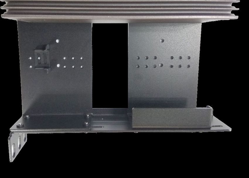
Periodically check the resistance value of the antistatic strap, which should be between 1 and 10 megohms (Mohms).

Sécurité de fonctionnement
L’équipement électrique génère de la chaleur. La température ambiante peut ne pas être adéquate pour refroidir
    l’équipement à une température de fonctionnement acceptable sans circulation adaptée. Vérifiez que votre site propose
    une circulation d’air adéquate.
Vérifiez que le couvercle du châssis est bien fixé. La conception du châssis permet à l’air de refroidissement de bien circuler.
    Un châssis ouvert laisse l’air s’échapper, ce qui peut interrompre et rediriger le flux d’air frais destiné aux composants
    internes.
Les décharges électrostatiques (ESD) peuvent endommager l’équipement et gêner les circuits électriques. Des dégâts d’ESD
    surviennent lorsque des composants électroniques sont mal manipulés et peuvent causer des pannes totales ou
    intermittentes. Suivez les procédures de prévention d’ESD lors du retrait et du remplacement de composants.
Portez un bracelet anti-ESD et veillez à ce qu’il soit bien au contact de la peau. Si aucun bracelet n’est disponible, reliez votre
    corps à la terre en touchant la partie métallique du châssis.
Vérifiez régulièrement la valeur de résistance du bracelet antistatique, qui doit être comprise entre 1 et 10 mégohms
    (Mohms).

Mounting Installation Precaution
Do not install and/or operate this unit in any place that flammable objects are stored or used in.
If installed in a closed or multi-unit rack assembly, the operating ambient temperature of the rack environment may be
     greater than room ambient. Therefore, consideration should be given to installing the equipment in an environment
     compatible with the maximum ambient temperature (Tma) specified by the manufacturer.
Installation of the equipment (especially in a rack) should consider the ventilation of the system’s intake (for taking chilled
     air) and exhaust (for emitting hot air) openings so that the amount of airflow required for safe operation of the equipment
     is not compromised.
To avoid a hazardous load condition, be sure the mechanical loading is even when mounting.
Consideration should be given to the connection of the equipment to the supply circuit and the effect that overloading of
     the circuits might have on over-current protection and supply wiring. Appropriate consideration of equipment nameplate
     ratings should be used when addressing this concern.
Reliable earthing should be maintained. Particular attention should be given to supply connections other than direct
     connections to the branch circuit (e.g., use of power strips).

Installation & Operation:
This equipment must be grounded. The power cord for product should be connected to a socket-outlet with earthing
    connection.
    Cet équipement doit être mis à la terre. La fiche d'alimentation doit être connectée à une prise de terre correctement
    câblée
Suitable for installation in Information Technology Rooms in accordance with Article 645 of the National Electrical Code and
    NFPA 75.
    Peut être installé dans des salles de matériel de traitement de l'information conformément à l'article 645 du National
    Electrical Code et à la NFPA 75.
The machine can only be used in a restricted access location and must be installed by a skilled person.
    Les matériels sont destinés à être installés dans des EMPLACEMENTS À ACCÈS RESTREINT.

Warning
Class I Equipment. This equipment must be earthed. The power plug must be connected to a properly wired earth ground
   socket outlet. An improperly wired socket outlet could place hazardous voltages on accessible metal parts.
Product shall be used with Class 1 laser device modules.
Avertissement
Équipement de classe I. Ce matériel doit être relié à la terre. La fiche d’alimentation doit être raccordée à une prise de terre
    correctement câblée. Une prise de courant mal câblée pourrait induire des tensions dangereuses sur des parties
    métalliques accessibles.
Le produit doit être utilisé avec des modules de dispositifs laser de classe 1.

     Important
 This unit is intended to be supplied by an UL Listed Adapter/DC power source with mating connector.

                                                                7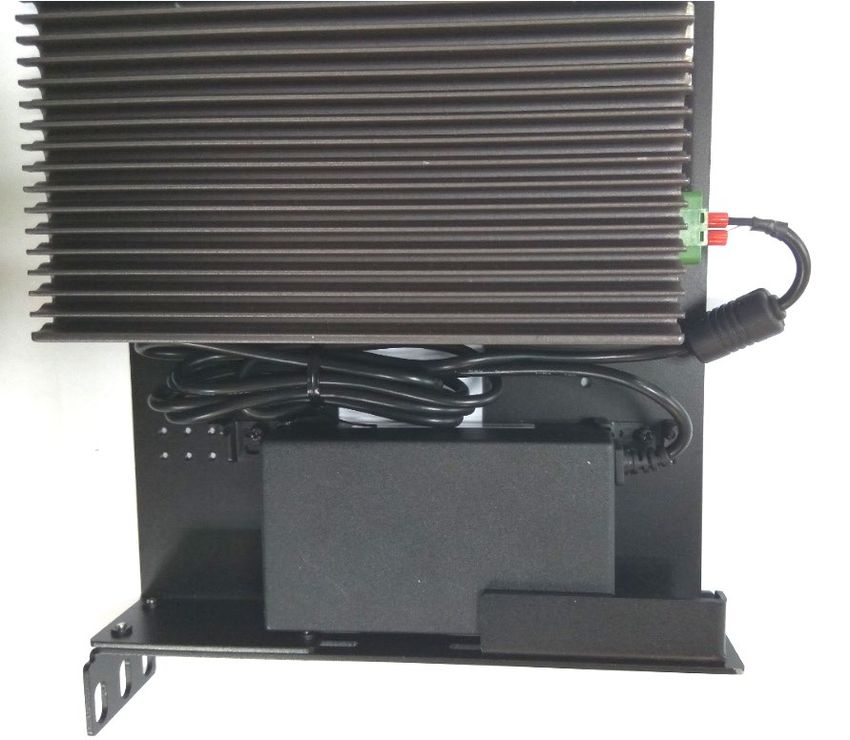
Electrical Safety Instructions
Before turning on the device, ground the grounding cable of the equipment. Proper grounding (grounding) is very
important to protect the equipment against the harmful effects of external noise and to reduce the risk of electrocution in
the event of a lightning strike. To uninstall the equipment, disconnect the ground wire after turning off the power. A
ground wire is required and the part connecting the conductor must be greater than 4 mm2 or 10 AWG.

Consignes de sécurité électrique
Avant d’allumer l’appareil, reliez le câble de mise à la terre de l’équipement à la terre.
Une bonne mise à la terre (connexion à la terre) est très importante pour protéger l’équipement contre les effets néfastes
   du bruit externe et réduire les risques d’électrocution en cas de foudre.
Pour désinstaller l’équipement, débranchez le câble de mise à la terre après avoir éteint l’appareil.
Un câble de mise à la terre est requis et la zone reliant les sections du conducteur doit faire plus de 4 mm2 ou 10 AWG.

      Important
 The PoE networks without routing to the outside plant that installation instructions clearly state, therefore,
 these circuits are not considered external circuit.

                                                            8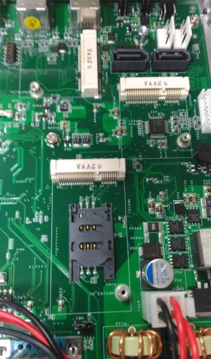
Table of Contents
CHAPTER 1: PRODUCT OVERVIEW ...................................................... 10
    Ordering Information ...................................................................................................................... 10
    System Specifications ...................................................................................................................... 11

CHAPTER 2: SYSTEM OVERVIEW ......................................................... 13
    Mechanical Drawing ........................................................................................................................ 13
    Block Diagram ................................................................................................................................ 14
    Front I/Os ....................................................................................................................................... 15
    Rear I/Os......................................................................................................................................... 16

CHAPTER 3: BOARD LAYOUT ............................................................... 17
    Internal Jumpers & Connectors ......................................................................................................... 17
    Jumper Settings & Connector Pinout (Motherboard) ........................................................................... 18

CHAPTER 4: HARDWARE SETUP .......................................................... 25
    Accessing the Inside of LEC-2580 ....................................................................................................... 25
    Installing SO-DIMM Memory ............................................................................................................. 26
    Installing mSATA and Mini-PCIe Module............................................................................................. 27
    Installing LTE Wireless Network Module ............................................................................................ 28
    Installing Disk Drives ....................................................................................................................... 29
    Wall Mounting ................................................................................................................................ 30
    Rack Mounting ................................................................................................................................ 31

Appendix 1: Watchdog Timer .............................................................. 37

                                                                         9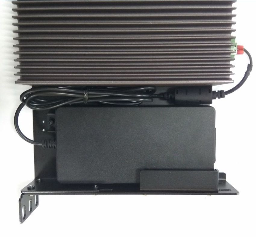
CHAPTER 1: PRODUCT OVERVIEW
Thank you for choosing LEC-2580. This industrial embedded system is empowered by Intel® Core™ i7-6600U,
Core™ i5-6300U and Core™ i3-6100U SoC processors (codenamed Skylake-U). The I/O features include four
RS-232/422/485 serial ports, four USB 3.0, two USB 2.0 ports and two HDMI ports. For networking
communications, the LEC-2580 offers six 10/100/1000 Mbps Ethernet ports while the LEC-2580P, a variant of
the LEC-2580, comes with two 10/100/1000 Mbps Ethernet ports and four PoE ports for even greater
flexibility.
Product Features:
Intel® Core™ i7-6600U/i5-6300U/i3-6100U SoC
2 x DDR3L 1333/1600MHz SO-DIMM sockets supporting up to 16GB
Intel® HD Graphics
2x HDMI display output ports
6x RJ45 (LEC-2580) or 2x RJ45 & 4x PoE (LEC-2580P)
4x USB 3.0 and 2x USB 2.0
2x 2.5” HDD/SSD with RAID 0/1
4x Serial Ports with RS-232/422/485 signals
0°C ~ 60°C Wide Operating Temperature Range (LEC-2580 models)
2x mini-PCIe sockets (1 x full-size and 1 x half-size) with PCIe and USB signals (the full-size socket is
compatible with LTE module)
1x mSATA socket for internal storage
Ordering Information
SKU Description
LEC-2580-711A Embedded industrial PC with Intel i7-6600U
LEC-2580-511A Embedded industrial PC with Intel i5-6300U
LEC-2580-311A Embedded industrial PC with Intel i3-6100U
LEC-2580P-711A Embedded industrial PC with Intel i7-6600U w/ 4-ports PoE
LEC-2580P-511A Embedded industrial PC with Intel i5-6300U w/ 4-ports PoE
LEC-2580P-311A Embedded industrial PC with Intel i3-6100U w/ 4-ports PoE
10System Specifications
CPU Intel® Core™ i7-6600U/i5-6300U/i3- 6100U
Frequency 2.6GHz/2.4GHz/2.3GHz
Processor
Core Number 2C
BIOS AMI 128Mbit SPI Flash BIOS
Fanless Yes
Technology 2x DDR3L 1333/1600MHz SO-DIMM sockets
supporting up to 16GB
Memory
Max. Capacity 16 GB
Socket 2x 204-pin SODIMM
Controller Intel® HD Graphics
Graphic
HDMI 2x HDMI, 3840 x 2160 @24Hz or 2560 x 1600 @60Hz
Controller Intel® i219 and i211
Ports 6 x RJ-45 10/100/1000Mbps ports
Ethernet
4 x RJ-45 LAN ports with PoE function (available in
PoE
LEC-2580P only)
Type SATA III
Installation 1x mSATA Socket
Storage Type SATA III
2x 2.5” HDD/SSD Drive Bay (RAID 0/1) HDD/SSD
Installation
Thickness: 2x 11mm or 1x 16mm
Serial Port 4x RS-232/422/485, DB9 Male
Digital I/O --
USB 2.0 2x Type A
USB 3.0 4x Type A
I/O
Power-On/Reset Button 1x Power On/Off, 1x Reset
Remote Power Switch Yes
LED Power/Storage Access, 3G/Wifi Status
Antenna Hole 2 x SMA Antenna Holes
1x Full-sized Socket with SIM Card Reader and 1x
Expansion Interface Mini-PCIe
Half-sized Socket
Watchdog Timer Watchdog Timer 1~255 Level Time Interval System Reset, Software Programmable
Power Type ATX
Power Supply Voltage +24VDC (12VDC ~ 30VDC)
Power
Connector 2-pin Terminal Block
Power Consumption (Idle) 13W
11Power Consumption
38W
(Full Load)
Optional AC to DC, AC 90V to 240V Input, DC
Power Adaptor
24V/2.5A 60W Adapter
Operating (Note)
0°C~60°C (LEC-2580 models)
Temperature 0°C~50°C (LEC-2580P models)
Storage Temperature -20°C~70°C
Environment
Relative Humidity 5%~95% (Non-condensing)
IEC 60068-2-64, 0.5Grms, Random 5 ~500 Hz, 40
Vibration
Mins/Axis
Dimension (W x H x D) 240 x 60 x 173.8 mm
Construction Aluminum
Mechanical
Weight TBD
Mounting Wall, DIN-rail, Rack, VESA
Microsoft Windows WES7, Win 7 Pro FES, WE 8.1 Industry Pro, Win10 IoT
Driver Support
Linux Kernel 3.12
EMC CE/FCC, Class A
Certification
Safety --
Note: Remember that when the processor's temperature reaches a certain point, it will begin throttling by
lowering its clock speed as a safeguard against thermal damage. Despite this protective feature of the CPU, it's
advisable to maintain the temperature as low as possible using methods like adjusting the fan controls or
improving the airflow within the case.
12CHAPTER 2: SYSTEM OVERVIEW
Mechanical Drawing
Unit: mm
13Block Diagram
14Front I/Os
F1 F2
F3 F4
F5 F5
No. Description
6x 10/100/1000 mbps RJ-45 LAN ports
F1 LAN Port
LAN3-LAN6 are PoE ports
F2 USB Port 4x USB3.0 Type-A ports in dual double-stacked form
2x LED for Power-on status (Green) and Storage access status (Yellow);
F3 LED Indicator
2x LED for 3G & WiFi communication access
F4 Reset Button 1x Reset button
F5 Antenna 2x SMA antenna holes (sealed by default)
15Rear I/Os
R1
R2 R3 R4 R5
No. Description
R1 Power Input 1x 2-pin terminal block, support DC +24V input
R2 Power Button 1x 2-pin terminal block for remote power on/off
R3 COM Port 4x D-sub COM Ports with RS-232/422/485 signals
R4 USB Port 2x USB 2.0 Type-A Ports in double-stacked form
R5 HDMI Port 2x HDMI Ports
16CHAPTER 3: BOARD LAYOUT
Internal Jumpers & Connectors
JSPI1
LAN1-6 USB2
USB1
JTPM1
SATAPWR1-2
SATA1-
MSATA1
MPCIE2
DIMM2
MPCIE1
DIMM1
POE1 JLPC
JVGA1 ATX1
CN1
USB3 JME1
HDMI1-2
COM1-2
JCMOS1
17Jumper Settings & Connector Pinout (Motherboard)
HDMI1: High-Definition Multimedia Interface connector
Pin No. Description Pin No. Description
1 DATA2+ 2 GND
3 DATA2- 4 DATA1+
5 GND 6 DATA1-
7 DATA0+ 8 GND
9 DATA0- 10 CLK+
11 GND 12 CLK-
13 N.C 14 N.C
15 DDC CLK 16 DDC DAT
17 GND 18 HDMI_VCC
19 HPD
HDMI2: High-Definition Multimedia Interface connector
Pin No. Description Pin No. Description
1 DATA2+ 2 GND
3 DATA2- 4 DATA1+
5 GND 6 DATA1-
7 DATA0+ 8 GND
9 DATA0- 10 CLK+
11 GND 12 CLK-
13 N.C 14 N.C
15 DDC CLK 16 DDC DAT
17 GND 18 HDMI_VCC
19 HPD
18LAN1-6: LAN Connectors (RJ-45 connectors with LED) at 10/100/1000Mbps for Ethernet connectivity.
LAN3 to LAN6 are PoE ports.
Pin No. Description
1 TXD+ MD0+
2 TXD- MD0-
3 RX+ MD1+
4 T45 MD2+
5 T45 MD2-
6 RX- MD1-
7 T78 MD3+
8 T78 MD3-
9 10-/100-/1000+
10 10+/100+/1000-
11 Active LED+
12 Active LED-(yellow)
USB1-2: 4 x USB3.0 Type-A Connectors in dual double-stacked form
Pin No. Description Pin No. Description
1 USB_VCC1 2 USB1_D-
3 USB1_D+ 4 GND
5 USB1_RX- 6 USB1_RX+
7 GND 8 USB1_TX-
9 USB1_TX+ 10 USB_VCC1
11 USB1_D- 12 USB1_D+
13 GND 14 USB1_RX-
15 USB1_RX+ 16 GND
17 USB1_TX- 18 USB1_TX+
USB3: USB2.0 Type-A Connectors in double-stacked form
PIN NO. DESCRIPTION
1 USB_VCC1 5 8
2 -USB
3 +USB
4 GND
1 4
0 USB_VCC2
USB3
6 -USB
7 +USB
8 GND
19COM1/COM2: 4 x DB-9 COM ports with RS-232/422/485 signals (COM1-4 on the panel)
Pin Signal Pin Signal
1 Data Carrier Detect (DCDA#) 6 Data Set Ready (DSRA#)
2 Receive Data (RXDA) 7 Request To Send (RTSA#)
3 Transmit Data (TXDA) 8 Clear To Send (CTSA#)
4 Data Terminal Ready (DTRA#) 9 Ring Indicator (RIA#)
5 GND
Pin Assignments for RS-232/422/485
Pin RS-232 RS-422 RS-485
1 DCD TX- RTX-
2 RXD TX+ RTX+
3 TXD RX+
4 DTR RX-
5 GND
6 DSR
7 RTS
8 CTS
9 RI
20MPCIE1: mini-PCIe slot with USB signals and SIM card reader (Full Size) for wireless module
Pin Description Pin Description
1 WAKE# 2 +3.3V
3 RSVD 4 GND
5 RSVD 6 +1.5V
7 CLKREQ# 8 UIM_PWR
9 GND 10 UIM_DATA
11 REFCLK- 12 UIM_CLK
13 REFCLK+ 14 UIM_RESET
15 GND 16 UIM_VPP
KEY
17 RSVD 18 GND
19 RSVD 20 W_DISABLE#
21 GND 22 PERST#
23 PERn0 24 +3.3V
25 PERp0 26 GND
MPCIE1
27 GND 28 +1.5V
29 GND 30 SMB_CLK
31 PETn0 32 SMB_DATA
33 PETp0 34 GND
35 GND 36 USB_D+
37 GND 38 USB_D-
39 +3.3V 40 GND
41 +3.3V 42 LED_WWAN#
43 GND 44 LED_WLAN#
45 RSVD 46 LED_WPAN#
47 RSVD 48 +1.5V
49 RSVD 50 GND
51 RSVD 52 +3.3V
21MPCIE2: half-sized mini-PCIe slot with PCIe and USB signals for wireless modules
Pin Description Pin Description
1 WAKE# 2 +3.3V
3 RSVD 4 GND
5 RSVD 6 +1.5V
7 CLKREQ# 8 UIM_PWR
9 GND 10 UIM_DATA
11 REFCLK- 12 UIM_CLK
13 REFCLK+ 14 UIM_RESET
15 GND 16 UIM_VPP
KEY
17 RSVD 18 GND
19 RSVD 20 W_DISABLE#
21 GND 22 PERST#
23 PERn0 24 +3.3V
25 PERp0 26 GND
27 GND 28 +1.5V
29 GND 30 SMB_CLK
31 PETn0 32 SMB_DATA
33 PETp0 34 GND
35 GND 36 USB_D+
37 GND 38 USB_D-
39 +3.3V 40 GND
41 +3.3V 42 LED_WWAN#
43 GND 44 LED_WLAN#
45 RSVD 46 LED_WPAN#
47 RSVD 48 +1.5V
49 RSVD 50 GND
51 RSVD 52 +3.3V
22MSATA1: mSATA Mini Slot for Storage Device (half-sized form)
Pin Description Pin Description
1 N.C 2 +3.3V
3 N.C 4 GND
5 N.C 6 N.C
7 N.C 8 N.C
9 GND 10 N.C
11 N.C 12 N.C
13 N.C 14 N.C
15 GND 16 N.C
KEY
17 N.C 18 GND
19 N.C 20 N.C
21 GND 22 N.C
23 SATA_RXp 24 +3.3V
25 SATA_RXn 26 GND
27 GND 28 N.C
29 GND 30 N.C
31 SATA_TXn 32 N.C
33 SATA_TXp 34 GND
35 GND 36 N.C
37 GND 38 N.C
39 +3.3V 40 GND
41 +3.3V 42 N.C
43 GND 44 N.C
45 N.C 46 N.C
47 N.C 48 N.C
49 N.C 50 GND
51 N.C 52 +3.3V
23DCIN1: DC Power Input through 2-pin 5.0mm Phoenix Connector
PIN DESCRIPTION
1 DC_IN (-)
2 DC_IN (24V)
JCMOS1: Clear CMOS Setting
Short Pins Description CMOS1 CMOS1
1
1-2 Normal (Default) 1
Normal(Def) 2
2
2-3 Clear CMOS 3
1 3
Clear CMOS 2
3
JME1: Flash ME (Manageability Engine)
Short Pins Description ME1 ME1
1-2 Normal (Default) 1 1
Normal(Def) 2
2
2-3 Flash ME 3
1 3
Flash ME 2
3
SPI1: SPIROM Pin Header for Debug Purposes
PIN DESCRIPTION PIN DESCRIPTION
2 10
1 SPI_HOLD 2 N.C
3 SPI_CS# 4 SPI_VCC
5 SPI_MO 6 N.C 1 9
SPI1
7 N.C 8 SPI_CLK
9 GND 10 SPI_MI
24CHAPTER 4: HARDWARE SETUP
Accessing the Inside of LEC-2580
To access some components and perform certain service procedures, you must perform the following
procedures first.
WARNING:
To reduce the risk of personal injury, electric shock, or damage to the equipment, please remove all power
sources.
Please wear ESD protected gloves before conducting the following steps.
Do NOT pile items on top of the system to prevent damages due to this improper use. Lanner is not liable
for damages caused by improper use of the product.
1. Power off LEC-2580 and remove the power cord.
2. Rotate and remove the four rubber pads at the bottom compartment.
2. Lift and open the chassis.
25Installing SO-DIMM Memory
The system is designed with two SO-DIMM sockets supporting up to 16GB DDR3L 1333/1600MHz. Please
follow the steps below for proper installations.
1. Locate the SO-DIMM sockets on the motherboard.
2. Select the socket for installing the module. Align the memory module’s key with the SO-DIMM socket’s key.
3. Insert the SO-DIMM module.
4. Press the module down until it is locked by the two clips at each side.
26Installing mSATA and Mini-PCIe Module
The system provides one mSATA mini socket and two mini-PCIe sockets (one full-sized and another half-sized)
for storage and wireless modules. Please follow the steps below for installations.
1. Locate the mSATA and the mini-PCIe sockets.
2. Select the socket for installing the module. Align the mechanical notches between the module and the
socket.
3. Insert the module into the socket.
4. Secure the installed module with two screws.
mSATA mini
Mini-PCIe
(half-sized)
Mini-PCIe
(full-sized)
27Installing LTE Wireless Network Module
The mini-PCIe socket of the system is compatible with LTE wireless network module. Please follow the steps
below for installations.
1. Locate the mini-PCIe sockets.
2. Align the mechanical notches between the module and the socket.
3. Insert the LTE wireless network module (Sierra MC7354 in this case) into the socket.
4. Secure the installed module with two screws.
28Installing Disk Drives
The system supports 1 x dual 2.5” SATA HDD/SSD drive bay as data storage (SSD is recommended due to heat
and vibration concerns). Please follow the steps below for installation.
1. Locate the dual 2.5” SATA HDD/SSD drive bay at the back of the bottom compartment.
2. Place disk drives onto the drive bay and apply two screws on each side of a SATA disk drive.
3. Connect the SATA 7-pin signal cable and the SATA 4-pin power cable to their corresponding connectors on
the motherboard.
4. Plug the standard 7+15 SATA connector to the SSD.
29Wall Mounting
The system can be mounted on a flat surfaced wall. Please take the following into considerations when
mounting the system onto the wall.
1. Ensure the wall brackets are properly fixed onto the chassis, as illustrated in the drawings below.
2. Please pay close attention to the dimensional parameters in the drawings below such as the distance
between each screw hole of a bracket piece. The parameter values serve as important reference for applying
standoffs on the wall.
30Rack Mounting
This system is designed to be installed on a server rack using a rack mount shelf kit. For purchasing a
compatible rack mount shelf kit, please reach out to our sales representative.
Contents of Rack Mount Shelf Kit
This kit comes with screws for the assembly parts
Power Adapter Bracket x2
Power adapter bracket screw
Supporting Shelf x2
Shelf screw
Mounting Ear x2
Mounting ear screw
311. To start, please power off the system and remove the power cord.
2. Remove the four rubber pads at the bottom compartment, and replace them with the bottom panel
screws supplied along with the kit.
323. Assemble the shelves and mounting ears as shown in the picture below with 8 screws on each side. Do not
fix the screws to the full extent and leave them a bit loose in order for you to adjust the shelves later.
Front
Adapter
Right Left
System
Rear
The position of the crews to be locked on the shelves will slightly differ based on the adapter type. Below are
the illustrations of the ideal screw position on the right mounting ear for different adapter types, which will
symmetrize the position on the left mounting ear.
Power Adapter for POE-supported model: Power Adapter for non POE-supported model:
Front shelf Rear shelf Front shelf Rear shelf
4. Flip the assembled shelf over and lock it to the system bottom with the provided screws.
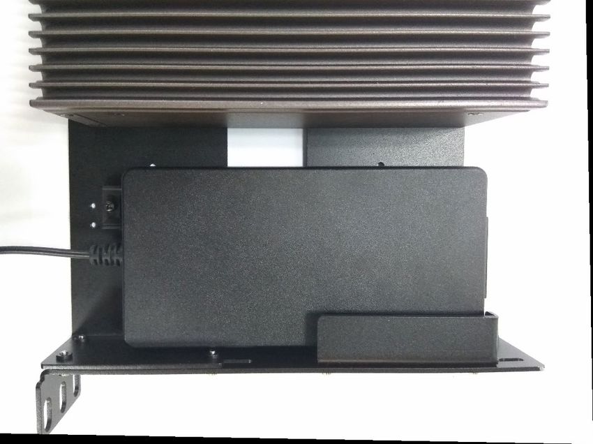
335. Insert the power adapter and lock the adapter bracket(s) onto the shelf using the provided screw(s).
Power Adapter for non POE-supported model:
For the power adapter for the non POE-supported model, please respectively lock a bracket on the front and
the rear shelf, the positions of which are shown in the picture below.
Rear
Front
34Power Adapter for POE-supported model:
For the power adapter for the POE-supported model, please lock only one bracket on the front shelf, the
position of which is shown in the picture below.
355. After the power adapter is firmly secured on the shelf, make sure all the screws on each part are tightly
and securely screwed.
6. Carefully arrange the cable before you install this assembly into the server rack.
Power Adapter for non POE-supported model:
Power Adapter for POE-supported model:
36Appendix 1: Watchdog Timer
A watchdog timer is a hardware component designed to automatically monitor and address system
malfunctions by resetting the processor if issues arise. It operates on a countdown mechanism, starting from a
predetermined value set by the software, and decreasing to zero. The software routinely resets this counter to
prevent it from reaching zero. However, if the counter does hit zero, indicating the software has failed to reset
it, the system assumes a software failure. Consequently, it triggers the processor's reset signal, effectively
rebooting the processor as though a manual power reset was performed by an operator.
To download sample watchdog code, please refer to our official website at www.lannerinc.com.
Reset
Watchdog Timer
Processor
Restart
Clock
37You can also read