INSTALLATION GUIDE - Hilltopper Bikes
←
→
Page content transcription
If your browser does not render page correctly, please read the page content below
INSTALLATION GUIDE
             VER.2021A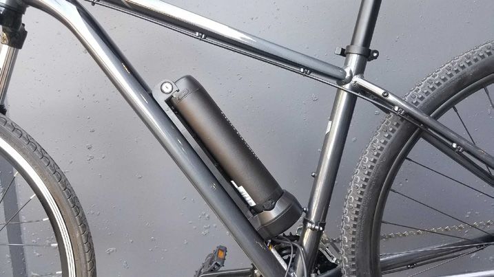
WELCOME TO YOUR HILLTOPPER SPRINTER ELECTRIC BIKE KIT

Congratulations on the purchase of your Hilltopper Sprinter 36V electric bike kit. And welcome to the
Hilltopper community of electric bike enthusiasts.

When unboxing your Sprinter make sure you have all the items listed below as well as an an adjustable
wrench to tighten the axle nuts and a handy pair of scissors.

Included in the kit:

WHEEL W/ HUB MOTOR,TIRE, TUBE, MOUNTING HARDWARE
BATTERY, KEYS, BATTERY DOCK, MOUNTING HARWARE
VARIABLE SPEED THROTTLE
3mm / 4mm ALLEN WRENCH
CHARGER

The install should take around an hour depending on your mechanical skills and enthusiasm.
You can also take your bike and kit to a local bike shop to have them install your kit. Install fees will
vary with different shops.

When you finish your install, double check that all the bolts are tightend, the connections are secured,
the wheel rolls freely, and the battery is charged. Start off slowly at first to get used to the assist.

AND THEN HAVE FUN!
LET’S GET STARTED
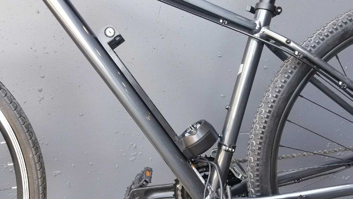
BATTERY
INSTALLING THE BATTERY:
The BATTERY is designed to be mounted to your bike using the water bottle mounts on your bike's frame
NOTE: On the frame is the recommended and generally considered ideal placement.
If your bike does not have a place to mount on the frame then a front or rear bike rack can work.
CAUTION: The BATTERY DOCK must be firmly attached. Make sure to tighten cage bolts periodically.
Any damage to the battery due to insufficient mounting will not be covered under warranty.
STEP 1: Install the BATTERY DOCK on the frame or carrier and use the provided hardware and 4mm Allen
wrench to install.
NOTE: Make sure the base of the cage with the cables points down towards the bottom bracket / pedals.
STEP 2: Insert the BATTERY on to the BATTERY DOCK once it is installed and secured.
CAUTION: You must use the key to lock the battery in place to secure it.
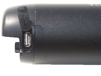
STEP 3: Confirm that the BATTERY is locked and secure before riding. BONUS FEATURE:
The battery has a USB port
STEP 4: To remove the BATTERY from the BATTERY DOCK.
A: Insert Key and turn counter-clockwise.
B: Once unlocked simply pull the BATTERY out of the BATTERY DOCK.
BATTERY DOCK
LOCK
TOP OF BATTERY
TURNING THE BATTERY ON / OFF:
Press the POWER SWITCH on the top of the BATTERY to turn the BATTERY on or off.
The LED BATTERY INDICATOR will turn on.
BLUE = Full battery. GREEN = Partial battery. RED = Empty battery
CAUTION: Make sure to turn the BATTERY off when not in use
to avoid accidental throttle engagement and battery drain. LED BATTERY INDICATOR
POWER SWITCH
CHARGING THE BATTERY:
A. Plug your charger into the wall socket and wait for the charger light to turn GREEN.
B. Plug the charger into the battery. The charger light will turn RED and stay RED while charging.
C. When the charger light turns GREEN your battery is fully charged.
CHARGING PORT
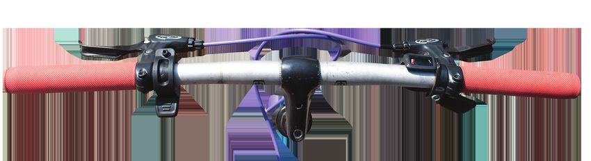
INSTALLING THE VARIABLE SPEED THROTTLE
We recommend putting the VARIABLE SPEED THROTTLE on the LEFT. Placing it after the brake/shifter levers.

          NOTE: You may set up your placement differently depending on your preference and bike set up.

STEP 1: Use the included 3mm hex wrench to loosen the the bolt on the VARIABLE SPEED THROTTLE.

STEP 2: Clasp the VARIABLE SPEED THROTTLE onto the handlebars

STEP 3: Partially tighten the provided bolt on the top of the clamp with the 3mm Allen wrench.

STEP 4: After everything is in place and where you want it TIGHTEN each part to avoid any movement once the bike is in use

         VARIABLE SPEED THROTTLE

CONNECTING THE CABLES:

The Sprinter 36V BATTERY has 2 cable connections.

          IMPORTANT: Be mindful of the arrows on each plug. Align arrows before inserting plugs together.
          Poor installation may result in damaged pins and bad connectivity.

STEP 1: The BATTERY / THROTTLE cable connects the BATTERY to the VARIABLE SPEED THROTTLE

          • Connect the BATTERY cable to the VARIABLE SPEED THROTTLE cable using the yellow connector.
            The yellow connector has a lip that seats inside the connector for better water resistance.

STEP 2: The BATTERY / MOTOR cable (large cable) connects the BATTERY to the MOTOR.

          • Connect the BATERY cable to the MOTOR cable using the BATTERY / MOTOR CONNECTOR .

STEP 3: Secure all your cables with the included zip ties.

          NOTE: Make sure that the cables do not interfere with the steering or hinder the performance of the bike.
                Aligning the cables with your brake and shifter cables is the best way to do this.

                                           BATTERY CABLES                                                              THROTTLE
                                                                                                                      CONNECTOR

                                                  BATTERY / THROTTLE
                                                     CONNECTOR

                                                                                                     BATTERY / MOTOR
                                                                                                       CONNECTOR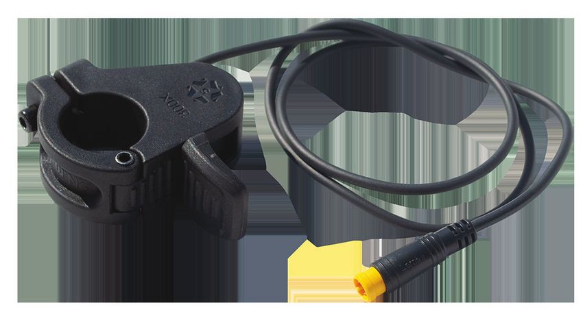
INSTALLING THE HUB MOTOR WHEEL
Please refer to FIG 1 on the following page for installing your new Hilltopper HUB MOTOR WHEEL.

Please orient FIG 1 to your installation position. Installation positions include bike upside down with handlebars and seat resting on
the ground, on a bike rack, or standing with the wheels on the ground. FIG 1 image orientation is looking at the front of the bike with
the wheels on the ground.

The best way to orient FIG 1 is to always use the DRIVE SIDE. This is the side with the chain.

STEP 1: Loosen your brakes and remove your bike’s front wheel.

          DISC BRAKES: After removing your wheel, make sure you put a plastic spacer in between the
                       brake pads to keep them from locking shut.

                    A. Remove the disc brake rotor from your wheel.

                    B. The HUB MOTOR WHEEL is disc brake compatible.

                    C. Align the disc brake rotor with the holes on the MOTOR.

                    D. Attach the rotor to the MOTOR using the disc screws provided.

          NOTE: Your brake may need some adjusting after installation to avoid rubbing.

STEP 2: Slide the THIN WASHER over the axle on both side of the MOTOR.

STEP 3: Slide the TAB WASHER over the axle on both sides of the MOTOR.

          NOTE: Ensure that the MOTOR CABLE is on the DRIVE SIDE of the bike and that the TAB WASHER is properly installed.

          A. The “TAB” on the WASHER faces out from the MOTOR, and down towards the MOTOR CABLE.

          B. The MOTOR CABLE should be below the axle and TAB WASHER, when the bike is standing with the wheels on the ground.

IMPORTANT - INCORRECT TAB WASHER INSTALLATION CAN CAUSE SERIOUS DAMAGE TO THE MOTOR CABLE. THIS IS NOT
COVERED UNDER THE HILLTOPPER WARRANTY.

STEP 4: Set your HUB MOTOR WHEEL in place with the MOTOR CABLE on the DRIVE SIDE.

          Ensure that the bike fork is seated securely on the axle with the fork prongs projecting down
          on either side of the “TAB” of the TAB WASHER.

          Make sure the wheel can turn properly without rubbing or grinding on the fork or brakes.

          NOTE: Remove plastic spacer from disc brakes before setting wheel in place if installed earlier.

STEP 5: Install the rest of the hardware for both sides of the motor

          A. Slide the THICK WASHER over the axle.

          B: Screw the AXLE NUT onto the end of the axle.

STEP 6: Finger tighten each AXLE NUT.

STEP 7: With the bike right side up, push down from the handle bars to ensure the wheel is fully seated in place.
        Then use a wrench to fully tighten the nuts. ( Recommended 38Nm or 28ft-lb).

STEP 8: Slide on each AXLE PROTECTOR CAP.

STEP 9: Reset brakes and make sure the HUB MOTOR WHEEL spins freely.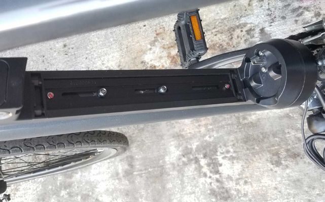
FIG. 1

          THIN                TAB              THICK              AXLE            AXLE
         WASHER             WASHER            WASHER              NUT         PROTECTOR CAP

                                                                                  FORK
                     FORK

                            AXLE                                           AXLE

         DRIVE SIDE
          (CHAIN SIDE)                                                             DISC
                                                                                  BRAKE
                                                                                  ROTOR
                                                                               (IF BIKE HAS
                                                                              DISC BRAKES)

                            MOTOR
                            CABLE                 MOTOR

                                            IMAGE ORIENTATION
                                   LOOKING AT THE FRONT OF THE BIKE WITH
                                        THE WHEELS ON THE GROUND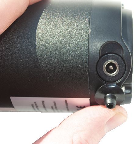
Assumption of Risk, Release of Liability, Indemnity, and Hold Harmless Agreement

By purchasing these Products, I understand and agree to the following:

      Bicycling and related activities are hazardous and injuries are common and ordinary occurrences
       during these activities. I agree to assume all risks of death or injury to any part of the user’s body
       while using the Products.

      &OHDQ5HSXEOLF62'2//&IRUPHUO\GRLQJEXVLQHVVDV&OHDQ5HSXEOLFDQGQRZGRLQJEXVLQHVV
       DV+LOOWRSSHU is not responsible for modifications made by me to my bicycle such as forkfiling or
       anymodifications made to the Products.

      Non-steel and/or non-rigid forks (aluminum, suspension, etc.) are weaker than rigid steel forks.
       &OHDQ5HSXEOLF62'2//&IRUPHUO\GRLQJEXVLQHVVDV&OHDQ5HSXEOLFDQGQRZGRLQJEXVLQHVV
       DV+LOOWRSSHU recommends installation of the Products on rigid steel forks, XQOHVVDQRQVWHHO
       IRUNPRGHOLVVSHFLILFDOO\VXSSOLHGRUFHUWLILHGE\+LOOWRSSHUalthough non-steeland/or non-rigid
       forks areacceptable for use. I agree to assume all risks if I choose installation onnon-steel and/or
       non-rigidforks despite +LOOWRSSHU V recommendation.

      &OHDQ5HSXEOLF62'2//&IRUPHUO\GRLQJEXVLQHVVDV&OHDQ5HSXEOLFDQGQRZGRLQJEXVLQHVV
       DV+LOOWRSSHU recommends tightening the axle nuts with a force of not less than 28 foot-pounds.

      Installing the Products on my bicycle adds additional forces to the bicycle frame and may change
       handling characteristics. Well-adjusted, well-functioning brakes are key to safely using the
       Products and operating any bicycle. I understand and agree that I will have my bicycle’s brakes
       inspected by a bicycle repair shop after installation of the Products.

      To the fullest extent allowed by law, I agree to forever release and hold harmless &OHDQ5HSXEOLF
       62'2//&IRUPHUO\GRLQJEXVLQHVVDV&OHDQ5HSXEOLFDQGQRZGRLQJEXVLQHVVDV+LOOWRSSHUand
       itsowners, agents, employees, and affiliates from any and all responsibility or legal liabilityfor
       anyinjuries, damages or death to any user of any equipment and the Products listed in this
       form,whether resulting from negligence or any other cause. I further agree that I will defend and
       indemnify them if any claim or action is pursued for any injuries, damages or death relating to
       bicycling or any related activities involving the use of this equipment and the Products.

      I accept the Products herein “as is” and with no warranties, express or implied, beyond those
       stated in this agreement and in the manufacturer’s written limited warranty, if any.

      I understand how the Products work and have received instruction and satisfactory answers to
       any questions regarding the use and function of the Products. If this is new equipment, I
       acknowledge receipt of the manufacturer’s written instructions. If at any time the Products do not
       seem to be working properly, I will stop using it immediately andFRQWDFWWKHLUVXSSRUW
       GHSDUWPHQWWR return it for inspection andpossible repair or adjustment.

      If the Products are to be used by someone other than me, I certify that I am acting as agent of the
       user and that I will provide this form and all pertinent warnings and information to the user.

     This document is a legally binding contract which supersedes any other agreements by and
       between the parties, and which constitutes the final and entire agreement regarding the services
       and the Products. This agreement is intended to provide a comprehensive release of all legal
       liability which is binding upon and for the benefit of all parties, their heirs, agents, and assigns, but
       is not intended to assert any claims or defenses that are prohibited by law. If any part of this
       agreement is held to be invalid or unenforceable, the remainder will be given full force and effect.
       This agreement will be interpreted, construed, and governed by and under Washington State law.
       Exclusive venue and jurisdiction over the parties and the subject matter to this agreement will be
       in the Superior Court of Washington in King County.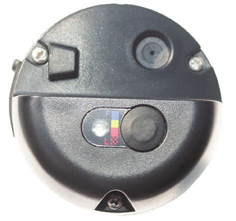
s ale s@hi l l topper bi kes.com
s uppor t @hi l l topper bi kes.com

      225 S LUCILE STREET

  SEATTLE WASHINGTON 98108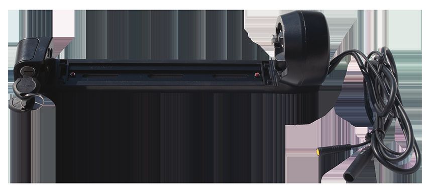
You can also read