Innervated, Self-Sensing Liquid Crystal Elastomer Actuators with Closed Loop Control
←
→
Page content transcription
If your browser does not render page correctly, please read the page content below
Research Article
                                                                                                                                      www.advmat.de

Innervated, Self-Sensing Liquid Crystal Elastomer Actuators
with Closed Loop Control
Arda Kotikian, Javier M. Morales, Aric Lu, Jochen Mueller, Zoey S. Davidson,
J. William Boley,* and Jennifer A. Lewis*

                                                                                                       to program director alignment have been
The programmable assembly of innervated LCE actuators (iLCEs) with pre-                                limited to thin films[14,21] and 1D motifs,[13]
scribed contractile actuation, self-sensing, and closed loop control via core–                         including bulk LCEs with mechanically
shell 3D printing is reported. This extrusion-based direct ink writing method                          induced alignment.[13,22] Recently, extru-
enables coaxial filamentary features composed of pure LM core surrounded                               sion-based 3D printing has been used
by an LCE shell, whose director is aligned along the print path. Specifically,                         to induce director alignment along the
                                                                                                       print path enabling 3D LCEs to be fabri-
the thermal response of the iLCE fiber-type actuators is programmed, meas-                             cated with programmed shape-morphing
ured, and modeled during Joule heating, including quantifying the concomi-                             behavior, actuation response, and seamless
tant changes in fiber length and resistance that arise during simultaneous                             integration with other materials.[23–26] While
heating and self-sensing. Due to their reversible, high-energy actuation and                           shape-morphing behavior has largely been
their resistive feedback, it is also demonstrated that iLCEs can be regulated                          achieved using light-responsive LCEs,[15,17,27]
                                                                                                       thermally responsive LCEs may be optimal
with closed loop control even when perturbed with large bias loads. Finally,
                                                                                                       actuators due to their ability to contract in
iLCE architectures capable of programmed, self-sensing 3D shape change                                 response to embedded stimuli and provide
with closed loop control are fabricated.                                                               sensory feedback.
                                                                                                          Coupling LCEs with resistive elements
                                                                                                       that enable Joule (resistive) heating on
1. Introduction                                                                 demand has already been exploited for locomotion,[28–30] grip-
                                                                                ping,[30,31] and color change.[32,33] However, resistive heating
Liquid crystal elastomers (LCEs) are soft active materials that                 elements are typically laminated onto unidirectionally aligned
are being widely developed for soft robotics,[1–5] actuators,[6–9]              LCE films in bilayer motifs[28,29] limiting their shape, actuation
and shape shifting architectures.[10–12] They are composed of                   mode, and function. Recently, gold serpentine-,[30,34] carbon
a crosslinked polymer network that contains rigid mesogens,                     nanoparticle-,[35] and liquid metal[33,36–38]-based heating ele-
which actuate when heated above their nematic-to-isotropic tran-                ments have been incorporated within LCEs to induce actuation
sition temperature (TNI),[13,14] exposed to light,[15–17] or chemical           upon internally heating these composites above their TNI. The
gradients.[14,18,19] When their mesogen alignment is programmed                 intrinsically soft nature of eutectic gallium indium liquid metal
along a specified direction, known as the director, these active                (LM) elements[39–41] makes this material particularly useful
materials exhibit large, reversible, and anisotropic contraction                for omnidirectional shape shifting, resistive self-sensing, and
with high energy density parallel to the director.[20] Initial methods          closed loop control strategies. Unfortunately, it is challenging
                                                                                to integrate LM within LCE actuators. One emerging strategy
A. Kotikian, A. Lu, Dr. J. Mueller, Dr. Z. S. Davidson, Prof. J. A. Lewis       is to incorporate LM emulsions with LCEs via printing[36,38] or
John A. Paulson School of Engineering and Applied Sciences                      spray-coating.[37] However, sintered, emulsion-based LCE-LMs
and Wyss Institute for Biologically Inspired Engineering                        with complex director alignment lack the self-sensing necessary
Harvard University                                                              for closed loop control,[42] while spray coated LM-LCEs have
Cambridge, MA 02138, USA
E-mail: jalewis@seas.harvard.edu                                                only been demonstrated in the form of unidirectional actuators,
J. M. Morales, Prof. J. W. Boley                                                whose thin LM traces are prone to electrical failure due to elec-
Mechanical Engineering Department                                               tromigration at the high currents required for Joule heating.[37]
Boston University                                                                   Here, we report the programmable assembly of innervated
Boston, MA 02215, USA                                                           LCE actuators (iLCEs) with prescribed contractile actuation,
E-mail: jwboley@bu.edu
                                                                                self-sensing, and closed loop control via core–shell 3D printing.
A. Lu
                                                                                This extrusion-based direct ink writing method enables coaxial
Biological Engineering Division
Draper Laboratory                                                               filamentary features composed of pure LM core surrounded
Cambridge, MA 02139, USA                                                        by an LCE shell, whose director is aligned along the print path
                                                                                (Figure 1). Next, we model, fabricate, and measure the thermal
      The ORCID identification number(s) for the author(s) of this article
      can be found under https://doi.org/10.1002/adma.202101814.
                                                                                response of iLCE fiber-type actuators during Joule heating,
                                                                                including quantifying the concomitant changes in fiber length
DOI: 10.1002/adma.202101814                                                     and resistance that arise during simultaneous heating and

Adv. Mater. 2021, 2101814                                              2101814 (1 of 9)                                        © 2021 Wiley-VCH GmbH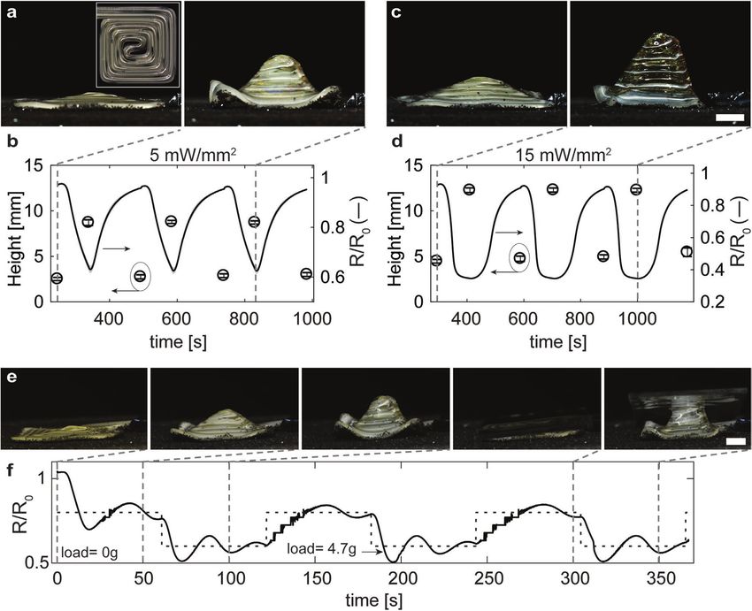
www.advancedsciencenews.com                                                                                                             www.advmat.de

Figure 1. Innervated LCE fibers. a) Schematic illustration of core–shell 3D printing of iLCE fibers composed of a liquid metal (LM) core surrounded
by a liquid crystal elastomer (LCE) shell, whose director is aligned along the print path. b) Schematic illustration of iLCE actuation when cycled above
and below the LCE nematic-to-isotropic transition temperature, TNI. c) Images of an iLCE fiber before (left) and after (right) Joule heating above TNI
(scale bar = 5 mm).

self-sensing. Due to their reversible, high-energy-density actua-             Joule heating, they exhibit a pronounced actuation response
tion and resistive-based sensory feedback, we then show that                  (Figure 1c).
iLCEs can be regulated with closed loop control even when per-                    We can control the actuation behavior of iLCEs by modu-
turbed with large bias loads. Finally, we fabricate iLCE archi-               lating the Joule heating power (Figure 2). Notably, these iLCEs
tectures capable of programmed, self-sensing 3D shape change                  exhibit uniaxial contractile strains comparable to pure 3D
with closed loop control.                                                     printed LCEs reported in our previous work[25] (Figure 2a).
                                                                              We normalize the power input by the initial interfacial area
                                                                              associated with the LM core and LCE shell regions between
2. Results and Discussion                                                     connection leads to enable direct comparison between printed
                                                                              iLCEs, where power input reflects the current input and ini-
To fabricate iLCEs, we co-extrude pure LM and a main-chain                    tial resistance. We then characterized the surface tempera-
LCE ink developed previously[23–25] through a core–shell nozzle               ture of the iLCE fibers at discrete power inputs (Figure 2b
mounted on a custom-built, direct ink writing platform.                       and Figure S2a: Supporting Information). As expected, the
Because alignment of the LCE director to a prescribed print                   center of the iLCE fibers exhibits the highest temperature,
path requires sufficient shear and extension during extrusion,                which increases with power input up to a maximum value
the nozzle shell is retracted relative to the core[43,44] and the             of 178.7 °C ± 4.4% at 40 mW mm–2. Importantly, core–shell
nozzle is tilted 20° from vertical to create a coaxial LCE (shell)-           printing allows iLCE fibers to be produced with relatively large
LM (core) fiber (Figure 1a and Figure S1: Supporting Informa-                 LM cross-sections relative to other patterning methods, ena-
tion). These iLCEs are printed within the nematic phase at                    bling high average current and low maximum voltage inputs
25 °C and subjected to UV curing immediately upon exiting the                 (i.e., 9.28 A ± 5.5% at 0.5315 V ± 6.5%) and consequently ele-
core–shell nozzle to preserve the prescribed director alignment               vated heat generation at attainable maximum current densi-
and the uniformity of LM deposition.[24,25,40,44] The LCE ink is              ties of 29.6 A mm–2 ± 3.3% (40 mW mm–2) without electrical
over-extruded at the beginning and end of the iLCE printing                   failure (Figure S2b, Supporting Information). To predict its
process to locally disrupt director alignment in those regions                thermal behavior, we modeled the thermal response across
thereby facilitating connection to electrical leads with minimal              the cross-sectional area and length of the iLCE fibers. Given
actuation at each end as well as sealing the LM to prevent auto-              their architecture, we expected a minimal temperature gra-
evacuation. When heated above TNI, iLCEs contract in their des-               dient through the cross-section of LCE (Figure 2c) and a mod-
ignated print direction with correlated self-sensing (Figure 1b).             erate heat gradient along the length of the fiber (Figures S3
Since their actuation response is gradual, we define a TNI of                 and S4, Supporting Information). The modeled surface tem-
127 °C as the temperature at which maximum LCE actuation                      perature is in good agreement to experimental maximum sur-
is first observed.[25] When iLCE fibers are heated above TNI via              face temperature (Figure 2d). Resistance decreases with heat

Adv. Mater. 2021, 2101814                                         2101814 (2 of 9)                                              © 2021 Wiley-VCH GmbH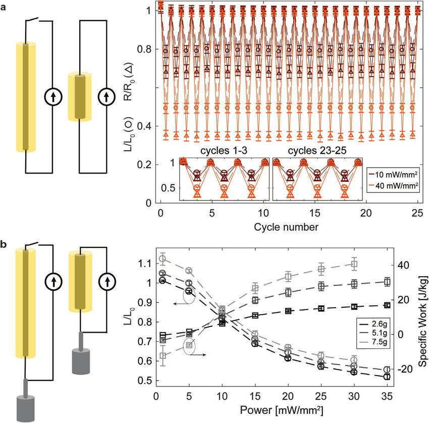
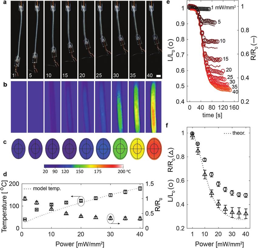
www.advancedsciencenews.com                                                                                                          www.advmat.de

Figure 2. Electrothermal actuation of iLCE fibers. a,b) Optical and corresponding thermal images of representative iLCE fibers actuated with
discrete power inputs ranging from 1–40 mW mm–2, which increase from left to right, as labeled (scale bar = 5 mm). c) Thermal model of the
temperature across the iLCE fiber (cross-section) at these discrete power inputs, where inner and outer black outlines indicate initial dimensions
of LM and LCE, respectively. d) Measured surface temperature, surface temperature extracted from thermal model, and average R/R0 of iLCEs at
these discrete power inputs. e) L/L0 and R/R0 with respect to time of a representative iLCE at these discrete power inputs. f ) Average L/L0, average
R/R0, and theoretical R/R0 modeled with Ohm’s law with resistivity temperature correction for discrete power inputs. [Note: Error bars indicate
standard deviations.]

due to the change in geometry of the actuator, with a plateau               expected, their actuation at different power inputs shows that
in normalized resistance (R/R0) above 25 mW mm–2, also cor-                 R/R0 is closely correlated with normalized length (L/L0) during
responding to the power at which entire iLCE fiber is expected              Joule heating (Figure 2e and Movie S1: Supporting Informa-
to be above its TNI (127 °C) (Figure 2d and Figure S4, Sup-                 tion) and also with cooling (Figure S2c, Supporting Infor-
porting Information).                                                       mation). Hence, changes in L/L0 and R/R0 are dependently
   Next, we investigated the programmable shape change and                  programmable with power input (Figure 2f), i.e., greater con-
predictable self-sensing performance of these iLCE fibers. As               tractile strain results in greater decrease in resistance. Since

Adv. Mater. 2021, 2101814                                        2101814 (3 of 9)                                            © 2021 Wiley-VCH GmbH
www.advancedsciencenews.com www.advmat.de
Figure 3. Performance of iLCE fiber actuators. a) Scheme of reversible iLCE actuation (left) and plot of measured L/L0 and R/R0 when cycled at low
(10 mW mm–2) and high (40 mW mm–2) power inputs (right). b) Scheme of iLCEs lifting weight (left) and plot of measured L/L0 and specific work
(work by LCE mass) when lifting different weights at discrete power inputs (right). [Note: Error bars indicate standard deviations.]
resistance depends on both geometry and temperature, it can Information). Notably, iLCEs demonstrate repeatable pro-
be predicted taking the temperature generated and strain of gramming of L/L0 and resulting R/R0 at both partial and
iLCEs at discrete power inputs (Equation (1)), accounting for full actuation, which are closely correlated throughout the
both the change in geometry and temperature, where α is the duration of the power profile used (Figure S5, Supporting
temperature coefficient of resistivity. Information). Next, we Joule heated iLCEs at several power
inputs and bias loads in weight-lifting experiments. Akin
R L
2
to unstressed iLCE experiments, increasing power input
= [1 + α (T − T0 )] (1) results in larger strains, but decreases with larger bias loads
R0 L0
(Figure 3d). Work exertion increases with both power input
and bias load (Figure 3d). We find that 30 mW mm–2 power
To achieve more reliable changes in L/L0 and R/R0, the cur- and 7.5 g bias load are the maximum power and loading
rent is ramped up and down. However, iLCEs can be rapidly conditions that these iLCEs can reliably lift. Upon heating,
actuated by applying a step input power of 40 mW mm–2, in LCE actuators increase in length prior to contracting with
which over 90% of their maximum contractile strain is attained sufficient bias loads, as observed for other LCEs that are
within 10 s (Figure S2d, Supporting Information). not monodomain (Figure S6, Supporting Information).[24,45]
To characterize actuator performance, we explored iLCE If total contraction results in length greater than the initial
actuation strain repeatability and work output (Figure 3). unbiased length (L0), it is defined as an extension (i.e., L/L0>1)
When cycled between on and off states 25 times, iLCEs and negative work output. Overall, iLCEs lift bias loads over
exhibit average L/L0 = 0.79 ± 0.5% and R/R0 = 0.68 ± 0.7% or 200x their own LCE weight, with maximum specific work
L/L0 = 0.49 ± 0.1% and R/R0 = 0.35 ± 0.9% for low (i.e., (40.7 J kg–1 ± 9.1%) comparable to our prior observations for
10 mW mm–2) and high power (i.e., 40 mW mm–2) on states, pure LCEs.[25] To further increase their work output, cross-
respectively (Figure 3a and Figure S5, Movie S2: Supporting sectional area of the active material can be increased either by
Adv. Mater. 2021, 2101814 2101814 (4 of 9) © 2021 Wiley-VCH GmbH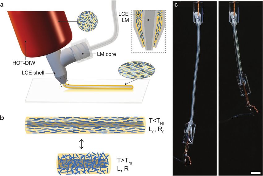
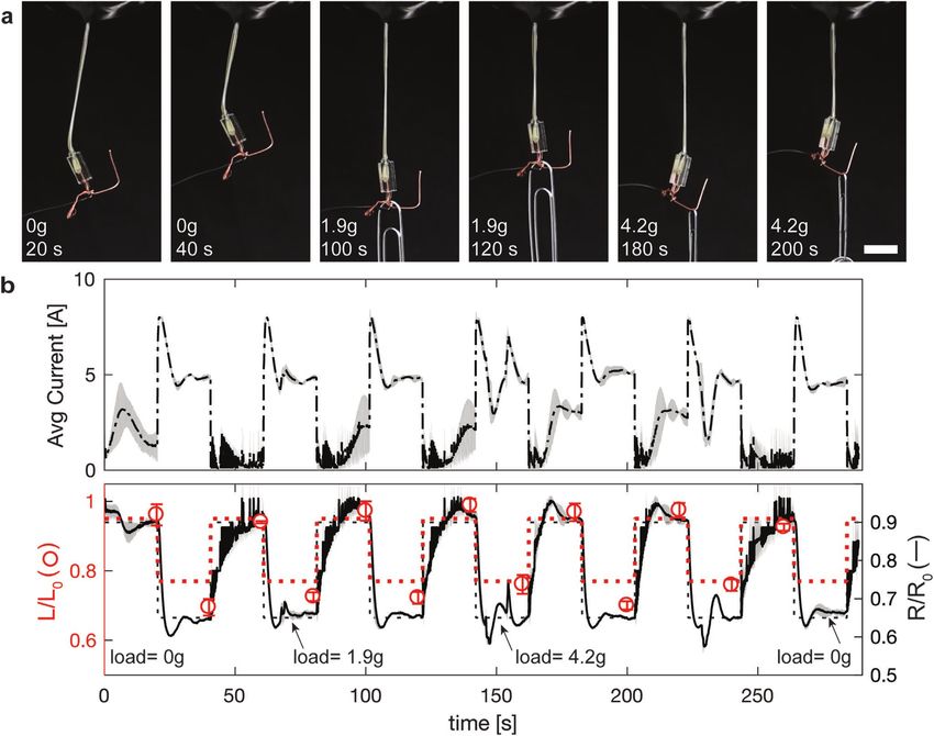
www.advancedsciencenews.com www.advmat.de Figure 4. Closed loop control of iLCE fiber actuation. a) Optical images of a representative iLCE fiber with self-adjusting actuation under several loading conditions (scale bar = 10 mm). b) Self-adjusting current profile (top) and change in resistance and length (bottom) as a function of time for iLCE fibers that are perturbed with bias loads, while reaching target values of resistance (black, dashed) and corresponding length (red, dashed). [Note: Lines denote average values, while shaded regions or error bars indicate standard deviations.] printing bundled iLCE fibers or patterning pure LCEs along- As a final demonstration, we fabricated iLCE spirals with side these fiber(s) via multimaterial 3D printing. 2D director patterning via 3D printing to achieve a program- Given that iLCEs are able to reversibly actuate with self- mable out-of-plane shape change (Figure 5). Specifically, we sensing capabilities and exert substantial work, we explored regu- patterned the iLCE with a square spiral print path, which is lating their actuation response via closed loop control (Figure 4). expected to actuate into a cone when heated above TNI.[14,24] Specifically, a control system is programmed with a target R/R0 Like its fiber actuator counterparts, spiral iLCEs are repeatedly that autoregulates iLCE resistance feedback to reach the target actuated via Joule heating and output a corresponding change over time, even with bias stress perturbations (Figure 4a and in resistance. At low power input (5 mW mm–2), a fraction of Figure S7: Supporting Information). We designate a target resist- the iLCE actuates and forms a partial cone, corresponding to a ance square wave with two targets R/R0 = 0.90 and R/R0 = 0.65 maximum height of 8.77 mm ± 1.9% with corresponding R/R0 for 20 s each, corresponding to target contractile strains of ≈5% of 0.63 ± 2.0% (Figure 5a,b and Movie S4: Supporting Infor- and 23%, respectively. The current rapidly self-adjusts without mation). At higher power input (15 mW mm–2) almost the manual intervention, such that the R/R0 values of the iLCEs lie entire structure is above TNI and actuates into a full cone with a within the target resistance curve with 3.1% and 4.5% overshoot maximum height of 12.29 mm ± 1.6% and corresponding R/R0 and undershoot, respectively. Importantly, our iLCE actuators of 0.35 ± 1.5% (Figure 5c,d and Movie S4: Supporting Informa- are capable of tracking self-sensing actuation while rejecting dis- tion). We note that the frequency of cycling current is slow to turbances up to 4.2 grams (>115x the LCE weight) within 20 s allow cooling of the large structure, with cycles 2–4 shown in (Figure 4b and Figure S7: Supporting Information). Figure 5 (Figure S8, Supporting Information). With sufficient Adv. Mater. 2021, 2101814 2101814 (5 of 9) © 2021 Wiley-VCH GmbH
www.advancedsciencenews.com                                                                                                       www.advmat.de

Figure 5. 3D actuation of iLCE spiral architectures with closed loop control. a) Side-view images of a printed iLCE when cycled between off
(0 mW mm–2, left) and on (5 mW mm–2, right) power input. [A top-view image of the printed iLCE spiral architecture (off state) is shown in the
inset.] b) Average height and resistance profile of printed iLCE spiral architectures cycled at a power input of 5 mW mm–2. c) Side-view images
of a printed iLCE when cycled between off (0 mW mm–2, left) and on (15 mW mm–2, right) power input. d) Average height and resistance profile
as a function of time for printed iLCE spiral architectures cycled at 15 mW mm–2 power. [Note: The plots do not include the first cycle.] e) Image
sequence of a printed iLCE spiral architecture and f ) resistance profile of actuation as a function of time with closed loop control (bottom),
where the target resistance is shown as a dashed line (scale bars = 5 mm). [Note: Lines denote average values, while shaded regions or error bars
indicate standard deviations.]

time to cool, the spiral iLCEs return to a flat shape and within           3. Conclusion
5% of the initial R/R0. The reversible and large change in resist-
ance corresponding to the change in height enables closed loop             We have fabricated innervated LCEs with programmable actua-
control of 3D shape change (Figure 5e,f and Movie S5: Sup-                 tion, self-sensing, and closed loop control via core–shell 3D
porting Information). Here, we program a target resistance                 printing. Importantly, our approach enables pure liquid metal
curve with 60 s intervals at R/R0 = 0.8 and R/R0 = 0.6 and the             cores to be directly embedded within LCE-based coaxial fibers.
iLCE spiral actuates to these targets both with and without a              We demonstrated that these iLCE fibers exhibit prescribed and
bias load (4.7 g). Longer time intervals relative to those of iLCE         predictable thermal responses, strain, and self-sensing upon
fibers are necessary due to the scale of the iLCE spiral and               Joule heating, with strains of nearly 50% when heated above
ensuing timescale of heat dissipation. This capability could               their nematic-to-isotropic transition temperature. Program-
be deployed in the future to create reconfigurable iLCE-based              mability, repeatability, magnitude of sensing signal, and large
antennae with closed loop control, and, hence, tunable RF                  work output enabled closed loop control of printed 1D iLCE
properties.[11]                                                            fibers and 2D-to-3D shape-morphing architectures. With further

Adv. Mater. 2021, 2101814                                       2101814 (6 of 9)                                           © 2021 Wiley-VCH GmbH
www.advancedsciencenews.com www.advmat.de
development, iLCE architectures in arbitrary designs could be Electrothermal Testing: To electrothermally (Joule) heat and measure
printed and controlled in a closed loop system for use in intel- the resistance of iLCE actuators, programmed current was provided via
ligent soft robotics, reconfigurable soft electronics, and RF a power supply (2230G-30-6, Keithley) and voltage was measured at 1 s
intervals using a multimeter (34405A, Agilent) (Figure S10, Supporting
devices. Information). The power source and multimeter were controlled in
parallel by a custom MATLAB script. The resistance R was normalized
by the initial resistance R0 of the iLCE (RM3544-01, HIOKI) to determine
the normalized resistance, R/R0. The length L was normalized to the
4. Experimental Section initial length L0(in pixels) to determine the normalized length, L/L0. The
Materials: The LCE ink is prepared using an aza-Michael addition power input, which was normalized by the total interfacial area between
method, which was reported previously.[25] A 1.1:1 molar ratio of 1,4-bis- the LM (core) and LCE (shell), was calculated from the initial resistance,
[4-(6-acryloyloxy-hexyloxy)benzoyloxy]-2-methylbenzene (Wilshire the LM length between leads, and the elliptical cross-sectional area,
Technologies Inc.) and n-butylamine (Sigma-Aldrich), 0.2 wt% butylated where the major and minor diameters were estimated from imaging the
hydroxy toluene (Fisher Scientific), and 2 wt% Irgacure 651 (BASF) was top and side of the printed core–shell filament (SteREO Discovery V20
combined, stirred, and heated at 105 °C for 18 h in the absence of light. Microscope, Zeiss). The power input of spiral iLCEs was normalized
The ink was transferred to a custom stainless-steel barrel and degassed by the total interfacial area estimated from the initial resistance
in a vacuum oven (VWR) overnight prior to printing. A liquid metal (RM3544-01, HIOKI) and assuming a circular LM cross-section to
(LM) ink composed of eutectic gallium indium (5N Plus) was used account for disparities in cross-sectional area of LM along the edges and
as-received. corners of the spiral.
Core–Shell 3D Printing: Core–shell nozzles were first produced All the electrothermal tests on the iLCE fibers were repeated with
using stereolithography (Perfactory Aureus, Envisiontec) and identical current profiles on the leads replicated without the fiber, which
subsequently coated with 1H,1H,2H,2H-perfluorooctyltriethoxysilane included the compliant lead wire and copper connection lead of the
(FOTS, Oakwood Chemical) to minimize crosslinking with the LCE same lengths. The measured resistance of the leads was subtracted
ink. The nozzle dimensions are provided in Figure S9 (Supporting from the total resistance to obtain the resistance of neat iLCE. All the
Information). The LCE ink was extruded through the outer shell of iLCE fibers were subjected to a current profile that consisted of ramping
the coaxial nozzle by applying pressure (Ultimus V, Nordson EFD). up the current in 0.5 A increments (with 5 s hold at each step) to the
A polyimide flexible heater (McMaster-Carr) was wrapped around peak value required for a given power input (on state), holding in this
the nozzle to maintain a constant temperature of 25 °C. The LM ink state for 60 s, then ramping down the current in 0.5 A increments (with
was extruded through the inner core of the nozzle using a syringe 5 s hold at each step), and, finally, holding the current at 0.5 A for 60 s
pump (PHD Ultra, Harvard Apparatus). During printing, the core– (off state), unless otherwise noted. Cycling experiments were conducted
shell printhead was tilted 20° from the vertical axis to improve using the same current profiles, in which the peak current values were
printability of innervated LM (core)-LCE (shell) architectures, referred held for 30 s. Note, the off resistance of these iLCE fibers was measured
to as iLCEs. These iLCE have ellipsoidal cross-sections, with initial at a current of 0.5 A, i.e., under conditions without significant heat
major and minor diameters of 1.34 ± 0.12 mm × 0.93 ± 0.08 mm and input. Similarly, for spiral iLCEs, an off state was at 0.1 A. Spiral iLCEs
0.702 ± 0.04 mm × 0.571 ± 0.05 mm for the LCE shell and LM core, were tested with 0.1 A per 1 s ramps, and cycled 4× with current holds
respectively. of 60 and 120 s at the on and off states, respectively. Peak on currents
iLCEs were printed in the form of 1D coaxial fibers and 2D-to-3D of 2.813 and 4.873 A were applied for 5 and 15 mW mm–2 power inputs,
shape morphing structures using a custom-built, three-axis motion respectively.
controlled stage (Aerotech Inc.) equipped with on-the-fly UV Finite Element Modeling: The 3D thermal-mechanical model consisted
crosslinking at ≈8 mW cm–2 intensity (Omnicure, S2000). iLCEs fibers of a transient study with solid mechanics and heat transfer modules
and spiral-based planar structures were printed on poly(vinyl alcohol) (Comsol Multiphysics), where the geometry of the device was based on
(80% hydrolized, Aldrich)-coated glass substrates or pre-cleaned glass the average dimensions of the iLCE fiber. The heat source for the model
substrates (VWR), respectively, to allow release from the substrate was set as joule heating through the core of the iLCEs. Heat losses
without deformation. Spiral iLCEs were printed on a rotary stage were assumed to occur by natural convection and a correlation for thin
(Aerotech Inc.), since the tilted nozzle prevents extrusion in both vertical cylinders was implemented to determinate the Nusselt number
positive and negative x-directions. iLCE fibers were typically printed by of the heated surface across space and time.[46] Values for LM thermal
extruding the LCE ink at an applied pressure of 3.6 MPa and the LM conductivity (k = 26.4 W m–1 K–1), specific heat (cp = 333.75 J kg–1 K–1),
ink at a flow rate of 0.0197 mL min–1 with a print speed of 2 mm s–1 density (d = 6250 kg m–3), resistivity (ρ = 2.79 × 10⁻⁷ Ω m), and coefficient
and a print height of 0.25 mm. Spiral iLCEs were printed with a 1.7 mm of thermal expansion (CTE = 32.97 × 10⁻⁶ K–1) and LCE specific heat
center-to-center spacing between filaments under the same conditions, (cp = 1000 J kg–1 K–1) and density (d = 1200 kg m–3) were estimated
except at a reduced print speed of 0.85 mm s–1. At the start and end from the literature.[36,47,48] The LCE thermal conductivity (k), coefficient
of each printed iLCE, the LCE ink was over-extruded by reducing the of thermal expansion (CTE), and mechanical properties (Figure S3,
print speed by a factor of 2 as the nozzle was translated for 5 mm in the Supporting Information) were experimentally measured on printed LCE
desired direction. After printing, the iLCEs were fully crosslinked by an samples, as described below.
additional UV exposure step of ≥30 min in duration on each side (S2000, LCE Characterization: Thermal conductivity (k) was measured with
Omnicure; ≈5 mW cm–2). a thermal conductivity analyzer (CTi, C-Therm) on a printed LCE in
As a final step, a 23 AWG copper wire (Diji-Key Corp.) was a temperature test chamber (TJR-A-F4T, Tenney). To reach thermal
mechanically filed, inserted in the iLCEs, connected to their LM core, equilibrium between measurements, the test chamber was held at
and sealed with an adhesive (NOA 68, Norland Inc.) that promotes target temperatures for 10 min, with measurements taken every 60 s.
bonding upon crosslinking with UV light (S2000, Omnicure; minimum The coefficient of thermal expansion (CTE) was measured via a
300 s). A 28 AWG compliant lead wire (Diji-Key Corp.) of roughly 10 cm dilatometer (DiL, C-Therm) both parallel and perpendicular to the
length was then soldered onto one end of iLCE fibers as to not affect director of printed LCEs with approximate dimensions of 5 × 5 × 2 mm3
LCE L/L0 and R/R0 (Figure S10, Supporting Information). Spiral iLCEs with a heating rate of 2 °C min–1. The data were processed using the
did not require a lead wire. During their 2D-to-3D shape morphing, ASTM E0229-17 standard. Mechanical testing was conducted on
these architectures were imaged on a layer of black craft sand (Just printed LCE perpendicular bilayers with approximate dimension
Artifacts) on super-cushioning polyurethane foam (McMaster-Carr) to of 30 × 5 × 0.4 mm3 (Instron 5566, 100 N load cell). The mechanical
minimize friction, adhesion, and thermal diffusion with the substrate deformation was modeled by the 5-parameters hyperelastic Mooney–
upon cooling. Rivlin Model,[49] where appropriate parameters for the mechanical model
Adv. Mater. 2021, 2101814 2101814 (7 of 9) © 2021 Wiley-VCH GmbHwww.advancedsciencenews.com www.advmat.de
were determined by optimization via the Levenberg–Marquardt method Data Availability Statement
(Figure S3, Supporting Information).
Actuation Characterization: Images used to measure length were The data that support the findings of this study are available from the
captured (EOS Rebel T2i, Canon) every 5 s for iLCE fibers and every 1 s corresponding author upon reasonable request.
for spiral iLCEs and analyzed using image analysis software (Fiji) and a
custom Python script. The iLCE actuators used for thermal imaging were
first spray painted with a thin coat of graphite paint (Bonderite L-GP G
Acheson) to prevent errors in surface temperature measurement arising Keywords
from the nematic to isotropic phase transition. Thermal imaging was
3D printing, liquid crystal elastomers, actuators, shape morphing
carried out using an IR camera (SC5000, FLIR) and their temperature
was calculated (Altair) using an emissivity of 0.95. The thermal images,
Received: March 7, 2021
provided in Figure 2b, correspond to the end of the peak current time for
Revised: April 1, 2021
the on state of each condition.
Published online:
Average values of normalized resistance, normalized length, and work
for each printed iLCE fiber tested were averaged over the second half of
peak current input (e.g., for a peak hold of 60 s, the measured values
at 30–60 s would be averaged). Bias load was applied to the actuators
by adding paperclips to the bottom of the actuator. Weight-lifting [1] D. Rus, M. T. Tolley, Nature 2015, 521, 467.
experiments were conducted starting at low power then increasing to [2] T. J. Wallin, J. Pikul, R. F. Shepherd, Nat. Rev. Mater. 2018, 3, 84.
high power for each load and actuating at 35 mW mm–2 without weight [3] S. W. Ula, N. A. Traugutt, R. H. Volpe, R. R. Patel, K. Yu,
between loads to erase the thermal history. Specific work was calculated C. M. Yakacki, Liq. Cryst. Rev. 2018, 6, 78.
with respect to the average mass of LCE (35 mg ± 2 mg), estimated [4] M. Wehner, R. L. Truby, D. J. Fitzgerald, B. Mosadegh,
from the cross-sectional dimensions across 50 mm of fiber and taking G. M. Whitesides, J. A. Lewis, R. J. Wood, Nature 2016, 536, 451.
the density of LCE as 1.08 g mL–1. The average height of spiral iLCEs was [5] Y. Y. Xiao, Z. C. Jiang, X. Tong, Y. Zhao, Adv. Mater. 2019, 31,
acquired at the end of the peak current time for on and off states. 1903452.
Closed Loop Control: The PID closed loop control was implemented [6] J. M. McCracken, B. R. Donovan, T. J. White, Adv. Mater. 2020, 32,
using a custom script (Python 2.7) to program electrical current 1906564.
and measure the voltage drop across the iLCEs (E36233a, Keysight). [7] L. Hines, K. Petersen, G. Z. Lum, M. Sitti, Adv. Mater. 2017, 29,
The target R/R0 was inputted in the control script and the target L/L0
1603483.
estimated given the target R/R0 and the electrothermal actuation
[8] C. Ohm, M. Brehmer, R. Zentel, Adv. Mater. 2010, 22, 3366.
characterization (Figure 2f). The sampling rate of the loop was set to be
[9] J. Liu, Y. Gao, H. Wang, R. Poling-Skutvik, C. O. Osuji, S. Yang, Adv.
1000 Hz, which is 4 orders of magnitude faster than the thermal response
of the iLCE. PID gains were estimated using the system identification Intell. Syst. 2020, 2, 1900163.
toolbox (MATLAB). For iLCE fibers, the PID gains (Kp, Kd, and Ki) were [10] X. Kuang, D. J. Roach, J. Wu, C. M. Hamel, Z. Ding, T. Wang,
found to be 22, 21, and 0.9 respectively. For the spiral iLCEs, the PID M. L. Dunn, H. J. Qi, Adv. Funct. Mater. 2018, 29, 1805290.
gains (Kp, Kd, and Ki) were found to be 2.5, 2, and 0.001 respectively. The [11] J. W. Boley, W. M. Van Rees, C. Lissandrello, M. N. Horenstein,
target step lengths of iLCE fibers and spiral architecture were 20 and 60 s, R. L. Truby, A. Kotikian, J. A. Lewis, L. Mahadevan, Proc. Natl. Acad.
respectively. Images used to measure length of the control response Sci. USA 2019, 116, 20856.
were captured (Nikon D850) every 2 s for iLCE fibers and every 1 s for [12] K. Bertoldi, V. Vitelli, J. Christensen, M. Van Hecke, Nat. Rev. Mater.
spiral iLCEs and analyzed for length using image analysis software (After 2017, 2, 17066.
Effects, Adobe) and a custom Python script. [13] J. Kupfer, H. Finkelmann, Makromol. Chem., Rapid Commun. 1991,
12, 717.
[14] T. H. Ware, M. E. McConney, J. J. Wie, V. P. Tondiglia, T. J. White,
Science (80-.). 2015, 347, 982.
Supporting Information [15] A. W. Hauser, D. Liu, K. C. Bryson, R. C. Hayward, D. J. Broer, Mac-
romolecules 2016, 49, 1575.
Supporting Information is available from the Wiley Online Library or
from the author. [16] Y. Yu, M. Nakano, T. Ikeda, Nature 2003, 425, 145.
[17] S. Palagi, A. G. Mark, S. Y. Reigh, K. Melde, T. Qiu, H. Zeng,
C. Parmeggiani, D. Martella, A. Sanchez-Castillo, N. Kapernaum,
F. Giesselmann, D. S. Wiersma, E. Lauga, P. Fischer, Nat. Mater.
Acknowledgements 2016, 15, 647.
[18] K. D. Harris, C. W. M. Bastiaansen, D. J. Broer, J. Microelectromech.
The authors gratefully acknowledge support from the National Science Syst. 2007, 16, 480.
Foundation through the Harvard MRSEC (DMR-2011754; A.K., J.L.), the [19] J. M. Boothby, H. Kim, T. H. Ware, Sens. Actuators, B 2017, 240,
ARO MURI (W911NF-17-1-03; Z.D., J.L.), NSF DMREF (DMR-1922321; 511.
J.M., J.L), and the AFOSR Young Investigator Award (FA9550-20-1-0365; [20] T. J. White, D. J. Broer, Nat. Mater. 2015, 14, 1087.
J.W.B., J.M.M.). A.L. gratefully acknowledges support provided by a [21] H. Aharoni, Y. Xia, X. Zhang, R. D. Kamien, S. Yang, Proc. Natl.
Draper Lab fellowship. This work made use of the Shared Experimental
Acad. Sci. USA 2018, 115, 7206.
Facilities supported in part by the Harvard MRSEC. The authors thank
[22] C. M. Yakacki, M. Saed, D. P. Nair, T. Gong, S. M. Reed,
E. Guzman, S.C. Slimmer, N. Larson, J. P. S. Aquino, S. F. Zopf, and M.
C. N. Bowman, RSC Adv. 2015, 5, 18997.
Horenstein for helpful discussions, J. Alvarenga for technical assistance,
and L.K. Sanders for assistance with videography. [23] C. Ambulo, J. J. Burroughs, J. M. Boothby, H. Kim, M. R. Shankar,
T. H. Ware, ACS Appl. Mater. Interfaces 2017, 9, 37332.
[24] A. Kotikian, R. L. Truby, J. W. Boley, T. J. White, J. A. Lewis, Adv.
Mater. 2018, 30, 1706164.
Conflict of Interest [25] A. Kotikian, C. Mcmahan, E. C. Davidson, J. M. Muhammad,
R. D. Weeks, C. Daraio, J. A. Lewis, Sci. Robot. 2019, 4,
The authors declare no conflict of interest. eaax7044.
Adv. Mater. 2021, 2101814 2101814 (8 of 9) © 2021 Wiley-VCH GmbHwww.advancedsciencenews.com www.advmat.de
[26] M. O. Saed, C. P. Ambulo, H. Kim, R. De, V. Raval, K. Searles, [37] T. A. Kent, M. J. Ford, E. J. Markvicka, C. Majidi, Multifunct. Mater.
D. A. Siddiqui, J. M. Cue, D. C. Rodrigues, M. C. Stefan, R. Shankar, 2020, 3, 025003.
T. H. Ware, Adv. Funct. Mater. 2019, 29, 1806412. [38] C. P. Ambulo, M. J. Ford, K. Searles, C. Majidi, T. H. Ware, ACS
[27] A. H. Gelebart, D. Jan Mulder, M. Varga, A. Konya, G. Vantomme, Appl. Mater. Interfaces 2020, 13, 12805.
E. W. Meijer, R. L. B. Selinger, D. J. Broer, Nature 2017, 546, 632. [39] M. D. Dickey, R. C. Chiechi, R. J. Larsen, E. A. Weiss, D. A. Weitz,
[28] C. Yuan, D. J. Roach, C. K. Dunn, Q. Mu, X. Kuang, C. M. Yakacki, G. M. Whitesides, Adv. Funct. Mater. 2008, 18, 1097.
T. J. Wang, K. Yu, H. J. Qi, Soft Matter 2017, 13, 5558. [40] T. V. Neumann, M. D. Dickey, Adv. Mater. Technol. 2020, 5,
[29] C. Wang, K. Sim, J. Chen, H. Kim, Z. Rao, Y. Li, W. Chen, J. Song, 2000070.
R. Verduzco, C. Yu, Adv. Mater. 2018, 30, 1706695. [41] L. Yu, J. C. Yeo, R. H. Soon, T. Yeo, H. H. Lee, C. T. Lim, ACS Appl.
[30] Q. He, Z. Wang, Y. Wang, A. Minori, M. T. Tolley, S. Cai, Sci. Adv. Mater. Interfaces 2018, 10, 12773.
2019, 5, eaax5746. [42] E. J. Markvicka, M. D. Bartlett, X. Huang, C. Majidi, Nat. Mater.
[31] D. J. Roach, X. Kuang, C. Yuan, K. Chen, H. J. Qi, Smart Mater. 2018, 17, 618.
Struct. 2018, 27, 125011. [43] M. A. H. Khondoker, A. Ostashek, D. Sameoto, Adv. Eng. Mater.
[32] Y. Jiang, D. Xu, X. Li, C. Lin, W. Li, Q. An, C. Tao, H. Tang, G. Li, 2019, 21, 1900060.
J. Mater. Chem. 2012, 22, 11943. [44] K. Wu, P. Zhang, F. Li, C. Guo, Z. Wu, Polymers (Basel) 2018, 10,
[33] B. Ma, C. Xu, L. Cui, C. Zhao, H. Liu, ACS Appl. Mater. Interfaces 330.
2021, 13, 5574. [45] M. O. Saed, A. H. Torbati, C. A. Starr, R. Visvanathan, N. A. Clark,
[34] J. M. Boothby, J. C. Gagnon, E. Mcdowell, T. Van Volkenburg, C. M. Yakacki, J. Polym. Sci., Part B: Polym. Phys. 2017, 55, 157.
L. Currano, Z. Xia, Soft Rob. 2021, https://doi.org/10.1089/ [46] A. Bejan, Convection Heat Transfer, John Wiley & Sons, Hoboken,
soro.2020.0135. NJ, USA 2013.
[35] M. Chambers, H. Finkelmann, M. Remškar, A. Sánchez-Ferrer, [47] M. D. Bartlett, N. Kazem, M. J. Powell-palm, X. Huang, W. Sun,
B. Zalar, S. Žumer, J. Mater. Chem. 2009, 19, 1524. Proc. Natl. Acad. Sci. USA 2017, 114, 2143.
[36] M. J. Ford, C. P. Ambulo, T. A. Kent, E. J. Markvicka, C. Pan, [48] S. Liu, M. C. Yuen, E. L. White, J. W. Boley, B. Deng, G. J. Cheng,
J. Malen, T. H. Ware, C. Majidi, Proc. Natl. Acad. Sci. USA 2019, 116, R. Kramer-Bottiglio, ACS Appl. Mater. Interfaces 2018, 10, 28232.
21438. [49] N. Kumar, V. V. Rao, MIT Int. J. Mech. Eng. 2016, 6, 43.
Adv. Mater. 2021, 2101814 2101814 (9 of 9) © 2021 Wiley-VCH GmbHYou can also read