HPE NIMBLE STORAGE AND HPE ALLETRA 6000 PEER PERSISTENCE - Deployment considerations for NimbleOS 5.1 and later
←
→
Page content transcription
If your browser does not render page correctly, please read the page content below
Technical white paper

                                                   Check if the document is available
                                                   in the language of your choice.

HPE NIMBLE STORAGE AND
HPE ALLETRA 6000 PEER PERSISTENCE
Deployment considerations for NimbleOS 5.1 and later
Technical white paper

CONTENTS
Executive summary.............................................................................................................................................................................................................................................................................................................. 3
Synchronous replication on HPE Nimble Storage and HPE Alletra 6000 arrays....................................................................................................................................................... 3
     Array groups ........................................................................................................................................................................................................................................................................................................................ 4
     Volume collections ......................................................................................................................................................................................................................................................................................................... 5
Other Peer Persistence components ................................................................................................................................................................................................................................................................... 5
     Witness...................................................................................................................................................................................................................................................................................................................................... 5
     Automatic failover ........................................................................................................................................................................................................................................................................................................... 5
     Automatic switchover .................................................................................................................................................................................................................................................................................................. 6
Infrastructure requirements ......................................................................................................................................................................................................................................................................................... 6
     Supported HPE Nimble Storage arrays ...................................................................................................................................................................................................................................................... 6
     Supported operating systems.............................................................................................................................................................................................................................................................................. 7
NimbleOS 5.1.x features .................................................................................................................................................................................................................................................................................................. 7
     Multiprotocol access to an array ....................................................................................................................................................................................................................................................................... 7
     Group scoped target iSCSI volumes ............................................................................................................................................................................................................................................................... 7
     Support for synchronous replication ............................................................................................................................................................................................................................................................. 8
Network requirements and considerations .................................................................................................................................................................................................................................................... 9
Summary of Peer Persistence failure handling ........................................................................................................................................................................................................................................11
Peer Persistence combined with asynchronous snapshot replication ...............................................................................................................................................................................12
Installation and setup procedures .......................................................................................................................................................................................................................................................................12
     Installing and configuring the Witness......................................................................................................................................................................................................................................................12
     Configuring the host ..................................................................................................................................................................................................................................................................................................22
     Setting up the Initial array configuration ................................................................................................................................................................................................................................................22
     Adding the second array .......................................................................................................................................................................................................................................................................................25
     Setting up ASO ...............................................................................................................................................................................................................................................................................................................28
     Important CLI steps ....................................................................................................................................................................................................................................................................................................29
     Configuring synchronously replicated volumes ...............................................................................................................................................................................................................................30
     Validating synchronous replication setup..............................................................................................................................................................................................................................................40
Automatic or manual switchover ..........................................................................................................................................................................................................................................................................42
     Manual failover/switchover when the GL fails ...................................................................................................................................................................................................................................42
     Manual failover/switchover when the BGL fails................................................................................................................................................................................................................................51
     Advantages of using ASO versus manual handover....................................................................................................................................................................................................................59
Restoring active paths for volumes after recovering from an ASO.......................................................................................................................................................................................59
Conditions that block ASO .........................................................................................................................................................................................................................................................................................59
     Unavailable Witness ...................................................................................................................................................................................................................................................................................................59
     Volume collection out of sync ...........................................................................................................................................................................................................................................................................60
Testing Peer Persistence functionality ...........................................................................................................................................................................................................................................................61
     Test Witness failure or disconnect ...............................................................................................................................................................................................................................................................61
     Test failure or failover of the array’s local controller ....................................................................................................................................................................................................................65
     Test failure of a single replication link .......................................................................................................................................................................................................................................................67
     Test failure of all replication links ..................................................................................................................................................................................................................................................................69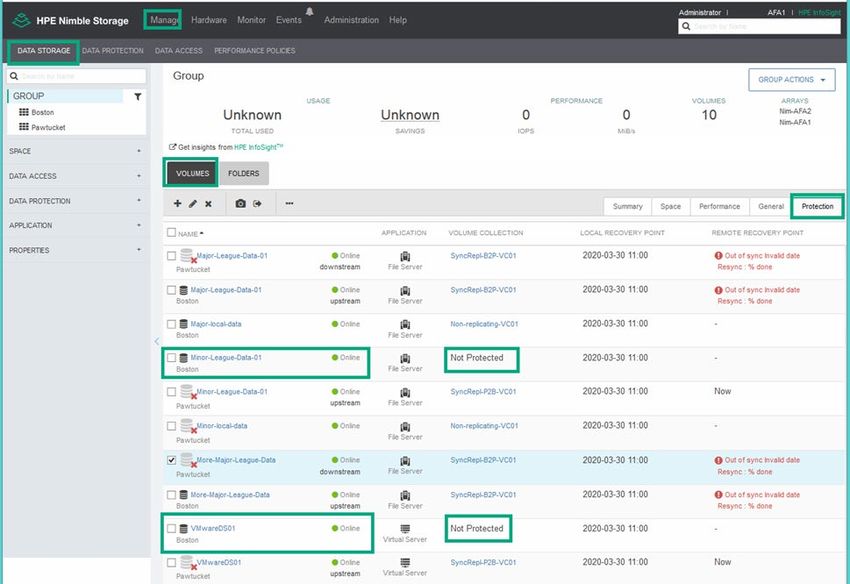
Technical white paper

      Test array failure ...........................................................................................................................................................................................................................................................................................................72
Upgrading the Witness ..................................................................................................................................................................................................................................................................................................81
      Upgrade current Witness server.....................................................................................................................................................................................................................................................................81
      Replace current Witness server VM with new server VM from the updated Witness OVA package..............................................................................................81
Changing network settings for Witness VM deployed through OVA package ..........................................................................................................................................................83
Detailed cabling diagram .............................................................................................................................................................................................................................................................................................84
Checklist ......................................................................................................................................................................................................................................................................................................................................85
Limitations and exclusions .........................................................................................................................................................................................................................................................................................85
Summary .....................................................................................................................................................................................................................................................................................................................................86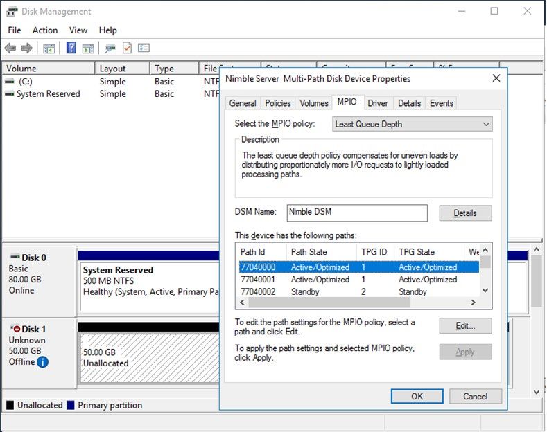
Technical white paper                                                                                                                 Page 3

EXECUTIVE SUMMARY
The HPE Nimble Storage and HPE Alletra 6000 Peer Persistence feature is designed for applications that require zero to near-zero recovery
point objectives (RPO) and recovery time objectives (RTO). By using multisite synchronous replication with automatic switchover (ASO),
Peer Persistence enables business continuity, keeping your applications online all of the time. This technical paper explains basic concepts of
Peer Persistence and describes networking requirements and recommendations. It also shows how to deploy host toolkits and the Witness
software to automate the switchover to synchronously replicated volumes and how to configure HPE Nimble Storage and
HPE Alletra 6000 arrays to create and access synchronously replicated volumes.
Target audience: The target audience for this paper includes storage administrators and systems integrators who are planning to deploy
HPE Nimble Storage or HPE Alletra 6000 Peer Persistence in their data centers.
Document purpose: This document describes the building blocks and basic configuration required to deploy Peer Persistence with
HPE Nimble Storage arrays or HPE Alletra 6000 arrays and explains some of the methodology that is needed to test the ASO functionality.
For more information, including detailed administration guides, see the documentation page on the HPE InfoSight portal.

SYNCHRONOUS REPLICATION ON HPE NIMBLE STORAGE AND HPE ALLETRA 6000
ARRAYS
Synchronous replication is a business continuity solution that uses LAN or WAN technologies to mirror data between sites, ensuring the
existence of multiple copies of guaranteed up-to-date information. Synchronous replication provides protection from array, environment, or
site failures with no data loss because all I/O is mirrored across sites with a true RPO of zero—an achievement that is neither available nor
possible with periodic snapshot-based replication. To understand how to deploy Peer Persistence with HPE Nimble Storage and HPE Alletra
6000 arrays, it helps to understand how synchronous replication is implemented in NimbleOS 5.1.x.
All HPE Nimble Storage and HPE Alletra 6000 arrays have two controllers, one active and one standby. As Figure 1 shows, when an initiator
writes data to a volume on the array, the data lands in non-volatile random-access memory (NVRAM) on the active controller and is
immediately replicated across a chassis backplane to the NVRAM in the standby controller. The array waits until the data is successfully
mirrored to the NVRAM in the standby controller before it acknowledges to the initiator that the data has been written.

FIGURE 1. Flow of data during write operation to HPE Nimble Storage array (cabling omitted for standby controller)
Technical white paper                                                                                                                      Page 4

For synchronous replication, HPE Nimble Storage and HPE Alletra 6000 arrays extend the number of copies of data that are written before
the write operation is acknowledged to the initiator. If an initiator writes data to a volume that is configured for synchronous replication, the
data lands in the NVRAM of the active controller on the array that is presenting the volume to the initiator. Next, the data is mirrored across
the chassis backplane to the standby controller in the same array, and then it is copied across an IP address interface to the active controller
in the second array. Finally, the data is mirrored across the second array’s backplane into the NVRAM on the second array’s standby
controller. Only after the data is successfully copied to all of these locations does the first array acknowledge to the initiator that the data has
been written. Figure 2 shows the data paths that are used for synchronous replication.

FIGURE 2. Data paths for synchronous replication (cabling omitted for standby controllers)

NOTE
The Peer Persistence feature requires uniform access to the arrays from all hosts, meaning that hosts on both sites must have access to the
arrays on both sites so that data paths can move nondisruptively from one array to the other in the case of a failure. Non-uniform access, in
which hosts can access only the arrays on the same site, is not supported.

Array groups
Every HPE Nimble Storage or HPE Alletra 6000 array belongs to an array group, even if the group consists of a single array. As more arrays
are added to the group, the first array becomes the group leader (GL), and all of the arrays are managed as a single entity through the GL’s
management IP address. The GL maintains all configuration data for all arrays in the group.
Beginning with NimbleOS 5.1.x, the role of backup group leader (BGL) has been defined. This role can be assigned to one of the arrays in
the group. All of the group configuration data is mirrored between the GL and the BGL, and it is easy in NimbleOS 5.1.x to migrate the GL
role to the BGL array.
Technical white paper                                                                                                                 Page 5

Because of the new BGL role, it is important to include a secondary management IP address in the array group’s network configuration.
The secondary management IP address can be used to open an SSH session with the BGL array, but it cannot provide GUI access to the
array group or the BGL. If the BGL array assumes the role of GL, it becomes inaccessible through the secondary management IP address. As
soon as an array is designated as the GL, access to that array shifts to the primary management IP address. The secondary management IP
address can be used to access the new BGL array through the CLI—if and when it comes online.
In general, an array group can consist of up to four HPE Nimble Storage or HPE Alletra 6000 arrays; however, for synchronous replication
configurations, the maximum (and minimum) group size is two arrays. When multiple arrays are configured in the same array group,
NimbleOS makes it possible for each array to have a separate storage pool or for storage pools to include multiple arrays. In a synchronous
replication configuration, however, all arrays in the array group must be in separate storage pools.

Volume collections
In the HPE Nimble Storage and HPE Alletra 6000 array operating system, volume collections are groups of volumes that have the same
data protection requirements (such as snapshot consistency, frequency, and retention) and the same replication rules. Volumes are
designated for synchronous replication at the volume collection level. A volume collection can be set up to synchronously replicate all of the
volumes it contains to the partner pool in the array group.
All volumes in a given volume collection are synchronously replicated, but not all synchronously replicated volumes are required to be in the
same volume collection. For example, several volumes that host Microsoft® SQL Server databases have certain data protection requirements
that differ from the requirements of a set of volumes used for VMware® data stores. The two sets of volumes can be placed in separate
volume collections, with both volume collections configured for synchronous replication.
Another reason to split volumes into different volume collections is to enable each of the two storage pools in the group to be the source
pool for some of the synchronously replicated volumes and the destination pool for others. When a volume collection is configured for
synchronous replication, the pool that is designated as the replication partner becomes the destination pool, making the other pool the
source.

OTHER PEER PERSISTENCE COMPONENTS
HPE Nimble Storage and HPE Alletra 6000 Peer Persistence is built on top of the synchronous replication functionality that was
introduced in NimbleOS 5.1.x. Synchronous replication allows exact copies of volumes to be kept on two arrays that are joined in a group.
With HPE Nimble Storage and HPE Alletra 6000 synchronous replication, only one of the arrays hosts an active path to any given volume,
but if one of the two arrays becomes unavailable, the active path for all synchronously replicated volumes can be moved to the other array.
Peer Persistence, available with NimbleOS 5.2.x, provides the mechanisms for two additional capabilities:
• To automate the migration of the GL duties to the BGL, if necessary
• To seamlessly switch the active path from one array to the other

Witness
In the context of Peer Persistence, the Witness is a service that is installed on an independent server—ideally, in a different failure domain
from either of the two arrays. The server on which the Witness is installed can be a virtual machine (VM) or a physical server, and the round-
trip time (RTT) between the Witness and each array must be 250 milliseconds or less. The ability of each array to communicate with the
Witness serves as a factor in determining whether an ASO should take place.
By default, TCP/IP port 5395 is used for the communication between the arrays and the Witness, but this port is configurable based on the
requirements of the environment. For the Witness software and the latest requirements for the server on which it is installed, go to the
HPE InfoSight portal.

Automatic failover
HPE Nimble Storage automatic failover (AFO) is the failing over of the group management services from the GL to the BGL. This action
occurs as a precursor to a Peer Persistence ASO if the GL array becomes unreachable. After an AFO, the newly promoted GL becomes
accessible from the array group’s primary management IP address, and any SSH session to the former BGL that uses the array group’s
secondary management IP address is terminated. When the former GL becomes available, it functions as the BGL and becomes accessible
through SSH at the secondary management IP address.
Technical white paper                                                                                                                  Page 6

Automatic switchover
The HPE Nimble Storage and HPE Alletra 6000 automatic switchover (ASO) feature can be used with synchronous replication to enable
fully automatic failure recovery. ASO currently works on multiarray groups that consist of a maximum of two arrays. When ASO is enabled
and a switchover occurs, the destination array that serves as the mirror for a volume collection is switched automatically, and application I/O
is redirected to the partner without host-side reconfiguration.
ASO facilitates automatic failure recovery through the use of a tie-breaker Witness service that must be installed on an independent server.
Details about the Witness’s server must be configured on the array group. ASO is enabled by default if the Witness has been configured on
the array group and the Witness is reachable from the array group. If ASO is not desired, take one of the following actions:
• Remove the Witness configuration from the array group.
• Disable the Witness service on its host server or power off the Witness server.
• In an SSH session, issue the CLI command group --edit --auto_switchover_enabled no.

NOTE
If the Witness information has not been supplied to the array group, then the act of enabling ASO does not actually cause ASO to turn on.

INFRASTRUCTURE REQUIREMENTS
HPE Nimble Storage and HPE Alletra 6000 Peer Persistence has requirements for specific arrays and operating systems.

Supported HPE Nimble Storage arrays
Peer Persistence is supported on all HPE Alletra 6000 array models and all current HPE Nimble Storage array models except for the
HF20H. The feature is also supported on all previous-generation array models except for the CS1000H, SF100, and SF300.
The two arrays that are configured for Peer Persistence must be of the same model, but they can have different capacities and networking
options installed. For example, you might group two HPE Nimble Storage AF40 arrays for the purpose of using the Peer Persistence feature.
One array might have a capacity of 11 TB and four 16 Gb FC ports configured, and the second array might have a capacity of 23 TB and
eight 16 Gb FC ports.
Note that capacity differences between the two arrays (especially different flash cache sizes in Adaptive Flash arrays) might result in
performance discrepancies for application servers as the active path to volumes moves from one array to another. The same can be said for
differences in the host adapter/network interface card configurations in the two arrays: that is, their performance might differ if host
connectivity has a wider or a narrower pipe. Table 1 lists the HPE Nimble Storage array models that support or do not support
Peer Persistence.
TABLE 1. Current HPE Nimble Storage array support for Peer Persistence
HPE Nimble Storage array                                Peer persistence supported?

AF20                                                    Yes
AF20Q                                                   Yes
AF40                                                    Yes
AF60                                                    Yes
AF80                                                    Yes
HF20                                                    Yes
HF20H                                                   No
HF20C                                                   Yes
HF40                                                    Yes
HF40C                                                   Yes
HF60                                                    Yes
HF60C                                                   Yes
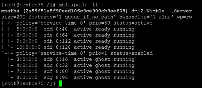
Technical white paper                                                                                                               Page 7

Table 2 lists the legacy array models that support or do not support Peer Persistence.
TABLE 2. Legacy HPE Nimble Storage array support for Peer Persistence
HPE Nimble Storage array                                Peer persistence supported?

AF1000                                                  Yes
AF3000                                                  Yes
AF5000                                                  Yes
AF7000                                                  Yes
AF9000                                                  Yes
CS1000                                                  Yes
CS1000H                                                 No
CS3000                                                  Yes
CS5000                                                  Yes
CS7000                                                  Yes
SF100                                                   No
SF300                                                   No

Supported operating systems
The HPE Storage Connection Manager (NCM) manages connections from the host to volumes on HPE Alletra 6000 and HPE Nimble
Storage arrays and simplifies the process of configuring multiple connections and multipath I/O (MPIO) settings. The HPE Storage host-side
toolkits also set critical timeout values that are necessary for performing failover operations.

IMPORTANT
Installation of the proper toolkit is required for Peer Persistence deployment.

NIMBLEOS 5.1.X FEATURES
NimbleOS version 5.1.x introduces many new features for HPE Nimble Storage arrays. For a complete list of these features, see the
NimbleOS Release Notes in the HPE InfoSight portal. This version of NimbleOS introduces three features in particular that must be
considered when deploying Peer Persistence (note that the minimum OS version for HPE Alletra 6000 arrays is 6.0.0):
• Multiprotocol access to an array
• Group scoped target (GST) iSCSI volumes
• Support for synchronous replication

Multiprotocol access to an array
The multiprotocol feature enables you to use both iSCSI and FC protocols simultaneously on a single array or group to access different
volumes. When Peer Persistence is deployed, however, a volume must be presented to hosts using the same protocol on both arrays in the
group. In other words, volume A can be synchronously replicated between the two arrays as long as both arrays use the same protocol (FC
or iSCSI) to present the volume to hosts.

Group scoped target iSCSI volumes
The group scoped target (GST) iSCSI volumes feature makes it possible to access multiple volumes through a single iSCSI target. This
capability reduces the number of connections required when configuring a large number of volumes. Before NimbleOS version 5.1.x, each
iSCSI target that was presented to servers contained a single volume. Each volume scoped target (VST) required a unique iSCSI Qualified
Name (IQN), and the volume appeared to the server as LUN 0.

Beginning with NimbleOS 5.1.x, however, iSCSI GST targets can be created. These targets make it possible to present multiple volumes to a
server under a single IQN, with each volume appearing as a different LUN.
Technical white paper                                                                                                                Page 8

FC-attached volumes on HPE Nimble Storage arrays have always been presented as GST LUNs. All iSCSI volumes that are configured for
Peer Persistence must be GST LUNs. If an HPE Nimble Storage array has been running a version of NimbleOS earlier than 5.1.0, the default
target scoping must be changed from VST to GST after the array’s software is updated to NimbleOS 5.1.x or a later version.
Use the CLI command group --edit --default_iscsi_target_scope group to make the change. This command causes any
newly created iSCSI volumes to be defined as GST volumes. Any pre-existing volumes can be converted from VST to GST by using a
procedure described in the HPE Nimble Storage CLI Administration Guide, Version 5.1.x, available from HPE InfoSight.

Support for synchronous replication
The synchronous replication feature makes it possible to synchronously replicate data between two arrays that are configured in an array
group and that might be located in separate data centers. Synchronous replication can be used to provide automatic protection against
array or site failure.
Volumes can be configured for synchronous replication at the volume collection level. As Figure 3 shows, each volume collection on the
arrays in the group can be configured in one of three ways:
• To perform no replication of its member volumes
• To perform periodic replication of snapshots of its member volumes (sometimes referred to as asynchronous replication)
• To perform synchronous replication of its member volumes

FIGURE 3. Volume Collection replication options

Whereas snapshot replication requires the replication partners to be in different array groups (or requires one of the partners to be an
HPE Cloud Volume Block Replication Store), synchronous replication requires that the replication partners be identified as different pools in
the same group. Each of the two arrays in the group may be the source of volume collections that are synchronously replicated to the other
array and the destination of volume collections that are synchronously replicated from the other array. Such a reciprocal replication
configuration enables both arrays in the group to be active participants in a production storage environment. Figure 4 shows an example of
each array acting as the source for a volume collection.
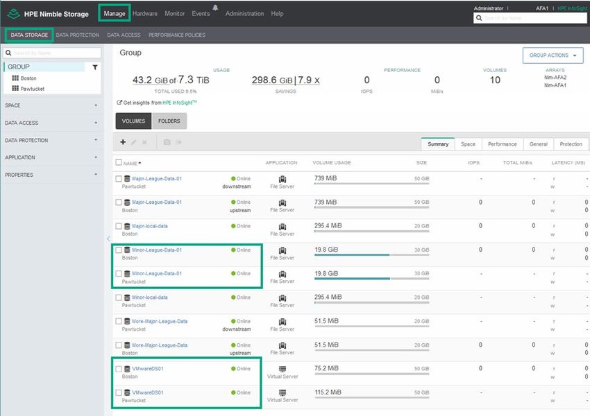
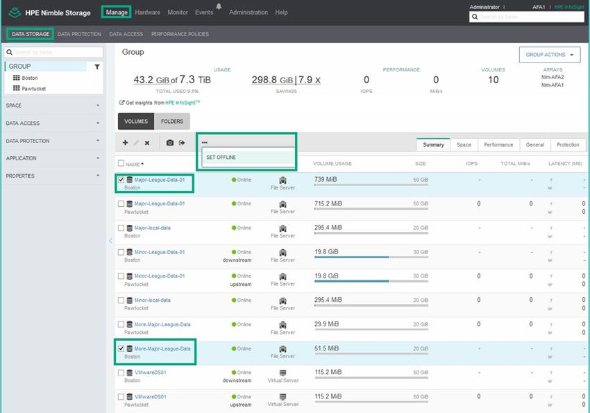
Technical white paper                                                                                                              Page 9

FIGURE 4. Volume Collections list showing synchronous replication with each array acting as the source for a volume collection

Note that the array operating system’s UI sometimes uses the term upstream for source volumes or pools and the term downstream for
destination volumes or storage pools, as the example in Figure 5 shows. This terminology is an artifact from previous generations of
NimbleOS, in particular with regard to asynchronous replication. With asynchronous replication, the array group that hosts the original
volume and manages the state of a replica has historically been called the upstream partner because the data flows from it. The array group
where the replica resides has been called the downstream partner because the data flows to it.

FIGURE 5. Bidirectional synchronous replication of two volumes shown in the array group’s volume list

NETWORK REQUIREMENTS AND CONSIDERATIONS
HPE Nimble Storage and HPE Alletra 6000 arrays are typically configured to connect to a management network and to data networks.
Although the array operating system permits the combining of management and data networks, such a configuration requires special care to
configure properly and is not ideal for Peer Persistence. Having separate management and data networks reduces traffic contention and
makes it less likely for synchronous replication traffic to exceed the maximum RTT value of 5 ms. For a solid, well-performing Peer
Persistence configuration, it is vital to build as much redundancy as possible into the network plumbing.
When HPE Nimble Storage and HPE Alletra 6000 arrays are deployed to use Peer Persistence, network resiliency is critical. Both the
management network and the data networks must span the two sites where the participating arrays are located (that is, the same IP address
subnet range must be available across the two sites).

IMPORTANT
Multiple traffic types (group, synchronous replication, management, and iSCSI data access) all require the same network subnet to be
available to all arrays in the group. These ports must be able to communicate on layer 2 of the TCP/IP model.

In addition to supplying access to the array group for administrative purposes, the management network serves as the conduit for
communication between the arrays and the Witness. The two arrays in the group use the management network to confirm their health with
the Witness and to coordinate group tasks, including replication. For that reason, it is important to connect the management network to a
redundant Ethernet network to ensure adequate performance (a maximum latency of 250 ms between the arrays and the Witness) and high
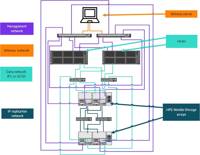
Technical white paper                                                                                                               Page 10

availability. Although the Witness does not need to be on the same subnet as the array group’s management network, the Witness IP
addresses must be routable from the array group’s management address, ideally through the default gateway.
Besides management traffic, the other network traffic type for HPE Nimble Storage and HPE Alletra 6000 arrays is data. The data traffic
type is used for host connectivity on iSCSI arrays, but it can also be used for array group traffic to move or copy data between the arrays
within a group. For Peer Persistence, a data network is used for synchronous replication of volumes between the two arrays in the group. For
asynchronous replication, a management network or a data network can be chosen for the replication network as part of the replication
partner configuration. Note that HPE Nimble Storage and HPE Alletra 6000 arrays do not send any replication data across FC interfaces; all
replication occurs on IP address networks.
HPE Nimble Storage arrays have options for 1 Gbps, 10 Gbps, and 25 Gbps Ethernet connectivity. HPE Alletra 6000 arrays have all of those
options along with a 100 Gbps option. Any of these Ethernet options can be used for replication traffic as long as the network can satisfy the
required RTT of 5 ms or less to keep the volumes synchronized. Hewlett Packard Enterprise recommends using a redundant 10 Gbps or
faster Ethernet network for the replication network. The maximum supported distance for the replication network is 100 km. Figure 6 shows
a high-level view of the recommended network topology.

IMPORTANT
To provide maximum protection, Hewlett Packard Enterprise highly recommends having redundant links for replication and client access
and a minimum of 2x10 Gbps or faster Ethernet networks per controller for replication traffic.

FIGURE 6. HPE Nimble Storage and HPE Alletra 6000 Peer Persistence high-level network topology

For more information about network best practices, see HPE Nimble Storage Deployment Considerations for Networking – Ethernet Best
Practices, available on the HPE InfoSight portal.
Technical white paper Page 11
SUMMARY OF PEER PERSISTENCE FAILURE HANDLING
HPE Nimble Storage and HPE Alletra 6000 Peer Persistence is engineered to help insure continued access to business-critical data in the
event of an array failure or the failure of other components in the environment. The following table summarizes how Peer Persistence reacts
to various failures and how data availability is affected. HPE prioritizes data integrity over data availability, so in some cases volumes will be
taken offline even if one of the arrays is still functioning properly.
TABLE 3. Peer persistence failure handling
Failure Replication stopped ASO Host impact
Witness down No No, but ASO becomes impossible No
Single-site network communications No No No
to Witness failure
Array-to-array single-link failure No No No
Array-to-array all-link failure Yes Yes All host I/O now happens at GL array
Site 1 to Witness and array-to-array Yes Yes Site 2 becomes primary
all-links failure
Site 2 to Witness and array-to-array Yes Yes Site 1 becomes primary
all-links failure
Array-to-array all-link failure and Yes No Yes—array group stops serving I/O on both sites
Witness links down from both sites
Witness and ASO not set up, then Yes No (Without Witness, there is no • Site with GL array remains online
complete loss of all array replication ASO or AFO.)
links • Site with BGL array has volumes inaccessible
until array secondary management IP is
accessed through SSH and array is converted to
GL
Witness and ASO not set up, GL array Yes No (Without Witness, there is no BGL site volumes go offline until array secondary
fails ASO or AFO.) management IP is accessed through SSH and array
is converted to GL.
Witness and ASO not set up, BGL Yes No (Without Witness, there is no GL array remains operational.
array fails ASO or AFO.)
General notes
• Peer Persistence is the only recommended mode of sync replication on HPE Nimble Storage and HPE Alletra 6000 arrays because it
enables seamless transitioning of GL ownership and automatic switchover of operations. Consider any other deployment at your own risk.
• Stretched networks across both sites are essential. Typically, the sites have three subnets with iSCSI arrays (management, group, and
data) and two subnets with FC arrays (management and group).
• A Witness is essential, and it must live in a network to which all management interfaces can route (although there is no need for it to be on
the same network).
• Installing the HPE Nimble Storage host toolkits is essential. You should consider any hosts without support for the toolkits as being unable
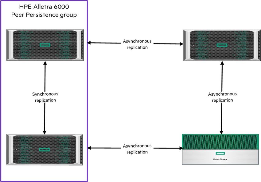
to participate in Peer Persistence.Technical white paper Page 12 PEER PERSISTENCE COMBINED WITH ASYNCHRONOUS SNAPSHOT REPLICATION For synchronous replication with Peer Persistence between two HPE Nimble Storage or HPE Alletra 6000 arrays, the arrays must be in the same array group and of the same array model. For asynchronous replication between two HPE Nimble Storage or HPE Alletra 6000 arrays, the arrays must be in different array groups. This means that you cannot perform both synchronous and asynchronous replication between the same two arrays. It is valid, however, to have two arrays in a group synchronously replicating some volumes between their two pools while also asynchronously replicating other volumes to asynchronous replication partners (either different array groups or HPE Cloud Volumes Block repositories). Any given volume on the arrays in the Peer Persistence group can be part of a volume collection that is being synchronously replicated between the two storage pools in the array group. Alternatively, a volume can be part of a volume collection that is being asynchronously replicated between the Peer Persistence array group and another HPE Nimble Storage or HPE Alletra 6000 array group. However, a volume cannot be replicated both synchronously and asynchronously. In fact, a volume might not be configured for replication at all; it depends on the data protection requirements for the information in the volume. For volumes with an RPO of zero or near zero, use Peer Persistence. For volumes with an RPO measured in minutes or more, use asynchronous snapshot replication. For volumes with no RPO, no replication is necessary. FIGURE 7. Peer Persistence and asynchronous snapshot replication example INSTALLATION AND SETUP PROCEDURES This section describes one way to set up a robust HPE Nimble Storage or HPE Alletra 6000 Peer Persistence environment. As with most challenges, there is no one-size-fits-all solution, but these steps offer some guidance to achieve positive results. Installing and configuring the Witness The Witness is currently distributed in two forms: • As an RPM installation package for users who want to manually install the service on a Linux® server • As an open virtual appliance (OVA) package for VMware users who want to deploy a packaged Linux VM with the Witness preinstalled A separate Witness deployment (on a different server) is required for each HPE Nimble Storage or HPE Alletra 6000 group of arrays that is configured for Peer Persistence. The Witness does not need to be on the same subnet as the array group, but its IP address must be routable from the array group’s management network. The Witness can be installed in a different data center or even in a cloud environment.
Technical white paper                                                                                                           Page 13

IMPORTANT
If ASO is used, the Witness client should be located in a third failure domain.

IMPORTANT
Do not deploy the Witness client on a server that depends on one of the arrays in the Peer Persistence group for its storage.

Deploy the Witness by using the RPM package
This procedure describes how to install and configure the Witness service by using the Linux yum command line utility.
1. Download the latest version of the Synchronous Replication Witness RPM package from the HPE InfoSight portal, in the Resources →
   Alletra 6000, Nimble Storage → Software Downloads section.

FIGURE 8. Synchronous Replication Witness download page
Technical white paper                                                                                                                    Page 14

2. If necessary, stand up a new Linux server to host the Witness service.
    CentOS 7.7.1908 is the current supported operating system for the Synchronous Replication Witness, but the latest details are listed on
    the HPE InfoSight portal page where the Witness software is posted.

FIGURE 9. CentOS 7 network installation menu

3. Configure static IPv4 addresses.
    A minimal installation of the OS is all that is required, but the server needs a static IP address that will be reliably accessible from the
    management network of the array group. IPv6 should be disabled (all communications with the array group use IPv4 addressing). See
    the CentOS release notes for other minimum system requirements for the server.

FIGURE 10. Static IP address, subnet, and DNS settings for CentOS server
Technical white paper Page 15
4. Upload the Witness RPM package to the Linux server and use the root account to log in to the server.
5. Run the chmod 775 command to make sure that the executable attribute is set on the
file.
6. Use the yum utility to install the RPM package: yum install –y .
NOTE
All dependent RPM packages are installed at this time, so internet access might be required.
FIGURE 11. Installation process for Witness service
7. After the Witness is installed, run the systemctl start nimble-witnessd.service command to start the service.
To automatically start the Witness service whenever the Linux server reboots, run the systemctl enable nimble-
witnessd.service command.
8. Run the systemctl status nimble-witnessd.service command to confirm that the Witness is running.
FIGURE 12. Output for command to check the status of the Witness service
9. If there are problems with installing or starting the Witness, examine the witnessd.log file in the /var/log/NimbleStorage
directory for troubleshooting clues.
10. Create a user account that allows the arrays to communicate with the Witness service.
A standard user account has sufficient privileges, so there is no need to create an account with root privileges. Use the following two
commands:
– useradd
– passwdTechnical white paper Page 16
FIGURE 13. User account for Witness activities created
11. At this point, as a good practice, use the same systemctl status nimble-witnessd.service command to restart the Witness
server; then log in as root and confirm that the Witness service is running.
12. Update the CentOS firewall to open the proper port for communication from the array group to the Witness.
FIGURE 14. Open port 5395 on the CentOS firewall and reload the firewall service
After the Witness service is deployed on a CentOS server (either a physical server or a VM), the next task is to configure the other components of the Peer
Persistence environment.
Deploy the Witness by using the OVA
IMPORTANT
This section is unnecessary if the Witness service has already been installed by using the RPM package. Do not install the Witness twice for
one Peer Persistence instance. If the OVA method is preferable, however, it must be deployed from VMware vCenter® by using the procedure
described in this section.
1. Download the latest version of the Synchronous Replication Witness OVA package from the HPE InfoSight portal, in the Resources →
Alletra 6000, Nimble Storage → Software Downloads section.
The VM that is included in the Witness OVA has the following hardware components:
– 1 CPU
– 4 GB of RAM
– 16 GB of hard disk capacity
– 1 SCSI controller (LSI Logic Parallel)
– 3 VMXNET virtual network adapters
2. Log into the VMware vSphere® Client to access the VMware vCenter instance where the OVA is to be deployed.Technical white paper Page 17 3. Right-click the desired VMware vSphere ESXi™ host and choose Deploy OVF Template from the menu. FIGURE 15. Initiate OVA deployment in vCenter 4. Select the Local file option and click Browse to choose an OVA file to download from the HPE InfoSight portal. FIGURE 16. Choosing the OVA file to deploy
Technical white paper                                                                                                              Page 18

5. Step through the open virtualization format (OVF) deployment wizard, specifying a name for the new VM and other details such as the
   compute resource where the VM will reside.

FIGURE 17. Supply a name and location for the new VM

6. Continue through the deployment wizard, specifying the data store to be used for storage, the virtual networks to be used for
   communications with the array group, and (if desired) external networks.
Technical white paper                                                                                                              Page 19

7. Specify a minimum of one static IP address, its netmask, and a gateway IP address to complete the initial deployment of the Witness VM.

NOTE
The netmasks required for this step are the IPv4 slash notation or Classless Inter-Domain Routing (CIDR) values, not the four octet notation
values. For example, 24 rather than 255.255.255.0 is the proper entry.

FIGURE 18. Required network information for initial setup of the Witness VM

8. In addition to the minimum network settings, Hewlett Packard Enterprise highly recommends that you configure the rest of the network
   connections, either as part of this setup or manually after the VM has been deployed.
    Redundant networks are very important to help the array group maintain contact with the Witness, and identifying a DNS server helps
    the CentOS server connect to other network resources through their host names instead of their IP addresses.
Technical white paper Page 20 9. Review all of the settings and click Finish to deploy the Witness VM. FIGURE 19. Final chance to review and change any setting. 10. After the Witness VM is fully deployed, power on the VM and open its web console to perform the initial login. FIGURE 20. Using the vSphere Client Actions menu to power on the Witness VM
Technical white paper                                                                                                                Page 21

11. As part of the login process, change the supplied default password to a new password.
    Hewlett Packard Enterprise supplies a default root password for the initial login, but this password must be changed immediately. The
    initial root password is listed in the Notes section of the software download page for the Witness OVA in the HPE InfoSight portal. The
    password is also provided in the HPE Nimble Storage and HPE Alletra 6000 Administration Guide documentation for NimbleOS versions
    5.2.1 and higher, also available on the HPE InfoSight portal.
    The new, user-defined password must be at least eight characters in length and conform to some additional requirements, such as not
    containing the word root or any words commonly found in a dictionary. Be aware that the initial login process times out in 60 seconds, so
    if you encounter delays while typing in the original and new passwords (twice each), it will be necessary to repeat the process until it is
    completed in the allowed timeframe.

FIGURE 21. Initial login session with Witness VM

12. Verify that the Witness service is running by running the command systemctl status nimble-witnessd.service from the
    CentOS command prompt.

FIGURE 22. Confirmation that the Witness service is running
Technical white paper Page 22
13. Create a user account that allows the arrays to communicate with the Witness service.
A standard user account has sufficient privileges, so there is no need to create an account with root privileges. Use the following two
commands:
– useradd
– passwd
FIGURE 23. Adding a new user-named Witness and setting the password
14. Run the command firewall-cmd –list-services to confirm that nimble-witness and ssh are the two services permitted
through the firewall.
As part of the security configuration for the Witness VM, IPv6 and other services are disabled on the CentOS server image.
FIGURE 24. Query the firewall for a list of the services that are permitted to pass through
After the Witness service is deployed on a CentOS server VM, the next task is to configure the other components of the Peer Persistence
environment.
NOTE
Hewlett Packard Enterprise will update the OVA package as necessary to incorporate new OS patches or features. Users should not use
other sources to update components of the Witness server unless directed to do so by HPE Nimble Storage Support.
Configuring the host
The appropriate NCM package is required for installation on all hosts. NCM is currently available for Windows, VMware, and Linux operating
systems. Check the HPE InfoSight Validated Configuration Matrix for the NCM version for your NimbleOS release, as well as for associated
release notes.
Setting up the Initial array configuration
The basic steps for setting up HPE Nimble Storage and HPE Alletra 6000 arrays are the same whether the arrays are being configured for
Peer Persistence or not. The array hardware guide and administration guides, available on the HPE InfoSight portal, explain the steps in
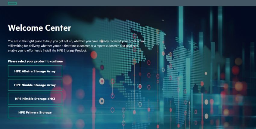
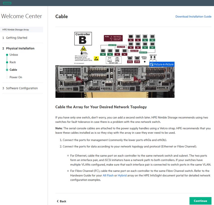
detail. In addition, the HPE InfoSight Welcome Center, shown in Figure 25, is a useful online tool.Technical white paper Page 23 FIGURE 25. The HPE InfoSight Welcome Center landing page The Welcome Center provides a range of information, from summaries of the requirements and steps to videos and text-based best practices for installing and configuring the arrays. Figure 26 shows an example page. FIGURE 26. Example content from the HPE InfoSight Welcome Center
Technical white paper                                                                                                                   Page 24

As part of the initial setup, two or three IP address subnets should be created on the first array. For iSCSI arrays, ideally, separate subnets are
dedicated to management, group, and data traffic. For FC arrays, only the management and group IP address subnets are required because
all host data traffic goes across the FC interfaces. If desired, the group traffic can be run on the same subnet as the management or the iSCSI
data traffic, but it is important to maintain the latency of 5 ms or less for the group traffic.
On arrays with only the FC protocol enabled (not both FC and iSCSI), there is no group traffic type to select—only management and data.
Any add-on IP interfaces in the controllers for FC arrays are assumed to be intended for group traffic.
Note that group traffic refers to the data replication activity between the two arrays in the group. There is also some group-related traffic
that goes across the management subnet between the two arrays.

IMPORTANT
Latency should remain at less than 5 ms round-trip response time between arrays in the group on all synchronous replication links.

Figure 27 shows an example configuration of subnet information for an array group.

FIGURE 27. Configured subnet information for array group

After the subnets are defined, it is necessary to bind them to specific ports on the array controller. Remember that high availability is very
important for Peer Persistence, and make sure that each subnet is assigned to at least two ports per controller. This arrangement enables
routing through redundant switches for a more robust configuration.

FIGURE 28. Associating subnets and Ethernet ports
Technical white paper                                                                                                                    Page 25

Before adding the second array to the group, be sure to define a secondary management IP address in the network configuration. After
the group is built and synchronous replication is enabled, this secondary management IP address can be used to open an SSH session to the
BGL if the GL becomes unresponsive. Figure 29 shows an example of configuring the secondary management IP address.

NOTE
You cannot access the secondary IP address through the array group’s GUI. The secondary management IP address is used only for
interaction with the BGL, it and it can be reached only through the CLI in an SSH session.

FIGURE 29. Configuring the secondary management IP address

Adding the second array
The first array is ready to scale out with the addition of the uninitialized second array. The second array is easily added in the first array’s GUI
by selecting the Hardware tab at the top of the screen and choosing Add Array to Group in the Actions
drop-down menu, as shown in Figure 30.

FIGURE 30. Initiating addition of the second array to the group
Technical white paper                                                                                                               Page 26

All of the powered-on HPE Nimble Storage and HPE Alletra 6000 arrays on the local network are listed, but only arrays that are running the
same version of the array operating system are selectable from the list. Figure 31 shows an example list. In general, it is possible to group
HPE Alletra 6000 arrays with HPE Nimble Storage arrays, but for Peer Persistence the two arrays must be of the same model.

FIGURE 31. List of discovered HPE Nimble Storage arrays

The interface ports on the second array should be assigned to the subnets that were created during the setup of the first array. To enable
ASO, the subnets must span the two sites where the arrays are located. Figure 32 shows the hardware view of the resulting group.

FIGURE 32. Hardware view of the group
You can also read