Gold Dust Solar, LLC Project - N-100357 Bureau of Land Management U.S. Department of the Interior Prepared for - Bureau of Land ...
←
→
Page content transcription
If your browser does not render page correctly, please read the page content below
PLAN OF DEVELOPMENT

Gold Dust Solar, LLC Project
                   N-100357

                           Prepared for
     U.S. Department of the Interior
Bureau of Land Management
              Tonopah Field Office

                           Submitted by

                   Gold Dust Solar, LLC
                       c/o Arevia Power

                              July 28, 2021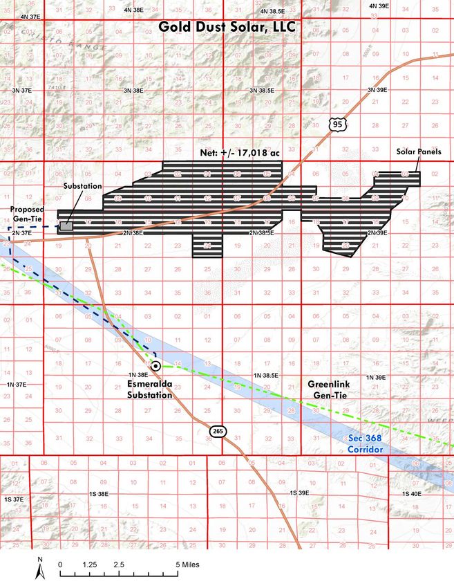
CONTENTS
Contents.......................................................................................................................................... i
Section 1 ..................................................................................................................................... 1-4
Project Description .................................................................................................................... 1-4
   1.1 Introduction ............................................................................................................... 1-4
         1.1.1 Type of Facility, Planned Uses, Generation Output ................................ 1-4
         1.1.2 Applicant’s Schedule for the Project.......................................................... 1-4
   1.2 Proponent’s Purpose and Need for the Project ..................................................... 1-5
         1.2.1 Need for Renewable Energy ....................................................................... 1-5
         1.2.2 Project Purpose and Need ........................................................................... 1-6
         1.2.3 Power Market and Project Benefits............................................................ 1-7
   1.3 General Facility Description, Design, and Operation .......................................... 1-8
         1.3.1 Project Location, Land Ownership, and Jurisdiction .............................. 1-8
         1.3.2 Legal Land Description ............................................................................... 1-8
         1.3.3 Total Acreage and General Dimensions of All Facilities and
                      Components ................................................................................................ 1-10
         1.3.4 Project Elements ......................................................................................... 1-10
         1.3.5 Project Facilities .......................................................................................... 1-11
         1.3.6 Linear Facilities ........................................................................................... 1-17
         1.3.7 Interconnection Facilities .......................................................................... 1-18
         1.3.8 Water and Wastewater .............................................................................. 1-18
         1.3.9 Lighting ....................................................................................................... 1-18
         1.3.10 Waste and Hazardous Materials Management...................................... 1-19
         1.3.11 Fire Protection............................................................................................. 1-20
         1.3.12 Health and Safety Program....................................................................... 1-20
         1.3.13 Stormwater Management.......................................................................... 1-21
         1.3.14 Vegetation Management ........................................................................... 1-21
   1.4 Alternatives .............................................................................................................. 1-21
   1.5 Other Permits and Authorizations ....................................................................... 1-22
   1.6 Financial and Technical Capability of the Applicant ......................................... 1-23
Section 2 ..................................................................................................................................... 2-1
Construction of the Facilities ................................................................................................... 2-1
   2.1 Overview .................................................................................................................... 2-1
   2.2 Temporary Construction Workspace, Laydown and Mobilization Areas ........ 2-1
   2.3 Site Preparation ......................................................................................................... 2-1
         2.3.1 Land Surveying and Staking ...................................................................... 2-1
         2.3.2 Vegetation Removal and Treatment .......................................................... 2-2
         2.3.3 Site Clearing, Grading, and Excavation .................................................... 2-2
         2.3.4 Gravel, Aggregate, and Concrete Needs and Sources ............................ 2-2
   2.4 PV Solar Array Assembly and Construction ......................................................... 2-3
   2.5 Electrical Collection and Transmission System Construction ............................ 2-3
         2.5.1 Standard Transmission Line Construction Techniques .......................... 2-4

Gold Dust Solar, LLC – N-100357                                          i                                                       July 28, 2021
Plan of Development
2.6 Road System Construction....................................................................................... 2-5
2.7 Substation Construction ........................................................................................... 2-5
2.8 Site Stabilization, Protection, and Reclamation .................................................... 2-6
2.9 Workforce, Schedule, Equipment, and Materials ................................................. 2-6
2.10 Construction Traffic ................................................................................................ 2-10
2.11 Construction Power ................................................................................................ 2-10
Section 3 ..................................................................................................................................... 3-1
Related Facilities and Systems ................................................................................................. 3-1
3.1 Transmission System Interconnect ......................................................................... 3-1
3.1.1 Proposed Transmission System ................................................................. 3-1
3.1.2 Ancillary Facilities........................................................................................ 3-1
3.1.3 Status of Power Purchase Agreements ..................................................... 3-1
3.1.4 Status of Interconnection Agreement ........................................................ 3-1
3.1.5 General Design and Construction Standards ........................................... 3-1
3.2 Gas Supply Systems .................................................................................................. 3-2
3.3 Other Related Systems.............................................................................................. 3-2
3.3.1 Communication System Requirements ..................................................... 3-2
Section 4 ..................................................................................................................................... 4-1
Operation and Maintenance .................................................................................................... 4-1
4.1 Operation and Maintenance .................................................................................... 4-1
Section 5 ..................................................................................................................................... 5-1
Environmental Considerations ................................................................................................ 5-1
5.1 Site Characteristics and Potential Environmental Issues .................................... 5-1
5.2 Other Uses on the Project Site ................................................................................. 5-1
5.2.1 Military Aviation .......................................................................................... 5-2
5.3 Design Features ......................................................................................................... 5-2
5.4 Mitigation Measures ................................................................................................. 5-3
Section 6 ..................................................................................................................................... 6-1
References ................................................................................................................................... 6-1
Figures
Figure 1-1 Project Location Map ...................................................................................... 1-9
Figure 1-2 Typical Array Configurations...................................................................... 1-13
Figure 1-3 Typical Mounting System ............................................................................ 1-14
Tables
Table 1-1 Applicant’s Project Schedule ......................................................................... 1-5
Table 1-2 Township/Range and Section Information ................................................. 1-8
Table 1-3 Summary of Permanent and Temporary Disturbance ............................. 1-10
Table 1-4 Wastes Potentially Generated by the Project ............................................. 1-19
Table 1-5 Hazardous Materials That May Be Used During Operation................... 1-21
Table 1-6 Federal, State, and Local Permits and Authorizations ............................. 1-24
Table 2-1a Estimated On-site Equipment for Solar Panel Array and Collection
System Construction ................................................................................................................. 2-7
Table 2-1B Estimated On-site Equipment for substation Construction ...................... 2-9
Table 2-1C Estimated On-site Equipment for Gen-Tie Line Construction.................. 2-9
Gold Dust Solar, LLC – N-100357 ii July 28, 2021
Plan of DevelopmentTable 4-1 Routine Maintenance Protocol ...................................................................... 4-3 Attachment A Preliminary Site Plan Gold Dust Solar, LLC – N-100357 iii July 28, 2021 Plan of Development
SECTION 1
Project Description

1.1 Introduction
1.1.1       Type of Facility, Planned Uses, Generation Output
Gold Dust Solar, LLC (Applicant) proposes to construct, own, operate, and decommission the
Gold Dust Solar LLC Solar Project (Project), consisting of up to a nominal 1.5-gigawatt (GW)
alternating current (GWac) solar photovoltaic (PV) power generating facility and 1-gigawatt
Battery Energy Storage System (BESS) on Bureau of Land Management (BLM)-administered
land located in Esmeralda County, Nevada. The Project would be constructed using photovoltaic
solar modules mounted on single-axis, horizontal tracker structures combined with an integrated
Battery Energy Storage Systems.

The Project will be located on approximately 17,018 acres of BLM administered land. The ROW
application contains a larger area than required for the solar field to allow for adjustments in the
facility layout to minimize environmental impacts, based on the National Environmental Policy
Act (NEPA) analysis.

The power produced by the Project would be conveyed to the NV Energy (“NVE”) transmission
system. The project sponsor will submit an Interconnection Application to NVE for 1.5 GW at
the planned 525kV/345 kV Esmeralda Substation, part of the Greenlink West transmission line.

Average annual energy production from a 1.5 GWac Project equates to the annual daytime
electricity needs of approximately 860,000 households. Solar electric power is produced during
daylight hours when electricity demand is highest which will be coupled battery energy storage
technology in order to improve the customer’s energy product. The Project would generate
greenhouse gas-free electricity that would offset approximately 3.2 million metric tons of carbon
dioxide and other emissions that would result from producing an equivalent amount of electricity
from fossil fuel-fired electric generators.

1.1.2       Applicant’s Schedule for the Project
The BLM would be the lead federal agency for approving the Project and would issue a ROW
grant authorizing the use of BLM-administered lands for Project construction, operation, and
decommissioning. The project site is within a “variance area” for solar power plant development,
as defined in the Record of Decision prepared for the Final Programmatic Environmental Impact
Statement (EIS) for Solar Energy Development in Six Southwestern States (Solar PEIS). Utility-

Gold Dust Solar, LLC – N-100357                 1-4                                     July 28, 2021
Plan of Development
scale solar energy development projects in variance areas is permitted subject to site-specific
conditions. All such projects are required to comply with the National Environmental Policy Act
(NEPA) and other applicable laws. Preparation of an EIS is expected to be required; the
completion of the EIS process and issuance of a ROD is targeted for the Third Quarter 2023.
Further detail on the project schedule is provided in Table 1-1.

Prior to any activity on the site, required resource management plans would be developed and
approved, and regulatory and permit conditions would be integrated into the final construction
compliance documents. Project construction would begin once all applicable approvals and
permits have been obtained. Construction is expected to take approximately 24 months and would
include the major phases of mobilization, construction grading and site preparation, installation of
drainage and erosion controls, PV panel/tracker assembly, and solar field construction. The
Applicant is planning to commence construction in the fourth quarter of 2024. Once construction
is completed, the Project would be in operation for at least 30 years with the possibility of a
subsequent repowering for additional years of operation.

                             TABLE 1-1        APPLICANT’S PROJECT SCHEDULE
 Activity                                               Date
 NEPA Notice of Intent                                  4th Quarter 2021
 BLM Permitting/NEPA (EIS) Process Complete             3rd Quarter 2023
 Construction Commencement                              4th Quarter 2024
 Startup and test                                       4th Quarter 2026
 Commercial operation                                   December 31, 2026

1.2 Proponent’s Purpose and Need for the Project
1.2.1         Need for Renewable Energy
The United States has a greater solar energy resource potential than any other industrialized
nation. The multiple benefits associated with developing this resource have been recognized
repeatedly by both federal and state policy-makers. Development of solar resources reduces
reliance on foreign sources of fuel, promotes national security, diversifies energy portfolios and
contributes to the reduction of greenhouse gas emissions. The demand for power continues to
grow in the Western United States. As older technology fossil-fuel plants reach the end of their
useful lives, there is a need to replace them with clean, reliable resources. Recognizing this need,
many Western states, including Nevada, have enacted legislation to encourage or mandate the
development of renewable generation.

Nevada’s Renewable Portfolio Standard (RPS requires 50% of all electricity generated in Nevada
be derived from renewable sources by 2030. State government agencies were directed to take all
appropriate actions to implement this target in all regulatory proceedings, including siting,
permitting, and procurement for renewable energy power plants and transmission lines. The RPS

Gold Dust Solar, LLC – N-100357                  1-5                                    July 28, 2021
Plan of Development
in Nevada and other states has created a competitive market for contracts to sell renewable
energy, with success determined on the basis of “least cost, best fit” criteria.
Nevada has passed legislation requiring utilities to phase out their use of coal-fired generation and
partially replace that generation with renewable energy, as well as legislation that amended the
existing RPS laws, resulting in requirements for utilities to increase their use of renewable energy
(SB 123, SB 252). In order to achieve these goals, it is necessary to build new renewable energy
facilities, including substantial solar energy facilities such as the proposed Project. The Applicant
believes that the Project would generate electricity that is cost-competitive with electricity from
other types of renewable projects.
The federal government has enacted legislation strongly encouraging the development of
renewable energy. As part of an overall strategy to develop a diverse portfolio of domestic energy
supplies for our future, the National Energy Policy of 2001 and the Energy Policy Act of 2005
(Public Law 109-58, August 8, 2005) encourage the development of renewable energy resources,
which includes solar energy. Section 211 of the Energy Policy Act of 2005 encourages the
approval of at least 10,000 MW of non-hydropower renewable energy production on the public
lands; this goal was met in 2012. In early 2009, the Secretary of the Interior issued Orders 3283
and 3285, making the production, development, and delivery of renewable energy top priorities
for the Department of the Interior. The President’s Climate Action Plan, released on June 25, 2013,
sets forth a new goal for the Department of the Interior to approve 20,000 MW of renewable energy
projects on the public lands by 2020. Congress is also considering legislation that would
implement greenhouse gas emissions requirements and/or national renewable portfolio standards.
Part of the government’s efforts to promote renewable energy depend on the ultimate
development of increasingly economical facilities that drive down the price of renewable energy,
and ultimately enable it to compete in the market place with fossil fuel facilities.
1.2.2 Project Purpose and Need
The fundamental purpose of the Project is to construct a clean, renewable source of solar
electricity that helps meet the region’s growing demand for power and helps fulfill national and
state renewable energy and greenhouse gas emission goals. Solar energy provides a sustainable,
renewable source of power that helps reduce fossil fuel dependence and greenhouse gas
emissions. Considering the entire process, from raw material sourcing through end-of-life-cycle
collection and recycling, 1.5 GWac of additional generating capacity would produce a small
fraction of the greenhouse gas emissions of a similar capacity fossil fuel plant.
Specific Project objectives are:
• Establish a solar PV power-generating facility that is of sufficient size and configuration
to produce approximately 1.5GWac of electricity in order to provide Northern Nevada a
significant new source of renewable energy.
• Produce and transmit electricity at a competitive cost.
Gold Dust Solar, LLC – N-100357 1-6 July 28, 2021
Plan of Development• Initiate construction of the Project during calendar year 2024 in order to qualify for the
federal solar Investment Tax Credit (ITC).
• Locate the facility in rural Esmeralda County in proximity to an available connection to
the upgraded NVE electrical distribution infrastructure.
• Minimize environmental effects by:
o Avoiding Exclusion Areas identified in the Solar PEIS ROD;
o Using existing electrical distribution facilities, rights-of-way, roads and other existing
infrastructure where practicable;
o Minimizing water use during operation;
o Reducing greenhouse gas emissions.
• Using solar technology that is available, proven, efficient, and easily maintained,
recyclable, and environmentally sound.
1.2.3 Power Market and Project Benefits
The Project would interconnect to the planned Esmeralda Substation, part of the Greenlink West
project. The interconnection would allow NVE and 704b customers to purchase renewable energy
generated by the Project under one or more Power Purchase Agreements (PPAs) to deliver energy
from a (nominal) 1.5 GWac generating facility.
The Project is well suited to arid environments because of the technology’s low water consumption.
This is a key consideration in Nevada and the Western U.S., as the population grows and water
supplies become more constrained. PV solar technology, which converts sunlight directly into
electrical energy, entails no thermal process, and therefore does not require process or cooling water
to produce electricity. Water consumption during operations would consist of dust control and
domestic use for on-site personnel and is between 95 and 99 percent less than concentrating solar
projects that employ conventional steam turbines to generate electricity.
The Project would also create employment for Nevada residents. The Project is anticipated to
create an average of 1,000 construction jobs at any given time, and create up to 20+ long-term
full-time-equivalent (FTE) operational jobs. These jobs would in turn support many other jobs in
the Nevada economy.
Gold Dust Solar, LLC – N-100357 1-7 July 28, 2021
Plan of Development1.3 General Facility Description, Design, and
Operation
1.3.1 Project Location, Land Ownership, and
Jurisdiction
The Project site is located in Esmeralda County, Nevada, approximately 22 miles west of the
town of Tonopah. U.S. Route 6/95 bisects the site and State Route 265 is located to the
southwest.
The Project is located entirely on federal lands administered by the BLM under the 1997 Tonopah
Resource Management Plan. The Project site is located within a variance area for solar power
generation under the 2012 Approved Resource Management Plan Amendments/Record of
Decision for Solar Energy Development in Six Southwestern States.
1.3.2 Legal Land Description
The Project is located on the property identified in the table below, all located within the Mount
Diablo Base and Meridian. Specific township/range and section information is shown in Table 1-
2.
TABLE 1-2 TOWNSHIP/RANGE AND SECTION INFORMATION
Township Range Sections Description
2N 38E 1 and 2 All
3 SE1/4SE1/4, S1/2
9 E1/2, E1/2NW1/4, SW1/4NW1/4, SW1/4
10 thru 17 All
18 E1/2
24 All
2N 38 ½E 5 thru 9 All
17 N1/2, SW1/4, N1/2SE1/4, SW1/4SE1/4
18 All
2N 39E 3 S1/2
4 SE1/4
7 NW1/4, S1/2
8 S1/2
9 E1/2, E1/2NW1/4, SW1/4NW1/4
10 NW1/4, N1/2SW1/4, SW1/4SW1/4
16 N1/2, SW1/4, N1/2SE1/4, SW1/4SE1/4
17 All
18 N1/2, SE1/4
19 E1/2NE1/4, E1/2SE1/4
20 All
21 W1/2NW1/4
Gold Dust Solar, LLC – N-100357 1-8 July 28, 2021
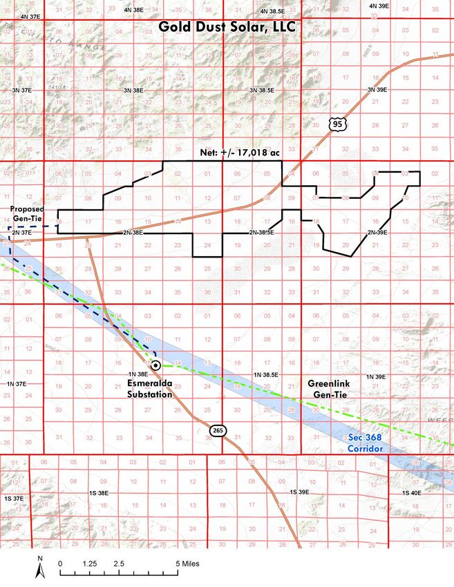
Plan of DevelopmentFIGURE 1-1 PROJECT LOCATION AND GEN-TIE MAP
Solar Field
Solar Field
Gold Dust Solar, LLC – N-100357 1-9 July 28, 2021
Plan of Development1.3.3 Total Acreage and General Dimensions of All
Facilities and Components
Table 1-3 lists Project facilities and the associated permanent and temporary disturbance
acreages. The proposed site plan is provided in Attachment 1.
TABLE 1-3 SUMMARY OF PERMANENT AND TEMPORARY DISTURBANCE
Acres of
Disturbance Type Disturbance Notes
Permanent Disturbance
Solar facility 17,018 1.5 GWac PV solar facility and 1 GWac BESS.
Collection line road to Esmeralda 6 Up to 20 feet wide and 6 miles in length. Pole sites included.
Substation – 345kV Alignment
Access Road 15 Up to 20 feet wide and 5-6 miles in length
Total 17,039
Temporary Disturbance
Laydown area 10.0 Outside the solar facility fence
Collection line construction 11.5 10 pulling sites 100 feet by 500 feet
Total
21.5
1.3.4 Project Elements
The Project would include the following primary elements (see Attachment 1):
• Solar array blocks consisting of solar photovoltaic modules mounted on single-axis,
horizontal tracker mounting systems supported by driven steel posts or other embedded
foundation design;
• Direct current (DC) collection system and Power Conversion Stations (PCSs) to collect
power from the array blocks;
• Overhead 34.5 kV AC collection system to convey electricity from the PCSs to the
substation;
• Energy storage system;
• An internal roadway system consisting of spoke, ring, and perimeter roadways;
• Access roads along project generation tie-lines;
• One to three additional on-site switchyards hosting on-site ringbus switchyard(s);
Gold Dust Solar, LLC – N-100357 1-10 July 28, 2021
Plan of Development• Generation tie-line extending from the project switchyard(s) to the planned Esmeralda
Substation, consisting of one 525kv or 345 kV circuit (right-of-way width to be
determined);
• Administrative and maintenance buildings;
• Redundant telecommunication systems and cables installed in tandem with the gen-tie
routes. Microwave and wireless systems also onsite;
• Meteorological towers (steel lattice), approximately 30 feet high, mounted on concrete
foundations may be installed around the perimeter of the solar field;
• Project security using a combination of perimeter security fencing, controlled access
gates, onsite security patrols, lighting, electronic security systems and/or remote
monitoring;
• A 10-foot wide firebreak outside the perimeter fence;
• Drainage control structures, final design to be determined upon completion of a
hydrologic study;
• A temporary construction mobilization and laydown area, which would contain
construction trailers, construction workforce parking, above ground water tanks,
materials receiving, and materials storage (graded/compacted earth).
1.3.5 Project Facilities
The Project would be designed in accordance with federal, state, and industrial standards,
including American Society of Mechanical Engineers standards, National Electrical Safety Code,
International Energy Conservation Code, International Building Code, Uniform Plumbing Code,
Uniform Mechanical Code, National Fire Protection Association, and Occupational Safety and
Health Administration regulations.
1.3.5.1 Solar Panel Arrays
The proposed Project would utilize high-efficiency commercially available solar PV modules that
are Underwriters Laboratory (UL)-listed or approved by another nationally recognized testing
laboratory. Materials commonly used for solar PV modules include monocrystalline silicon,
polycrystalline silicon, amorphous silicon, cadmium telluride (CdTe), and copper indium
selenide/sulfide.
The project would use monocrystalline or polycrystalline silicon solar PV modules mounted on
single-axis, horizontal tracker mounting systems. Mounted PV modules, inverters, and
transformers would be combined to form array blocks, approximately 2 MW in size.
With a horizontal tracker mounting system, the panel arrays are arranged in north-south oriented
rows and drive motors would rotate the horizontally mounted solar panels from east to west to
follow the sun (on a single axis) throughout the day. A typical panel array layout using horizontal
trackers is shown in Figure 1-2. The highest point for a horizontal tracker would be achieved
Gold Dust Solar, LLC – N-100357 1-11 July 28, 2021
Plan of Developmentduring the morning and evening hours when the trackers are tilted at their maximum angle, and would be a maximum of 12 feet above the ground surface depending on the grade where the posts are installed (Figure 1-3). When solar modules are roughly parallel to the ground, the overall height of the tracker unit would be a maximum of 6 feet above the ground surface depending on the grade where the posts are installed. Gold Dust Solar, LLC – N-100357 1-12 July 28, 2021 Plan of Development
FIGURE 1-2      TYPICAL ARRAY CONFIGURATIONS

Gold Dust Solar, LLC – N-100357                1-13   July 28, 2021
Plan of Development
FIGURE 1-3      TYPICAL MOUNTING SYSTEM

Gold Dust Solar, LLC – N-100357           1-14   July 28, 2021
Plan of Development
The vertical support legs for the tracker mounting system consists of foundations that may
include concrete piers approximately 18 to 24 inches in diameter and 6 to 8 feet deep, or driven
posts (wide flange I-beam) approximately 6 to 8 inches across and 6 to 12 feet deep. The
preferred mounting configuration would use directly embedded driven posts; concrete piers
would be used only if subsurface conditions do not support driven posts.
In this type of system, each tracker panel array is approximately 285 feet long and powered by a
low-voltage solar-powered drive motor. The motors and actuator are mounted to one of the driven
posts and do not require separate foundations for mounting. Hydraulic drive systems would not
be used. The motors only would be operated for a few seconds every 5 to 10 minutes during
daylight conditions to move the panels in approximately 1 degree increments. The sound from the
tracker motors would be less than 70 decibels at a distance of 3 feet. This would equate to less
than 30 decibels at 50 feet.
Meteorological stations located at the site would monitor wind speed and communicate with the
tracker units. This would allow for the trackers to rotate to a flat position during high wind
activity. The meteorological station towers would be located at multiple locations around the
perimeter of the solar array. Meteorological station towers would be monopole or lattice design
and would not exceed 30 feet in height. Each tower would require a small concrete foundation
approximately 3 feet by 3 feet that would extend approximately 4 feet into the ground, depending
on soil conditions.

Emergency Backup Power
If horizontal trackers are used, the PCSs would be equipped with emergency backup power
required to rotate the tracker units to their stow position in the unlikely event of high winds and a
loss of the primary electrical connection from the Project to the transmission system. The
emergency back-up power system would consist of a15 kilovolt-ampere (kVA) battery-based
uninterruptible power supply (UPS) at each PCS.

1.3.5.2     Electrical Collection System
PV modules convert sunlight into DC electricity. One or more combiner boxes would be located
in the array block to collect the DC electricity from PV modules. The electricity would be
delivered through underground cables to an inverter that changes the DC electricity to AC
electricity and a medium-voltage transformer that steps up the voltage to 34.5 kV. This converted
electricity then would be delivered to an onsite substation, where the electricity again would be
stepped up to 345 kV for delivery to the transmission grid.

Inverters, Transformers, and Medium Voltage Switchgear
Each array block would have a Power Conversion Station (PCS) containing inverters and medium
voltage transformers, as well as other electrical equipment. Each PCS also would contain
communication equipment to wirelessly communicate with the tracker units to control operation
and detect anomalous conditions. Photovoltaic Combining Switchgear, or PVCS, will be located
along the 34.5 kV collector line. All electrical equipment would be housed in protective
enclosures on concrete pads.

Gold Dust Solar, LLC – N-100357                 1-15                                     July 28, 2021
Plan of Development
34.5 kV Collection System
The 34.5 kV collection system would comprise both underground and overhead cabling. From the
medium-voltage transformers to the PVCSs, the 34.5 kV system would be installed underground
using 35 kV-rated medium voltage cables listed for direct buried applications except that
overhead cabling would be installed where necessary to avoid existing underground facilities.
Underground 34.5 kV cables would be installed to comply with the minimum burial depth in
accordance with the National Electrical Code.

From the PVCSs to the onsite substation, the 34.5 kV system would be installed overhead.
Overhead 34.5 kV collector lines would be installed as double circuit lines on wood poles with
post insulators (typical of medium voltage installations in electric distribution systems). Pole
height would be up to 75 feet above grade.

Substations
A 2.5-acre 345 kV Substation would be developed within the project site. Individual 35 kV
“Circuits” will feed approximately 10 blocks each. Substation would be constructed based on
applicable electrical safety codes. The substation would be separately fenced to provide increased
security around the medium and high voltage electrical equipment. The substation area would
include a transformer containment area, a microwave tower, a control house, and one or more
transformers. Containment measures for all substation equipment shall be provided in accordance
with Environmental Protection Agency 40 CFR Part 112 and all applicable codes required by the
local, state, and federal governing authorities. The transformer containment area would be lined
with an impermeable membrane covered with gravel, and would include a drain with a normally
closed drain valve. Transformers will be provided with secondary oil containment equal to 110%
of the volume of oil present in the transformer in addition to the volume of rain water for a 25-
year, 24-hour rainfall event.

1.3.5.3     Energy Storage
A battery energy storage system (BESS) would be located within the site. Approximately 1 GW
of battery systems will be installed at the project, with each battery system installed at an inverter.

1.3.5.4     Site Security and Fencing
Security at the Project site would be achieved by fencing, lighting, security patrols, and electronic
security systems. The Project site would be monitored 24 hours per day, seven days per week
during all phases. Lighting would be provided at the O&M building and Project entrance gate.
The solar field and support facilities perimeter would be secured with chain link metal-fabric
security fencing. Controlled access gates would be located at the site entrance. The perimeter
fence would be an approximately 6- to 7-foot-high chain link fence with 1-foot-high barbed-wire
security strands at the top; a 10-foot-wide fire break would be maintained around the exterior of
the perimeter fence (the security fence in proximity to the gen-tie line would be properly
grounded).

Gold Dust Solar, LLC – N-100357                  1-16                                     July 28, 2021
Plan of Development
1.3.5.5     Internal Project-Related Roads
Project-related roads within the solar plant site would include the perimeter road and solar field
access ways as described below. Similar to the disturbance that would occur from other Project
components (based on the assumption that all acreage within the fenced perimeter would be
disturbed), the acreage identified for roads also is considered to be permanent disturbance.

Perimeter Road
A new perimeter road would be located just inside the site’s perimeter fence and within the solar
field area around specific blocks of equipment. The perimeter road would be constructed to allow
access by maintenance and security personnel. The perimeter road would be approximately
20 feet wide and would be composed of native graded and compacted dirt. Alternatively, the
perimeter road may use an aggregate base in some or all areas to meet Project dust and flood
control requirements.

Solar Field Access Ways
Within the solar field, new access ways would be built to provide vehicle access to the solar
equipment (PV modules, inverters, transformers) for O&M activities. These access ways would
be approximately 20 feet wide and approximately every 500 to 1,300 feet across the solar field.
The existing surface area would be graded and compacted using onsite materials to facilitate use
by two-wheel-drive vehicles.

1.3.6       Linear Facilities
1.3.6.1     525kV or 345kV Gen-Tie Transmission Line
The Project would require the construction of an approximately 6 mile 525kV or 345kV circuit
and telecommunications system (fiber optic system data) for interconnection to the utility
transmission grid system at the planned Esmeralda Substation. The exact routing is still to be
determined. A 20-foot-wide gen-tie road would run the length of the gen-tie line. The overhead
line and telecommunications system (fiber optic system data) would be installed per local and
national electrical code requirements. Structures would be galvanized steel with a dull gray
appearance similar to existing steel poles installed adjacent to the site and would be used to
support interconnection to the transmission system.

All overhead electrical lines would be designed and installed in accordance with the Avian Power
Line Interaction Committee’s (APLIC) Suggested Practices for Avian Protection on Power Lines
(APLIC 2006). The Applicant also would prepare a Bird and Bat Conservation Strategy to
address potential impacts to birds and bats during the construction, operations, and maintenance
phases of the Project.

1.3.6.2     Access Roads
The primary access road for the Project during both construction and operation would be
determined during the design and EIS process to minimize overall impacts. Primary access routes
will be via U.S. Route 6/95 and State Route 265.

Gold Dust Solar, LLC – N-100357                 1-17                                    July 28, 2021
Plan of Development
1.3.7       Interconnection Facilities
Improvements to interconnection facilities are to be determined following detailed utility review
of the project.

1.3.8       Water and Wastewater
All Project-related water use and facilities are described below.

1.3.8.1     Water
An estimated 2,000 acre-feet (AF) of water would be required over the Project construction
period for construction-related activities, including dust control. After construction is complete,
the Project’s water consumption during operation would require up to 60 acre-feet per year.
Water would not be used for panel washing but would be used in conjunction with dust palliatives
during operation see Section 4.1, Operation and Maintenance. The Project would not require
process water. Water is anticipated to be purchased from a commercial source or a user with an
existing appropriation. It would then be trucked to the Project site where it would be stored in an
on-site water storage tank.

The BLM has allowed the use of several dust palliatives on other projects. If dust palliatives are
used in place of water for the Project, the total amount of water needed during construction would
be reduced. The Applicant may opt to use such palliatives, as authorized by the BLM for the
Project. The soil binder/dust palliatives that are proposed for the Project, and which BLM
previously has allowed are:
    •   Road Bond 1000
    •   For roads and heavy traffic areas: Soil Cement
    •   For non-traffic areas on finer soils: Formulated Soil Binder FSB 1000
    •   For non-traffic areas on sandier/rockier soils: Plas-Tex
    •   Alternatives as approved by BLM

1.3.8.2     Wastewater
Wastewater generated during construction would include sanitary waste from portable toilets.
This waste would be collected by a contracted sanitary disposal service and transported to a
licensed disposal facility. Since the facility will be manned by a small number of full time
employees, no permanent wastewater facilities would be installed and the same portable toilets in
use during construction would be utilized for ongoing operations.

1.3.9       Lighting
Permanent lighting would be provided within the substation and at the project entry gate. Small
domestic fixtures would also be placed at other electrical equipment as required by applicable
codes. Lighting for facilities and associated infrastructure would be down-shielded to keep light

Gold Dust Solar, LLC – N-100357                 1-18                                   July 28, 2021
Plan of Development
within the boundaries of the Project site and the minimum amount and intensity necessary for the
intended use. Nighttime construction activities, if required, would be performed with temporary
lighting. Night lighting used during construction, operation, and maintenance of the Project
would be controlled or reduced using directed lighting, shielding, and/or reduced lumen intensity.
The Applicant would prepare a Lighting Management Plan for construction and operation of the
Project.
1.3.10 Waste and Hazardous Materials Management
The primary wastes generated at the Project during construction, operation, and maintenance
would be nonhazardous solid and liquid wastes. The types of wastes and their estimated
quantities are discussed below and summarized in Table 1-4. The Applicant would prepare a
Hazardous Materials and Waste Management Plan, as well as an Spill Prevention and Emergency
Response Plan, which would address waste and hazardous materials management, including Best
Management Practices (BMPs) related to storage, spill response, transportation, and handling of
materials and wastes.
TABLE 1-4 WASTES POTENTIALLY GENERATED BY THE PROJECT
Estimated
Waste Origin Composition Quantity Classification Disposal
Scrap wood, steel, Construction Normal refuse 200 tons Nonhazardous Recycle and/or dispose of in
glass, plastic, paper activities industrial or municipal landfill
Scrap metals Construction Parts,1.3.10.1 Nonhazardous Wastes
The Project would produce wastes typically associated with O&M activities. These would include
defective or broken electrical materials, empty containers, the typical refuse generated by workers
and small office operations, and other miscellaneous solid wastes.
1.3.10.2 Hazardous Materials and Hazardous Waste
Limited quantities of hazardous materials would be used and stored on site for O&M activities.
Table 1-5 lists the hazardous materials anticipated that would be stored and used on site. Material
Safety Data Sheets (MSDSs) for each of these materials would be provided in the Spill
Prevention and Emergency Response Plan.
1.3.11 Fire Protection
The Project’s fire protection water system would be supplied from a water storage tank. During
construction, one electric and one diesel-fueled backup firewater pump would deliver water to the
fire protection water-piping network. The electrical equipment enclosures that house the inverters
and transformers would be either metal or concrete structures. Any fire that could occur would be
contained within the structures, which would be designed to meet National Electric
Manufacturers Association (NEMA) 1 or NEMA 3R IP44 standards for electrical enclosures
(heavy duty sealed design to withstand harsh outdoor environmental conditions). The Applicant
would prepare and implement a Fire Management Plan.
TABLE 1-5 HAZARDOUS MATERIALS THAT MAY BE USED DURING OPERATION
Storage Practices and
Hazardous Material Storage Description; Capacity Special Handling Precautions
Mineral Insulating Oil Carbon steel transformers; total onsite inventory of Used only in transformers, secondary
40,000 gallons. containment for each transformer would be
managed in accordance with the Spill
Response and Emergency Response Plan.
Batteries, lead acid Battery-based emergency back-up power at each of Sufficient cooling capacity to maintain ambient
based and/or lithium ion the PCS. temperatures appropriate for the selected
battery would be provided.
Propane Generator-based emergency back-up power at each of Would be managed in accordance with the
the five PCS shelters (or one centralized generator); Spill Response and Emergency Response
tanks at PCS will be sized between 20 and 100 gallons Plan.
(or 500 gallons if one centralized tank).
Herbicide Brought on site by licensed contractor, used No mixing will occur onsite and no herbicides
Roundup (glyphosate) immediately. will be stored onsite.
or equivalent; Pesticide
1.3.12 Health and Safety Program
The Applicant would require that all employees and contractors adhere to appropriate health and
safety plans and emergency response plans. All construction and operations contractors would be
required to operate under a Health and Safety Program (HASP) that meets industry standards. All
site personnel would be required to go through a new hire orientation and follow a Worker
Gold Dust Solar, LLC – N-100357 1-20 July 28, 2021
Plan of DevelopmentEducation and Awareness Plan (WEAP), which would address Project-specific safety, health, and
environmental concerns.
1.3.13 Stormwater Management
Major existing FEMA-designated floodplains on the Project site would be avoided where
feasible, with the exception of roadway crossings, and the Project would be designed and
engineered to maintain the existing hydrology. Generally, offsite flows to the Project site come
from the northwest. Runoff generated onsite would be conveyed as sheet flow across the site,
maintaining as much of the natural grade of the terrain as possible. The soil is very permeable so
following the natural terrain would allow for maximum infiltration thereby reducing runoff.
Drainage channels or detention basins may be installed per the results of a hydrology study.
1.3.14 Vegetation Management
The site would be allowed to re-vegetate following construction. Vegetation would typically be
maintained to a height of no more than approximately 12 inches as needed for site maintenance
and fire-risk management using mechanical and chemical controls. Project roads and the O&M
area would remain free of vegetation. The Applicant will address post construction vegetation
management including invasive and noxious weed control as part of a BLM approved Integrated
Weed Management Plan for the Project.
1.3.14.1 Noxious Weed and Pest Control
The Applicant would prepare an Integrated Weed Management Plan for the Project that would
follow the Resource Management Plan, Noxious Weed Plan, and the interagency guidance
Partners Against Weeds (BLM 2007c) for an active integrated weed management program. BLM-
approved herbicides such as Roundup (glyphosate) would be used to control noxious weeds, if
required. Pest control may also be required, including control of rodents and insects inside of the
buildings and electrical equipment enclosures.
1.4 Alternatives
Alternative technologies and project layouts will be defined by BLM staff in accordance with the
NEPA process. Alternatives considered and carried forward for full environmental comparison in
the BLM’s NEPA process may also include:
1. No Action Alternative A: The ROW application would be denied.
2. Alternative Technology Alternative B: The ROW application would be approved with
the use of an alternative, concentrating solar technology.
The lead agency staff (NV BLM) will determine which alternatives to carry forward for full
analysis in the NEPA process.
Gold Dust Solar, LLC – N-100357 1-21 July 28, 2021
Plan of Development1.5 Other Permits and Authorizations
Table 1-6 provides a list of federal, state, and local permits, authorizations, or inter-agency
consultations that may be required for the Project.
TABLE 1-6 FEDERAL, STATE, AND LOCAL PERMITS AND AUTHORIZATIONS
I. Federal Permits, Authorizations or Inter-Agency Consultations
U.S. Department of the Interior, BLM
• ROW grant under Title V of the Federal Land Policy and Management Act
• Environmental Impact Statement (EIS) and Decision Record to support issuance of ROW grant
U.S. Department of the Interior, BLM and State Historic Preservation Office/Advisory Council on Historic
Preservation
• BLM/State Historic Preservation Office, National Historic Preservation Act Section 106 Consultation
U.S. Department of the Interior, Fish and Wildlife Service
• Endangered Species Act Section 7 Consultation and Biological Opinion/Incidental Take Statement
Federal Aviation Administration (FAA)
• Obstruction Evaluation with FAA in coordination with the US Air Force
U.S Army Corps of Engineers
• Section 404 Permit for impacts to jurisdictional waters
II. State of Nevada Permits or Authorizations
Nevada State Historic Preservation Office
• BLM/State Historic Preservation Office, National Historic Preservation Act Section 106 Consultation
Nevada Department of Wildlife
• Implementation of terms and conditions of the Biological Opinion
• Fund for the Recovery of Costs
• Special Purpose Permit (for subcontractor)
Nevada Division of Environmental Protection
• Prevention of Significant Deterioration Program, Major Source Permit
• General Stormwater Permit for Construction Activities (Notice of Intent and General Permit)
• Section 401 of the Clean Water Act Water Quality Certification
• General Stormwater Discharge Permit
• Working in Waters Permit
• Wastewater Discharge Permits
Nevada Division of Forestry
• Native Cacti and Yucca Commercial Salvaging and Transportation Permit
• State List Endangered Species Take Permit
Nevada Public Utilities Commission
• Nevada Utility Environmental Protection Act Permit
Nevada Division of Water Resources
• Groundwater Well Permit
Nevada Department of Motor Vehicles and Public Safety
• Nevada State Hazardous Materials Storage Permit
Nevada Department of Transportation
• Right-of Way Occupancy Permit for facilities, such as transmission lines crossing state highways
Gold Dust Solar, LLC – N-100357 1-22 July 28, 2021
Plan of DevelopmentIII. Esmeralda County Permits
Esmeralda County Department of Air Quality
• Dust Control Permit
Esmeralda County Regional Flood Control District
• Drainage Study Approval
Esmeralda County Department of Comprehensive Planning
• Special Use Permit
Esmeralda County Building Department
• Grading Permit
• Building Permit
NOTES: FLPMA = Federal Land Policy and Management Act
NHPA = National Historic Preservation Act
SHPO = State Historic Preservation Office
1.6 Financial and Technical Capability of the
Applicant
1.6.2 Arevia Power, LLC
Arevia Power, LLC, the development manager for Gold Dust Solar, LLC, develops, designs and
builds utility-scale solar PV power generation facilities that deliver low-cost solar energy to
utility and industrial utility customers worldwide. Arevia Power, LLC is a privately-held
company with operations in the United States. The company manages approximately 1.5 GW of
solar development projects in the United States Southwest. Members of Arevia Power, LLC’s
management team have successfully developed 200MW of utility-scale PV solar energy plants to
commercial operations and has underwritten over 2GW of projects in various stages of
development. Arevia Power, LLC also has extensive project finance, capital raising experience
collectively raising over $100 million for solar PV projects.
Gold Dust Solar, LLC – N-100357 1-23 July 28, 2021
Plan of Development2. Construction of the Facilities
SECTION 2
Construction of the Facilities
2.1 Overview
Construction is expected to take up to 24 months and would include the major phases of
mobilization, construction grading and site preparation, installation of drainage and erosion
controls, PV panel/tracker assembly, and solar field construction. The Applicant is planning to
commence construction in the fourth quarter of 2024. Some aspects of construction will need to
be coordinated with NV Energy, including but not limited to interconnection to the planned
Esmeralda Substation and construction power.
2.2 Temporary Construction Workspace, Laydown
and Mobilization Areas
The Project construction contractor would develop a temporary construction mobilization and
laydown area within the northwestern portion of the Project site that would include temporary
construction trailers with administrative offices, construction worker parking, temporary water
service and fire water supply holding tanks, temporary construction power services, tool sheds
and containers, as well as a laydown area for construction equipment and material delivery and
storage.
In addition, temporary construction areas would be located at each tower location and at locations
required for conductor stringing and pulling operations to accommodate construction of the gen-
tie. These areas would be required for staging equipment and materials for foundation
construction and tower installation.
2.3 Site Preparation
A geotechnical investigation and environmental clearance surveys would be performed at the
Project site prior to commencement of construction activities. During the environmental clearance
phase, the boundaries of the construction area would be delineated and marked. The site then
would be prepared for use; existing vegetation removal and grading would be minimized to the
extent reasonably practicable. Site preparation techniques are described below.
2.3.1 Land Surveying and Staking
Prior to construction, the limits of construction disturbance areas would be determined by
surveying and staking. Where necessary, the limits of the ROW also would be flagged. All
Gold Dust Solar, LLC – N-100357 2-1 July 28, 2021
Plan of Development2. Construction of the Facilities construction activities would be confined to these areas to prevent unnecessary impacts affecting sensitive areas. These areas, which would include buffers established to protect biological resources, also would be staked and flagged. The locations of underground utilities would be located and staked and flagged in order to guide construction activities. 2.3.2 Vegetation Removal and Treatment Within the solar field areas that would be graded, existing vegetation would be worked into the underlying surface soils. Vegetation would be permanently cleared from roadways, access ways, and where concrete foundations are used for the inverter equipment, substations, and O&M facilities. A 10-foot-wide fire break would be established around the outside of the perimeter fence and maintained clear of vegetation. Vegetation Management is discussed in Section 1.3.14, Vegetation Management. 2.3.3 Site Clearing, Grading, and Excavation All earthwork required to install drainage control detention basins, access roads, and foundations for Project-related buildings would be balanced on site. Trenching would be required for placement of collector lines. The solar field would require a positive natural terrain slope of less than 5 percent. The disk and roll technique would be used generally to prepare the surface of the solar field for post and PV panel installation. The disk and roll technique uses conventional farming equipment to prepare the site for construction. Typical farming equipment includes: rubber tired tractors with disking equipment and drum rollers with limited use of scrapers to perform micrograding. In areas where the terrain is not suitable for disk and roll, conventional cut and fill grading would be used. Solar Field and Internal Roads. Within the solar field, some grading would be required for roads and access ways between the solar arrays, and for electrical equipment pads. In general, the design standard for the roads and access ways within the solar field would be consistent with the amount and type of use they would receive. Substation. The substation would require a graded site to create a relatively flat surface for proper operation, with approximately 1 percent maximum slope in either direction. The substation interior would be covered with aggregate surfacing for safe operation. 2.3.4 Gravel, Aggregate, and Concrete Needs and Sources Concrete would be poured in place for equipment and building foundations, fence footing and miscellaneous small pads. Aggregate material would be used for the trench backfill, parking lot and substation area (and if determined necessary, for the perimeter road and access roads). Riprap material may be required for erosion control. The Applicant would determine a source for these materials that would be presented for BLM review and approval, as necessary. Gold Dust Solar, LLC – N-100357 2-2 July 28, 2021 Plan of Development
2. Construction of the Facilities

2.4 PV Solar Array Assembly and Construction
Prior to any construction in PV equipment areas, the clearance and site preparation steps for those
areas would be completed. Within each area designated for PV equipment, the construction
sequence would follow a generally consecutive order.
    1. The construction of the solar field would proceed by arrays. Each array would contain
       solar panels, a PCS, and a step-up transformer. Within each array, materials for each row
       of PV modules would be staged next to that row. Prepare trenches for underground cable;
    2. Install underground cable;
    3. Backfill trenches;
    4. Install steel posts and table frames;
    5. Install PV modules;
    6. Install concrete footings for inverters, transformers, and substation equipment;
    7. Install inverter and transformer equipment;
    8. Perform electrical terminations; and
    9. Inspect, test, and commission equipment.

Cable trenches would be used to provide underground connection of Project equipment. Trenches
would contain electrical conductors for power generation and fiber optic cables for equipment
communication. Trenches would vary between 2 to 3 feet wide and 2 to 3 feet deep depending on
the number of conductors and voltage of equipment to comply with applicable electrical codes.

The assembled solar equipment would be installed on steel posts to which steel table frames
would be attached. Trucks would be used to transport the PV modules to the solar field. A small
mobile crane may be used to assist construction workers in setting the solar modules on the
driven steel posts. Final solar field assembly would require small cranes, tractors, and forklifts.

2.5 Electrical Collection and Transmission System
    Construction
Electrical construction would consist primarily of the following elements:
    1. Equipment—Installation of all electrical equipment including DC combiner boxes, PCS
       Shelters (including inverters), transformers, circuit breakers, disconnect switches,
       switchgear and distribution panels, lighting, communication, control, and SCADA
       equipment.
    2. Cables—Installation of all cables necessary to energize the Project equipment including
       instrument control wiring. High, medium, and low voltage cables would be routed via
       cable trays, above-grade conduits, below-grade conduit in duct bank, and overhead
       structures.

Gold Dust Solar, LLC – N-100357                  2-3                                        July 28, 2021
Plan of Development
You can also read