GCU7 Manual Gear Control Unit - MME Motorsport
←
→
Page content transcription
If your browser does not render page correctly, please read the page content below
2021-08-19         GCU7 Manual

             Gear Control Unit

         GCU7 Manual

         1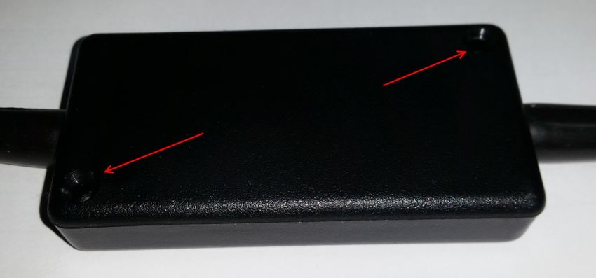
2021-08-19                                                           GCU7 Manual

Contents

Contents ........................................................................................................................................................ 2
I.     GENERAL OPERATING GUIDE ................................................................................................................ 3
II.    CONNECTING TO THE GCU.................................................................................................................... 3
III. UPGRADING THE FIRMWARE ................................................................................................................ 5
IV. GAUGES OVERVIEW .............................................................................................................................. 6
V.     GEARBOX & CAN CONFIG...................................................................................................................... 7
a.     H-PADDLE SHIFTER ACTUATORS SETUP .............................................................................................. 10
b.     H-PADDLE SHIFTER ACTUATORS SETUP - ADVANCED ........................................................................ 12
VI. INPUTS & SENSORS ............................................................................................................................. 15
VII. UP-SHIFT.............................................................................................................................................. 18
VIII. DOWN ................................................................................................................................................. 23
IX. CLUTCH................................................................................................................................................ 26
X.     MISC .................................................................................................................................................... 29
XI. SEQUENTIAL GEARBOX – QUICKSTART ............................................................................................... 32
XII. H PATTERN GEARBOX – QUICKSTART ................................................................................................. 34
XIII. SETTING UP DRIVE BY WIRE ................................................................................................................ 37
XIV. TUNING - UP SHIFT .............................................................................................................................. 38
XV. TUNING - DOWN SHIFT ....................................................................................................................... 40
XVI. FREQUENTLY ASKED QUESTIONS AND TROUBLESHOOTING .............................................................. 42

          2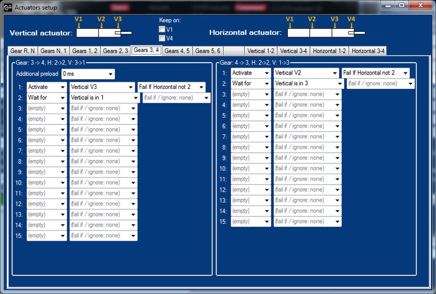
2021-08-19 GCU7 Manual
I. GENERAL OPERATING GUIDE
- In order to shift from Neutral to 1st, you need to press clutch + N/R button + paddle up. Clutch
and N/R checking can be deactivated in the software, but we do not recommend it. There’s
always a chance that someone would accidently touch the paddle while the car is running,
causing the car to start driving without driver control.
- Similarly, when shifting from 1st to Neutral (or Neutral to Reverse), you need to press clutch +
N/R button + paddle down. Again, Clutch and N/R button can be deactivated in the software.
- In H pattern mode, pressing the clutch + N/R button for 3 seconds restores the gear to neutral
from any position (even if invalid)
- For H pattern, synchromesh mode (with clutch actuator), to shift from neutral to 1st, you need to
press brake and shift up. When you release the brake, car will start moving.
II. CONNECTING TO THE GCU
GCU7 uses CAN BUS to connect to the computer so special interface is needed.
GCU Interface uses FTDI drivers which are usually already installed by default. If you’re having detecting
USB device, go to FTDI site and download the VCP drivers for your OS.
If you have USB CAN 3 and GCU with LED diode (on the side), you don't need to do anything else. CAN
Interface port is high speed (CAN FD) and is already terminated so you just need to connect the
connector. All GCU shipped after March of 2020 have LED on the side.
For GCU without the LED connector, follow the instructions below:
Each CAN BUS must be properly terminated (by 100-120 ohm resistor) on each side.
If you’re connecting to a car that already has a CAN BUS, nothing is really needed, because your CAN
BUS is already properly terminated. You just need to connect the CAN+ and CAN- to existing line and
that’s it.
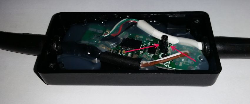
If your car does not have CAN BUS or you’re only connecting the GCU7 on a test bench, you need to
insert a jumper in the GCU interface to successfully connect to the GCU.
3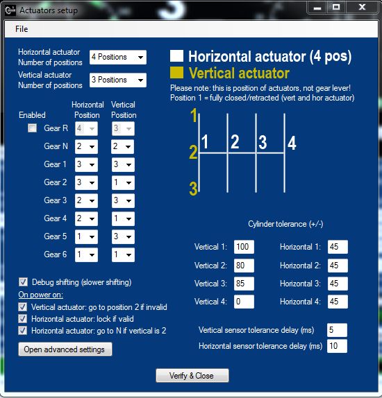
2021-08-19                                   GCU7 Manual

Remove the two screws:

Insert a jumper:

Please note: all GCU interfaces come with jumpers installed so if you’re connecting to the existing CAN
BUS, you need to remove the jumper.

         4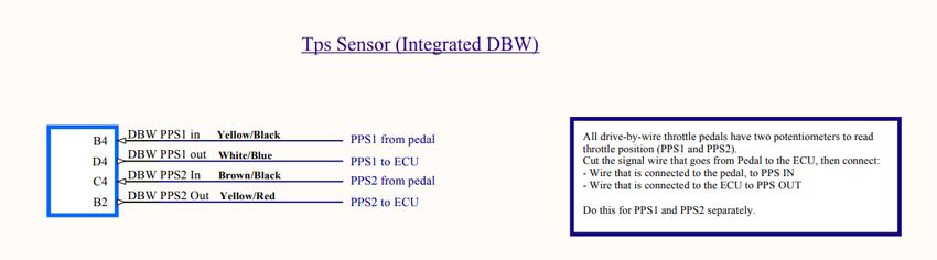
2021-08-19 GCU7 Manual
III. UPGRADING THE FIRMWARE
Please note that firmware and software are published together and they must match. If they do not
match, serious problems can occur so always make sure the version of the firmware and software is the
same!
Steps to upgrade the firmware:
- Download and run the new software
- Wait for the device to connect and read the settings from the device. Make sure you wait for all
the settings to load!
- Save the settings to a file, let’s call this file “before.dat”
- Open upgrade window, click open and select firmware .bin file (that matches the version of the
software)
- Click connect to device and turn the device off and on so device is found and is ready to
upgrade.
- Once it’s connected, click write new firmware and wait for it to finish.
- Turn the device off and on, wait for the settings to finish loading, then open the “before.dat” file
using the file->load settings and send new settings to the GCU. After the upgrade, all outputs are
disabled due to safety reasons, so you need to send the settings to the GCU to activate them
back.
- Turn the device off/on and enjoy the new firmware
5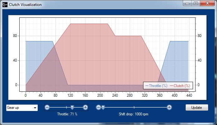
2021-08-19                                    GCU7 Manual

IV.          GAUGES OVERVIEW

RPM
RPM Gauge shows number of RPM.
Below the RPM you will see current wheel speed (only if wheel speed sensor is enabled) along with the
ideal (calculated) rpm according to the gear ratio, rpm and final drive. Clutch slip % is also shown.

GEAR POSITION SENSOR - GPS
Gear position sensor as the GCU sees it. Green field represents a gear and the range where gear is valid.
Gear ranges are only used if GCU is in “Sequential” mode. In H-Paddle Shifter mode, gear position is
calculated based on the position of the actuators & shifting direction. GPS value under the gauge is
degrees and raw value of the position sensor in the brackets.
If vehicle speed is enabled, you will find detected speed under the RPM along with the calculated rpm
based on the current gear.

THROTTLE POSITION SENSOR – TPS
0 - 100% of the throttle pedal pressed.
If Integrated DBW is selected you will also see voltages for PPS1 & PPS2 (below the gauge)

AIR PRESSURE
Air pressure in bar if air pressure transducer is used, otherwise only simulated number is shown
(minimum pressure from the compressor tab)

CURRENT GEAR
Gear which the gearbox is in. Total shifts is number of shifts since the last counter reset. Counter can be
reset by pressing the RST button next to the gear.

INPUTS & OUTPUTS
Status of each input and output. If active, it’s marked with green box.

TESTS
By pressing one of the buttons it manually triggers the command. Please note that UP and DOWN
actuators are only available when Sequential Gearbox is used.

         6
2021-08-19 GCU7 Manual
V. GEARBOX & CAN CONFIG
Please note: if any parameter is changed, settings must be sent to the GCU (Settings – send to GCU or
Send Changed to GCU - F5) in order to take effect.
GEARBOX
There are currently two types of gearboxes supported. Sequential & H-Paddle Shifter (Synchro /
Dogbox).
Gearbox Type: Sequential
This is regular sequential gearbox with up/down movement. Only two valves (1 two way actuator) is
used in this configuration.
Gearbox type: Type: H / Synchro or H / Dogbox
H-Paddle is MME Motorsport actuator assembly that controls 8 valves and shifts any H pattern. For
more H-Paddle Shifter options see H-Paddle Shifter actuators.
Number of forward gears is in the Number of gears dropdown.
Reverse
Defines if gearbox has reverse gear or not.
Mid neutral
If gearbox with neutral between the 1 and R is used (like Sadev ST75), this option is used to allow the
GCU to shift only partially. See MISC for setting up the neutral.
72021-08-19 GCU7 Manual Gear ratios Gear ratio for each gear. GCU will calculate the safe RPM for each gear, according to max engine RPM under the Down tab. See Downshifting for more info. FD is final drive ratio and is currently only used for if speed sensor is enabled. Can be ignored in most of applications. CAN BUS Enable to use CAN BUS support. Power to the GCU must be cycled if CAN BUS is enabled (and was previously disabled). If CAN BUS speed is unknown, 500 Kbps and 1000 Kbps are common values in automotive industry. GEAR POSITION SENSOR Gear position sensor is only available in Sequential mode. There are 3 types of Gear Position Sensor available. Type: Potentiometer This is standard 3 pin potentiometer found on almost every sequential gearbox. When this type is selected, GCU pin A2 must be connected to analog 0-5V sensor. This sensor must first be calibrated. See GEAR CALIBRATION below. Type: CAN Reads the gear position from CAN BUS. This sensor must first be calibrated. See GEAR CALIBRATION below. Type: RM22 This is SSI sensor found in one of the older designs. It is now absolete. CAN Device If gear position is connected to the ECU and your ECU supports sending the value to the CAN BUS, select the ECU you have. If your ECU is not in the list, please contact us with car info and ideally CAN BUS dataset so we include this in the software & firmware. Gear calibration In sequential mode, gears must be calibrated. By clicking Calibrate it will walk you through all of the gears and store the values for each gear in the boxes next to the gear. Numbers in boxes are values (0- 1024) where gear is detected. You should shift up & down few times to see if the range is correct and adjust accordingly. Second box next to a gear is the window in which this gear is still valid. Alternative to the calibration is to just shift to a desired gear and press “
2021-08-19                                   GCU7 Manual

H-PADDLE ACTUATORS
Only used if GCU is in H-paddle Shifter mode.
Window shows the position of each actuator (H = horizontal, V = vertical). Before first use (or if
actuators seem off), actuators need to be configured and calibrated. Click Setup configure the gearbox
shifting pattern (which way is reverse, 1st – 6th gear and so on), actuator tolerance and other H-Paddle
Shifter actuator related parameters and then Calibrate and follow the instructions. You can calibrate
the actuators using the Test button too. For more info on setup, see H-PADDLE-SHIFTER ACTUATOR
SETUP
If H/V sensors are incorrectly wired, you can swap them in the software by checking the Swap H/V
sensors.

Test window is used to verify the valve connections and allows you to turn on/off individual actuator
valve or test programmed patterns.

         9
2021-08-19 GCU7 Manual
a. H-PADDLE SHIFTER ACTUATORS SETUP
This screen can be opened by clicking the Setup button on GENERAL/SENSORS tab in H-Paddle Shifter
actuator region.
Before configuring the shift patterns, make sure your Number of gears parameter is correct
(GENERAL/SENSORS)
For each gear you need to set the position of each actuator.
Vertical actuator (See shift pattern image) usually has 3 positions. Position 1 is fully closed, Position 2 is
half-way open, Position 3 is fully opened.
102021-08-19 GCU7 Manual
Horizontal actuator can have 2, 3 or 4 positions, depending on number of gears and shift pattern.
Position 1 is fully closed.
On power on options allow to set up what actions are taken when you power up the gcu. Vertical
actuator: go to position 2 if invalid will move the vertical actuator to position 2 if position on power up
is not in the middle (2), completely out (3) or completely in (1). This allows you to always start with a
neutral gear if car stops somewhere “in between”. Horizontal actuator: lock if valid means that we lock
horizontal actuator from moving on power on if it’s in correct position (either 1, 2, 3 or 4 – depending on
the number of positions). This allows you to have direct shift ready when you start the car. If this
actuator is not locked, when shifting, GCU will run 3 commands, first it will move to neutral, then it will
move horizontal actuator in desired gear position and lastly, it will move vertical actuator to “in gear”
position. Horizontal actuator: go to N if vertical is 2 will move the horizontal actuator to N position if
vertical is middle (neutral) position and lock horizontal position.
Cylinder tolerance allows to set how much +/- of each position is still valid. For most applications, 60 is
ok. Depending on selector wear or free-travel of each gear this will have to be adjusted.
Typical value: 60 for the vertical and 50 for horizontal.
Vertical/Horizontal sensor tolerance sets how much time (in milliseconds) particular sensor needs to be
in position to treat it as “stable”.
112021-08-19 GCU7 Manual
b. H-PADDLE SHIFTER ACTUATORS SETUP - ADVANCED
General operation for H pattern:
- Before doing any modification of the procedures, make sure mechanical actuator travel is
correctly set and that mechanical linkages are working so they can shift correctly. Calibration of
positions must be performed using Test window and basic moves should be done and verified by
manually opening the valves and testing the POS 1, POS 2.. buttons (Test window)
- There are 3 valves in the vertical actuator. V1 is valve that activates the first chamber, V2 is
second chamber, V3 is the last chamber. Activating V3 will move the cylinder completely in. V2
will move the cylinder completely out. V1 in theory, should move the cylinder to middle
position, however – because of the very high speed that our valves reach, activating the V1 will
overshoot the rod. To overcome this, we first actuate the V1, then after a while we activate the
V3 that blocks the overshoot. This all has to be timed perfectly, otherwise the shift will not be
successful.
Similar to this, when going back from position 3 (completely out), to position 2, we first activate
V1. Because rod is already completely out, rod will not move. We only move the chamber piston
and hold it there. After some time, we activate the V3 which pushes the rod back to the middle
position (remember, V1 blocks the rod to go further back).
Horizontal actuator is the same, but has smaller diameter and has 4 shorter chambers.
122021-08-19 GCU7 Manual
- There are 6 tabs that have procedures for direct gear shifts, that is Gear RN/NR, N1/1N, 12/21, ..
56/65. There direct procedures are only used when last gear was successful and horizontal
actuator is locked. Locked horizontal actuator means that there are valves open that prevent the
horizontal actuator to move. If shift is not successful, all valves are closed and next shift happens
using different rules: Vertical 1-2, 3-4 and Horizontal 1-2,3-4.
After the unsuccessful shift (or after horizontal actuator not being locked) we do 3 phase
shifting:
Phase 1 - vertical actuator goes to neutral. Depending on where the actuator currently is, moves
to position to either from 3 or from 1. Procedures for these moves are defined in Vertical 1-2
and 2-3. Position 1 means procedure when going to position 1, Postion 2 – Forward when going
to Position 2 while moving out (forward) and Position 2 – Backward when going to Position 2
while moving in (backward).
If vertical actuator is already in middle position, we skip this phase.
Phase 2 – horizontal actuator moves to correct position defined by the gear pattern. Similar to
vertical, there are different procedures depending on where the current position is and where it
has to go to.
Phase 3 –vertical actuator moves to correct position defined by the gear pattern. Again, there
are different procedures depending on where the current position is and where it has to go to.
Valve procedures:
Each procedure line has 3 different selectors.
1 – Command
2 – Parameter
3 – Condition
Command and Parameter:
For command you have 2 options: Activate, Deactivate, Wait for.
Activate/Deactivate – activates/deactivates the valve defined by the parameter selector.
Wait for – waits for whatever is specified by the parameter selector:
- Fixed: 5-100ms – fixed delay
- % of Distance to P – gcu will wait for the position to reach specified percentage of move
towards P. For example, if we are in Position 1 and we activate V1 (meaning we are going
towards position 2), setting 50% of distance to 2 would mean that gcu waits until actuator is
in the middle (50%) between 1 and 2. Please note that valve that gets activated/deactivates
last defines which actuator we wait for. For example: if we do Activate H horizontal V2, this
means that Wait for will wait for horizontal actuator.
132021-08-19 GCU7 Manual
Condition:
If condition specified by the selector is met, procedure will fail with error. Please note that these
conditions are checked before command is executed.
142021-08-19 GCU7 Manual
VI. INPUTS & SENSORS
UP/DOWN input
Switches C1/C3
Paddles are connected to the C1 and C3 inputs. Switches need to close to ground when active. To limit
false triggering you can add Filter (ms) in milliseconds. Entering 50 here would mean that switch needs
to be stable for the duration of 50ms (must not switch on and off) before it is detected as a full press.
MME HCU: if MME hand controls are used, this needs to be selected.
Swapping the paddles can be enabled by checking the Swap paddles.
NEUTRAL SENSOR
It is recommended that Neutral sensor is enabled and working. It acts as a safety so you don't accidently
shift to neutral from first (or to reverse!) in a race or accidently shifting up while car is running
unattended (warming up).
Type: Switch E2
Switch is connected to E2 input. Switch needs to close to ground when active.
Type: MME PDU
Switch is connected to wireless control using MME PDU and configured there.
Type: MME HCU D1-D8
If using MME hand controls, this is where you define which button on the steering wheel is used as a
neutral. Make sure the button is properly configured in the HCU configurator. It should be a momentary
switch.
152021-08-19 GCU7 Manual
CLUTCH SENSOR/SWITCH
This switch is activated when clutch is pressed, either manually or automatically. For most applications,
Type: Switch D2 is used. If switch is on, when it should be off (mechanically), you can Invert it.
If switch is disabled, switch is always off so every function in the system that counts on it, will fail.
Duration in milliseconds specifies how long we wait for the sensor to stabilize.
If MME Clutch Actuator is used, type should always be MME CA/CCU.
Typical value: 5 ms
TACHO SENSOR
There are two types of TACHO sensors supported.
Type: Pulse
This is standard 0-12V pulse generated by the ECU. See ECU pinout for your car.
When this type is selected, GCU pin M4 must be connected to the corresponding pin on your ECU.
Type: CAN
Reads the RPM from CAN BUS.
CAN Device
If CAN is enabled select the ECU you have. If your ECU is not in the list, please contact us with car info
and ideally CAN BUS dataset so we include this in the software & firmware.
Pulses / Rev
This is where you select how many cylinders you car have. This also depends on the tacho output of your
ECU so try few options if RPM reading is off.
Not used if CAN is used.
Pulses / Rev – Custom
If you car has unsupported TACHO pattern or is strangely off, you can enter a factor here.
Not used if CAN is used.
THROTTLE POSITION SENSOR – TPS
There are two types of TPS readings available
Type: Potentiometer
This is standard 3 pin potentiometer found on almost every car. When this type is selected, GCU pin B1
must be connected to analog 0-5V sensor. This sensor must first be calibrated. See TPS CALIBRATION
below.
Type: CAN
Reads the TPS value from CAN BUS. No calibration is needed.
Type: Integrated DBW
This option is only supported in GCU versions that have 2 CAN BUS connectors and a LED indicator on
top. These GCU can control the DBW directly. See wiring.
162021-08-19 GCU7 Manual
CAN Device
If CAN is enabled select the ECU you have. If your ECU is not in the list, please contact us with car info
and ideally CAN BUS dataset so we include this in the software & firmware.
TPS calibration
TPS sensor must first be calibrated. TPS sensor is calibrated in a way that user presses and releases the
pedal and GCU stores the sensor value and calculates the % of pedal press.
To start, click the CALIBRATE button and follow the instructions. Press the throttle & click the button
again, then release it and click the button again. Don’t forget to send the data to the GCU.
BRAKE SENSOR
Brake sensor is only used with MME Clutch Actuator (CA) and is not needed in most applications.
Type: Switch C2
Switch is wired to C2 pin and must be closed to ground when active. If sensor is on when it should be
off, you can check the Inverted option.
WHEEL SPEED SENSOR
Enable this if you have wheel speed sensor install (Not needed in most of applications).
AIR PRESSURE SENSOR
Type: No sensor (external switch)
This option is used if you have pressure switch installed on the bottle. All MME bottles come with
pressure switch installed.
Type: 10 bar ratiometric (0.5 – 4.5V)
Analog pressure transducer should be connected to pin A1. Sensor should read 0.5V at 0 bar and 4.5V at
10 bars.
EXTERNAL CUT INPUT SENSOR
External cut input sensor is used as additional trigger that instructs the GCU to cut the ignition.
Please note that this is not the Ignition cut output (pin G2).
An example of external cut input would be if your ECU only has 1 input for ignition cut and you have
GCU configured to send the Ignition cut output to that pin and you still want to use the cut sensor on
the gear lever. When you manually shift (using the gear lever) GCU will detect this move and send the
cut signal to the ECU. This way you can configure fast closed loop shift even if the ecu doesn't support it.
Type: Switch C2
Switch is connected to C2 pin. Switch must close to ground when active.
If sensor is on when it should be off, you can check the Inverted option.
172021-08-19 GCU7 Manual
REVERSE SENSOR
Reverse sensor is a separate switch that identifies the reverse gear and should not be used on a gearbox
that has gear potentiometer and that potentiometer shows the reverse (most gearboxes are like that)
Type: Switch C2
Switch is wired to C2 pin and must be closed to ground when active. If sensor is on when it should be
off, you can check the Inverted option.
VII. UP-SHIFT
Please note: if any parameter is changed, settings must be sent to the GCU (Settings – send to GCU or
Send Changed to GCU - F5) in order to take effect.
Allow shift N to 1: If disabled, the only way to shift from neutral to 1st, is by hand. If in H-Paddle Shifter
mode to shift to 1st gear, beside this switch enabled, clutch button must also be pressed.
Typical value: Disabled in Sequential mode, Enabled in H-Paddle Shifter mode
Allow shift from R to N: if disabled, the only way to shift from reverse to neutral, is by hand.
Typical value: Disabled in Sequential mode, Enabled in H-Paddle Shifter mode
N/R Required from N->1: if enabled, the only way to shift to 1st gear is by holding the N buton while
pressing the up paddle.
Typical value: Disabled in Sequential mode, Enabled in H-Paddle Shifter mode
Before the shift:
Min between shifts: the time in milliseconds allowed between shifts.
Typical value: 150 ms
182021-08-19 GCU7 Manual
Delay after cut: how many milliseconds after we cut the power, we actually shift. Please note that this
parameter excludes the Actuator preload. If you want to use delay after cut, actuator preload must be
set to zero.
Typical value: 0 ms
Actuator preload: how many milliseconds before the cut, we start the shift. Air valves usually need
around 20ms to fully open, so we can preload the actuator before cutting. Use higher value if pipes to
the valves are longer. Please note that this parameter excludes delay after cut. If you want to use
actuator preload, delay after cut must be set to zero.
Typical value: 15 ms for dogbox.
During shift:
Switch UP/DOWN ports (sequential only): if checked, up and down output ports are swapped.
Restore power after (deg): This option allows you to return the power before the gear is completely in.
If this option is used, it’s very important that the engine ECU takes care of the soft power return
(gradually applying the full power). This way UP shift can be much smoother with shorter cut.
Typical value: 0 degrees.
Close throttle instead of CUT: If checked, instead of cutting the coil supply or sending “cut” signal, GCU
will close the throttle (only available if MME TBC or GCU DBW is used).
Cut over CAN: If enabled, you GCU will send the cut signal to various supported devices. If your device is
not listed, let us know.
After shift:
Keep in gear after shift (ms): how many milliseconds after the gear is engaged, we’re still pushing in.
Typical value: 50 ms
Keep cut after shift: how many milliseconds after the gear is engaged, we’re still cutting the power.
Typical value: 0 ms
Lever return actuator: one some sequential gearboxes, when actuators are mounted, the return spring
is too soft to return the gear lever back into the position. What this does is it pushes the actuator back
for specified milliseconds. Only used in Sequential mode.
Typical value: 10 – 15ms if return is slow in sequential mode.
Shift timeout: how many milliseconds we wait for shift to be finished. If gear is not engaged in this
period, all the actuators are unlocked and power is restored.
Typical value: 500ms in dogbox, 1500 in synchro
192021-08-19 GCU7 Manual
Auto retry (on failed shift): if shift is not successful, this option allows the GCU to shift again once again.
If shit is not successful the second time, shift will fail. Not recommended in sequential mode and should
be disabled.
Typical value: Disabled.
202021-08-19 GCU7 Manual
Autoshift:
Autoshift Mode: Defines the mode used. See below.
Activate after (rpm): After which RPM, Autoshift becomes active. RPM must be over this value to start
and, when active, If the rpm drop below this rpm, Autoshift is stopped. Please note that this is NOT the
rpm where GCU will shift the gear. That is defined in Autoshift at. Only used with 2 stage Autoshift.
While TPS over (%): This is the minimum TPS that needs to be set in order for the Autoshift to work. If
TPS drops below this value, Autoshift stops.
Autoshift at (rpm): At which RPM GCU will shift up.
Activate after 2nd gear: If this option is enabled, shifting 1-2 is done manually by the driver and
Autoshift will only work in 2-3 and higher. Only used with 3 stage Autoshift.
Autoshift Mode: 3 Stage
In order to use this mode, ECU must support launch control. GCU (Pin G1) will send »Launch« request to
the ECU and ECU input must be configured that when this happens, ECU goes into the launch mode
(Limit the RPM)
Procedure to start:
- Holding Autoshift button for more than 2 seconds, activates the Launch control. GCU sends active low
(ground) signal to the ECU via G1. ECU Must be able to enter Launch state. LED will be blinking slowly.
- While still holding the Autoshift button, we accelerate to a point that we don't need the Launch mode
anymore to accelerate freely (car gets enough grip to be able to push 100% throttle)
- We release the button and GCU deactivates the Launch mode (Pin G1), turning the Launch mode inside
the ECU off. LED is blinking faster.
- GCU will autoshift to the next gear when RPM is higher or equal to Autoshift at (rpm). If Activate after
2nd gear is enabled, it will only shift when in 2nd or higher gear. Driver needs to shift to 2nd gear in this
case manually by the paddle.
- Autoshift will continue to shift for as long as TPS is higher than While TPS over (%) and Paddle
up/down is not pressed. If TPS drops under the While TPS over (%) or up/down is pressed by the driver,
Autoshift will stop. LED is turned off.
212021-08-19 GCU7 Manual
Autoshift Mode: 2 Stage
Procedure to start:
- Driver must turn the autoshift mode on with the autoshift switch. It’s important that this switch is
toggle (fixed position) and not momentary type. LED will turn on.
- When RPM is over the Activate after N rpm & While TPS is over %, autoshift mode is activated. LED
will be flashing.
- When RPM reaches the specified Autoshift AT rpm, it will automatically shift up. LED will still be
flashing.
- If throttle is below While TPS over (%) or if paddle up/down switch is pressed, auto shift is
automatically disabled. LED will be off.
- To turn on the auto shift mode driver must switch the autoshift off and on again.
Autoshift Mode: Rally: up shift only
- Autoshift switch must be on. LED will be on.
- When RPM is over or equal than Autoshift at (rpm) & throttle is higher or equal than While TPS is
over % it will automatically shift up.
- If Autoshift switch is deactivated, autoshift is disabled.
External cut:
External cut enabled: If enabled it allows to cut the engine via external switch. For this option, external
swith should first be configured on INPUT & SENSORS
Wait for new gear and turn off: If enabled, cut will be active for as long as the gear is not engaged, but
not more than Max duration. If this option is disabled, cut will be active for fixed time, Max duration.
Typical value: Enabled.
Use strain gauge (pin B3), treshold: if this option is enabled, voltage on B3 pin will tell the GCU to shift if
voltage is over the treshold. Please note that voltage here is represented with a 10 bit value, so 0 = 0V
and 1024=5V. You can see current voltage in digital form next to the treshold window.
Max duration: Specifies the maximum duration of engine cut. Also see External cut - Wait for new gear
and turn off
Typical value: 600 ms.
222021-08-19 GCU7 Manual
VIII. DOWN
Please note: if any parameter is changed, settings must be sent to the GCU (Settings – send to GCU or
Send Changed to GCU - F5) in order to take effect.
Allow shift 1 to N: If disabled, the only way to shift from 1st to Neutral is by hand. If in H-Paddle Shifter
mode to shift to Neutral gear, beside this switch enabled, clutch & neutral button must also be pressed.
Typical value: Disabled in sequential mode, Enabled in H-Paddle Shifter mode.
Allow shift N to R: If disabled, the only way to shift from Neutral to Reverse is by hand. If in H-Paddle
Shifter mode to shift to Reverse gear, beside this switch enabled, clutch & neutral button must also be
pressed.
Typical value: Disabled in sequential mode, Enabled in H-Paddle Shifter mode.
Max engine RPM: Specifies the maximum rpm engine is allowed to reach after a downshift. Exact
downshift rpm is calculated based on a gear and gear ratio (see GENERAL/SENSORS). Which is the
calculated rpm is shown for each gear in the boxes below.
Example: If Max RPM for your engine is 6300 rpm and your second gear ratio is 3.571, GCU calculates
the Downshift if under rpm for second gear is 3928. What this means is that in second gear, you will not
be allowed to shift over 3928 rpm. If you’d shift down in second to first over 3928 rpm, in you would
reach more than 6300 rpm in 1st gear which is more than Max Engine RPM is.
Blip over CAN: If enabled, GCU will send the blip signal to various supported devices. If your device is
not listed, let us know.
232021-08-19 GCU7 Manual Before the shift: Disable shift if TPS > %: If throttle is applied (more than Disable shift if TPS >) we don’t want to allow downshift. Typical value: For a dogbox Disable shift if TPS > 20 Min between shifts: the time in milliseconds allowed between shifts. Typical value: 150 ms Disable shift to R if wheel speed > 1km/h: if checked, the only way to shift to reverse is if car is not moving. Only used if wheel speed sensor is enabled. Typical value: unchecked Queued downshift: If Enabled, GCU will allow the gears to be queued if RPM is too high or If Throttle is over degrees. What this does is it allows the driver to preselect the desired gear while pushing the throttle. When throttle is released and “safe” rpm is reached, GCU will automatically downshift. The harder you brake, the faster GCU will downshift. Typical value: Throttle is over 90 %, RPM is too high disabled. Throttle blip: Blip enabled: Enables throttle blip actuator. Throttle blip must be connected to GCU Pin J3. See wiring diagram. If MME Throttle Body Controller or Integrated DBW is used you can specify just how much you want to blip the throttle (Blip amount), otherwise this option is disabled and you need to set the travel mechanically. If MME TBC is used, you can set custom % for each gear using the Custom % for each gear. Typical value: Enabled on a dogbox, Enabled on synchro with DBW. Disable blip if RPM
2021-08-19                                      GCU7 Manual

Max blip duration: Specifies what the maximum throttle blip duration is (in milliseconds). Even if
specified degrees are not reached, GCU stops the throttle blip.
Typical value: 100 ms.

Close blip in ms: how many milliseconds does it take to close the blip (ramp). Only used with MME TBC
module.
Typical value: 0 ms.

After throttle blip:

Delay before activating valve: how many milliseconds after the throttle blip is closed we activate the
downshift actuator.
Typical value: 20 ms.

During shift:

Cut during shift: if checked, GCU will cut the ignition during movement of the actuator.
Switch UP/DOWN ports (sequential only): if checked, up and down output ports are swapped.

After shift:

Keep in gear after shift (ms): how many milliseconds after the gear is engaged, we’re still pushing in.
Typical value: 50 ms

Lever return actuator: one some sequential gearboxes, when actuators are mounted, the return spring
is too soft to return the gear lever back into the position fast enough. What this does is it pushes the
actuator back for specified milliseconds. Only used in Sequential mode.
Typical value: 10-15 ms.

Cut after successful shift: the time in milliseconds we cut the power after the shift is complete.
Typical value: 30 ms

Downshift timeout: how many milliseconds we wait for shift to be finished. If gear is not engaged in this
period, all the actuators are unlocked and power is restored.
Typical value: 500ms in dogbox, 1500 in synchro

Auto retry (on failed shift): if shift is not successful, this option allows the GCU to shift once again. If
shit is not successful the second time, shift will fail.
Typical value: Disabled.

      25
2021-08-19 GCU7 Manual
IX. CLUTCH
Driving bite point: After the shift, this is the position we call bite point and this is the position clutch will
go to. Start with the same value as starting bite point (make sure you learn it first). It’s easier to test it
when downshifting (blip should be turned off for this setup). If, when you down shift, car just doesn’t
want to synchronize and looks like the clutch is pressed more (for like 1-2 seconds, depending on the
max bite point duration setting) then suddenly jerks, it means this value is too high. Do it in -10 steps.
Increase it if immediately, after the shift, car jerks too much. How fast the clutch ramps to the bitepoint
is defined in milliseconds with Bitepoint ramp (ms).
Release in Neutral: If enabled, clutch will be released when you shift to neutral.
Don't release if brake is pressed: If enabled, clutch will be pressed when brake is applied in neutral gear
and release when brake is off (if release in N is checked)
Driving speed (km/h): this is the speed that defines that the car is driving normally. This speed is also
used as a treshold for the antistall algorithm. If speed drops below this speed and brake is applied,
antistall procedure will start.
Upshift:
Close throttle at clutch X in Y ms: When clutch engaging and it reaches X percent, throttle closes in Y
milliseconds. This allows smooth transition of clutch/throttle. Duration is only available if TBC module is
used.
Bite point duration per 1000 rpm at 100% throttle: Duration in milliseconds that we hold the clutch at
bite point. This duration depends on how much the rpm difference between current and target gear is
and how much throttle is applied.
Example: value = 100ms, shifting from 2nd to 3rd gear, at 5000 rpm, at 100% throttle, drops us to 3000
rpm. RPM difference is 2000 rpm which means total bite point duration is 200ms. If we did the same at
262021-08-19 GCU7 Manual 50%, this value would be 400ms. You can use Show clutch helper diagram to see diagram of the parameters entered. Stop bite point when rpm diff
2021-08-19                                     GCU7 Manual

Starting off:

Starting bite point point: For the first time and after some time, it’s advised to learn the bite point. This
is done by pressing Learn button. Procedure to learn the bite point:
- put the car in first gear and press the brake (clutch should be fully in)
- click Learn button
- release brake
- clutch will start to move slowly. As soon as you feel the car changing noise/moving, press the brake
again.
- this is it. No other actions needed. You can experiment with few different “feeling points” to get
optimal result.

Stop bite point when rpm diff
2021-08-19                                     GCU7 Manual

Antistall:

If Enabled antistall will trigger automatically in specified Ramp (ms) if wheel speed drops below the
Driving speed (km/h) and brake is applied. If brake is not applied,antistall is disabled. Antistall is not
possible without Starting off enabled.

X.           MISC

Please note: if any parameter is changed, settings must be sent to the GCU (Settings – send to GCU or
Send Changed to GCU - F5) in order to take effect.

LOGGING
Leave it Enabled if you want to use GCU logging features.

SHIFT LIGHT
If Enabled GCU will activate the output F1 (active low) if current engine rpm is higher than RPM. See
wiring diagram for more info.

REVERSE ACTUATOR
Enable reverse actuator: if enabled, GCU pin F2 will be used as a reverse actuator. This means that
when you shift to reverse, GCU will not shift up/down actuators, but separate, reverse actuator
connected to pin F2.

INTEGRATED DBW
Read throttle from HCU: if checked, GCU will try to read throttle position from Hand Control Unit (HCU)
and override the throttle if it's higher than the manual (foot) throttle. See SETTING UP DRIVE BY WIRE.

      29
2021-08-19 GCU7 Manual
CUT (PWM)
If »Enable partial GCU« is checked and coils are wired over the M2 and M3 pins, whenever cut is active,
GCU will toggle the coil supply in specified PWM frequency with PWM duty cycle. When cut is
deactivated, PWM duty cycle ramp returns to 100% in PWM duty recovery ramp.
You can specify if you want partial cut only for specific gears by selecting coresponding checkbox.
If gear shift is not successful after Full cut after milliseconds, we go to full (100%) cut. If Full cut after is
0, this option is disabled.
Only gears that have Enabled checked will do partial cutting. Enabling partial cut for 2nd gear means
that partial cutting will be active when going from 2 to 3. Gears that are not checked, will just do full cut.
After Full cut after milliseconds if gear has not engaged yet, GCU will go to full cut mode. Set to 0 ms to
disable this option.
Example:
PWM frequency: 100hz, PWM duty cycle: 50%, PWM duty recovery ramp: 50ms
When cut is active, GCU will toggle power supply 100 times in one second, with 50% time on and 50%
time off (PWM duty cycle 60% would mean 60% on, 40% off). When cut is deactivated, duty cycle
returns to 100% (100% on) in 50ms.
DISPLAY
Send to device over CAN: If this is enabled, GCU will output can bus dataset with gear, rpm, button
pressed etc. If MME Motorsport DASHBOARD is used, this is the dataset that is broadcasted to the bus:
CAN2.0B, 11 bit, 8 bytes. 16 bit values sent high byte first (MSB)
BASE ID: 1983
DLC: 8
BYTE 0: gear number [0-8], 8 being reverse.
BYTE 1: air pressure. To get pressure in bar you need to divide it with 10.
BYTE 2: active switches [B0 – up sw, B1 – down sw, B2 – clutch sw, B3 – auto sw, B4 – N switch, B5 – ext cut sw,
B6 – brake sw, B7 – reverse sw]
BYTE 3+4: engine rpm
BYTE 5: active outputs [B0 – autoshift on, B1 – autoshift led on, B2 – cut on]
BYTE 6: error number [0 – no error, 1 – gear not reached, 2 – incorrect gear reached, 3 – unknown gear, 4 –
timeout waiting, 5 – cylinder not in correct position, 6 – throttle too high, 7 – shift too early, 8 – pressure too low, 9
– shift from NR not allowed, 10 – shift from 1N not allowed, 11 – rpm too high, 12 – neutral not detected, 13 –
clutch not released in time, 14 – clutch not pressed, 15 – clutch not detected]
BYTE 7: free
Blink gear over RPM: It’s possible for the GCU to blink the gear when over certain RPM.
302021-08-19 GCU7 Manual
MID NEUTRAL
When enabled (see GENERAL under GEARBOX) it allows the GCU to shift partially to neutral between 1
and R. It does this by pulsing the valve, while checking if the gear is neutral or has moved for more than
Stop after GPS moves degrees. Pulse is the amount of time valve is open, Max tries is how many times
we activate it and Delay between tries is the duration before we do another cycle (valve is closed during
this time). If needed, you can enable Different parameters for R->N to have different parameters for R-
N. To slow down the actuator, it's also possible to hold UP+DOWN valve for UP+DOWN ON duration and
then turn UP off after UP OFF delay. Similary, for RN, you can first activate reverse (already in reverse so
no movement is allowed) for the duration of Hold in R before RN and then release the reverse before
shifting to N.
Typical value: Pulse: 8ms, Max tries: 5, Delay: 450ms, Stop after gps moves: 10
NEUTRAL LIGHT
When Activate E3 when in N is active, output on E3 will be active when in neutral.
312021-08-19 GCU7 Manual
XI. SEQUENTIAL GEARBOX – QUICKSTART
Please note: if any parameter is changed, settings must be sent to the GCU (Settings – send to GCU or
Send Changes to GCU - F5) in order to take effect.
After successfully connected to the GCU7 (green bottom bar in the software), go to the
GENERAL/SENSORS tab and:
• Select GEARBOX Type to Sequential.
• Under GEARBOX Function, Select Standalone if you want the GCU to take care of the cutting,
blip signal and every other operation needed to shift. If you have Engine ECU capable of
complete paddle shifting logic, use Ext. Logic. Please note: if you only do the cutting with Engine
ECU, you still need the Standalone, because GCU7 will still need to send a signal to cut.
• Adjust NEUTRAL SENSOR and CLUTCH SENSOR accordingly. If you will shift with the paddles
from N->R, R->N, N->1 or 1->N you need to enable this switch. For more info setting the clutch
sensor see GENERAL/SENSORS in chapter II.
• Verify that all connected inputs are working correctly. In the top right corner you can see if
GCU7 sees the signals. Inputs to look for and: UP paddle, DOWN paddle, Neutral*, Clutch*.
• Verify the UP, DOWN, BLIP and Ignition CUT outputs by pressing the output tests. Please note
that if you're using engine ECU to do Ignition CUT and Blip, you need to connect wires G2
(White/black) for the Ignition CUT and J2 (Yellow/Pink) for the throttle blip and configure them
accordingly in the ECU software. They're active low which means that they close to ground
when they're active.
• Enter number of gears and gear ratios in the GEARBOX group and go to DOWN tab and adjust
the Max engine RPM parameter. This is the absolute maximum engine rpm you will able to
reach when downshifting. Go back to the GENERAL/SENSORS tab.
• If you use pressure sensor (usually not the case), enable the AIR PRESSURE SENSOR and enter
max sensor pressure. Currently, we only support 4-20 mA sensors (connected to GCU7 pin A1).
• Adjust TACHO SENSOR and TPS, including the TPS Calibration process if needed (Calibrate
button). Make sure the RPM and TPS are working properly. For more info see
GENERAL/SENSORS in chapter II.
• Under GEAR POSITION SENSOR click the Calibrate button and follow the instructions to
calibrate the position sensor. What this will do is it will ask you to go through all gears and store
the position to each gear. You can then adjust the tolerance or gear position values for each
gear by entering the number of degrees in the dropdown. Clicking on the < next to the gear will
store current gear position value into the field.
322021-08-19 GCU7 Manual
Go to UP tab and:
• Adjust Allow shift from N to 1 and R to N accordingly.
• Put these to 0: Delay after cut, Keep cut after shift, Don’t cut if TPS2021-08-19 GCU7 Manual
XII. H PATTERN GEARBOX – QUICKSTART
Please note: if any parameter is changed, settings must be sent to the GCU (Settings – send to GCU or
Send Changed to GCU - F5) in order to take effect.
After successfully connected to the GCU7 (green bottom bar in the software), go to the
GENERAL/SENSORS tab and:
• Select GEARBOX Type to H-Pattern. If you have our clutch actuator and this is synchromesh
gearbox, choose H / Synchromesh, otherwise H / Dogbox.
• Under GEARBOX Function, Select Standalone if you want the GCU to take care of the cutting,
blip signal and every other operation needed to shift. If you have Engine ECU capable of
complete paddle shifting logic, use Ext. Logic. Please note: if you only do the cutting with Engine
ECU, you still need the Standalone, because GCU7 will still need to send a signal to cut.
• Adjust NEUTRAL SENSOR and CLUTCH SENSOR accordingly. If you will shift with the paddles
from N->R, R->N, N->1 or 1->N you need to enable this switch. If you’re using clutch actuator,
clutch sensor has to be enabled and Type set to MME CA/CCU.
• Verify that all connected inputs are working correctly. In the top right corner you can see if
GCU7 sees the signals. Inputs to look for and: UP paddle, DOWN paddle, Neutral*, Clutch*.
• Verify the Ignition CUT, Blip (if present) outputs by pressing the output tests.
• Enter number of gears and gear ratios in the GEARBOX group and go to DOWN tab and adjust
the Max engine RPM parameter. This is the absolute maximum engine rpm you will able to
reach when downshifting. Go back to the GENERAL/SENSORS tab.
• If you use pressure sensor (usually not the case), enable the AIR PRESSURE SENSOR and enter
max sensor pressure. Currently, we only support 4-20 mA sensors (connected to GCU7 pin A1).
• Adjust TACHO SENSOR and TPS, including the TPS Calibration process if needed (Calibrate
button). Make sure the RPM and TPS are working properly. For more info see
GENERAL/SENSORS in chapter II.
Go to UP tab and:
• Adjust Allow shift from N to 1 and R to N accordingly.
• Put these to 0: Delay after cut, Keep cut after shift, Don’t cut if TPS2021-08-19 GCU7 Manual
Under DOWN tab:
• Adjust Allow shift from 1 to N and N to R accordingly.
• Adjust the Max engine RPM parameter. This is the absolute maximum engine rpm you will able
to reach when downshifting.
• Disable: Allow partial shift, Queued downshift and Autoretry on failed shift.
• Enable Blip and set Max blip duration to 150ms. If you have MME TBC, put 30% into Amount
and leave the custom % for each gear unchecked.
• Set Delay before activating the valve to 10ms.
• Set the Disable blip if RPM to 1000 for a synchromesh or 3000 for a dogbox and Close blip to
0ms. If you use MME TBC, you can also adjust the blip % for each gear. Good value for every
gear to start is 30%. Uncheck if MME TBC is not used.
• Set Cut with blip + max cut duration to 50 ms
• Set Blip until barrel moves (deg) to 27 degrees.
• Leave Rev match unchecked.
• Set Keep in gear after shift to 100ms.
• Set Lever return actuator to 0ms.
• Set Cut after successful shift to 50ms.
• Set Downshift timeout to 500ms for a dogbox, otherwise 1500ms if you have synchromesh
gearbox.
Under COMPRESSOR tab:
• Enable the Compressor.
• Adjust Start only if engine running accordingly.
• Set Compressor control via to External switch.
352021-08-19 GCU7 Manual
Under CLUTCH tab:
• Leave the Enabled unchecked and skip this chapter if you have a dogbox, otherwise leave it
checked.
• Under Starting off: Set Starting PID to 0.1, 0.1, 0 and PID2 to 0.1, 0.1, 0. Stop bitepoint when
rpm diff to 100, Release duration at 100% throttle to 1500. Clutch actuator needs to be
configured before continuing. Put the car in first gear and press brake, clutch should be pressed
by the actuator. If it is not, do not continue. If clutch is pressed, while holding the brake, press
the Learn button and release the brake. Clutch should start moving slowly. Once your car starts
to change noise, press the brake again. Bite point is now learnt (this value is read only so the
only way to see it is to load the settings from the GCU and it change). Send the settings to the
GCU and try releasing the brake, car should start moving. For more info about setting the PID for
starting off, see CLUTCH.
• Set Driving bite point to 100 less than the starting bite point. To properly tune this value see
CLUTCH.
• Under Upshift: set Close throttle at clutch to 30 % in 0ms, Bite point duration per 1000 rpm at
100% throttle to 0, Stop bite point when rpm diff to 200, Release duration at 100% throttle to
1000, Restore throttle at clutch to 90 %. See CLUTCH for more info on setting these later on.
• Under Downshift: set Start blip at clutch to 20%, Bite point duration per 1000 rpm to 2000,
Stop bite point when rpm diff to 200, Max bite point duration to 2000 and Release duration
per 1000 rpm to 500. See CLUTCH for more info on setting these later on.
362021-08-19 GCU7 Manual
XIII. SETTING UP DRIVE BY WIRE
Before starting, you need to identify the potentiometer wires on the pedal. On most cars there are 2
potentiometers (even 3 in some cases).What you need to do is put the GCU in the middle of the pedal
and ECU so GCU is able to control blip the throttle automatically.
From the GCU’s wiring diagram:
After you set the TPS/Type to Integrated DBW and if everything is connected properly, you should see
voltages under the TPS gauge:
There are 2 versions possible:
- First one is V1/V2 where V2 is 2xV1. It’s important that in this configuration V1 is lower than
V2. If it’s the other way around, you need to switch the wires so you get correct reading.
- Second one is V1/V2 where V2 is inversed V1. If V1 is 0.5, then V2 is 4.5V. When you press
the pedal, V1 increases, while V2 decreases. Again, V1 needs to be smaller than V2.
If it’s the other way around, you need to switch the wires so you get correct reading.
After you have the wiring set, you need to calibrate the throttle. You do this by pressing the CALIBRATE
button and following the instructions. Once everything is finished, make sure you send the settings to
GCU (F5) and you can try testing the blip. TPS should move with the pedal. You can do blip test by
pressing the Blip actuator test button. The duration and amount of the blip when clicking the test
button is defined by Max blip duration (ms) and Blip amount %.
For tuning the blip, see TUNING – DOWN SHIFT
372021-08-19 GCU7 Manual
XIV. TUNING - UP SHIFT
GCU has datalogging capabilities that allow you to capture all shifting events. Logs can be accessed using
menu Log/Read full data from GCU or using Log manager and download each session. As these logs
tend to get huge, we recommend reasing the log before testing the parameters & then downloading the
log. Downloaded logs require additional Megalogviwer software to be installed. Software can be
downloaded here: https://www.efianalytics.com/MegaLogViewer/download/
You should always verify the parameters with datalogging.
For upshift to be successful, there are 2 most important factors:
- Engine cut is agressive enough to do fast torque reduction
- Delaying the shift so engine has time to unload the gearbox properly
Here's an example of incorrectly tuned up shift:
You can see that after pressing the paddle (white), shift actuator (yellow) is activated which immediately
starts pushing the gearbox barrel forward (green). Because cut happens too late (red), gearbox is
struggling with the shift and barrel doesn't move which means the gearbox is unable to change gears
because the engine has not reduced the power enough. At 75% of the cut duration, gear engages which
means that engine has reduced the torque enough.
382021-08-19 GCU7 Manual
There are 2 parameters that define how fast actuator is activated.
First one is Delay after cut (ms) and second Actuator preload (ms).
Actuator preload 10ms means that we first move the actuator and then start the cut after 10ms, while
Delay after cut 10ms means we cut for 10ms and then move the actuator.
Both at 10ms for example means no delay. We cut immediately when we activate the actuator.
If we go back to the example, just by removing the Actuator preload (setting it to 0) and adding 75ms
delay after cut, makes things much better. 75ms is the amount of time current ECU cut strategy needs to
unload the gearbox:
Another important factor are ECU settings. It's very imprtant that there are no fixed durations and that
ECU cut is set so cut is active for as long as GCU has the cut signal active.
Most cars work best at around 90% ignition cut + ignition retard. How much retard is needed depends
on the car. Values from 10 to 20 degrees work best.
Example of perfect up shift:
392021-08-19 GCU7 Manual
XV. TUNING - DOWN SHIFT
GCU has datalogging capabilities that allow you to capture all shifting events. Logs can be accessed using
menu Log/Read full data from GCU or using Log manager and download each session. As these logs
tend to get huge, we recommend reasing the log before testing the parameters & then downloading the
log. Downloaded logs require additional Megalogviwer software to be installed. Software can be
downloaded here: https://www.efianalytics.com/MegaLogViewer/download/
You should always verify the parameters with datalogging.
For down shift to work correctly, here is an order of events that must follow to make the shift as smooth
as possible:
- Throttle blip is activated. It should be long and big enough to get the engine to respond with
the “wuf”. Blip amount (TPS %) and Max blip duration are the parameters that define this.
25% and 100ms is a good starting point. It should not rev too much, just enough so it
transfers the torque from negative (gearbox pushing the engine) to positive torque (engine
pushing the gearbox)
- In the moment blip is closed (when positive torque is being transferred to negative), we
must start the shift. When shift starts is defined by Delay before activating. 50ms is good
start.
402021-08-19 GCU7 Manual
Example of good down shift:
Here you can see that we add blip, then later on start the actuator. You can see that it takes some time
that engine reacts to the blip (red). You can see the amount of TPS it reaches (white).
The longer the downshift, the rougher will the shift be so you want to make the shift as fast as possible.
If there's too much throttle, engine will push the gearbox forward. One way of preventing this is to add
cut after the shift. In most cases, if blip is properly tuned. this is not needed.
412021-08-19 GCU7 Manual XVI. FREQUENTLY ASKED QUESTIONS AND TROUBLESHOOTING Can’t connect to the GCU If you see a red DISCONNECTED bar in the bottom it means that either USB CAN interface is not plugged in or you don’t have proper drivers installed. On Windows 7 and newer, drivers are automatically installed once you plugged in, but it could take up to 5 minutes from the to finish loading. If you have Windows XP you need to install the drivers from the drivers folder. If you see an orange CAN INTERFACE CONNECTED, WAITING FOR THE GCU bar in the bottom, it means that USB CAN interface is successfully detected and that you need to connect the GCU can bus. Reasons for GCU not responding: - GCU is not powered properly (L1 needs 12V and M1 needs GND) - CAN BUS speed is incorrectly set (You can change interface speed in top right corner) - CAN BUS is not properly terminated. If you’re connecting to the existing CAN BUS line, it’s a good chance that CAN BUS is already terminated, so you need to remove the jumper from the USB CAN Interface (See CONNECTING TO THE GCU). If GCU is not connected to an external CAN BUS line, USB CAN Interface needs to have the jumper inserted! To check if CAN BUS is properly terminated, remove the USB Interface from the USB port, power off all the devices (that are connected to the CAN BUS) and measure resistance between CAN+ and CAN-. Existing network should have reading between 50-60 ohms, while no CAN BUS should have 100 ohms (with jumper inserted). Please note that you need to measure with car turned off and usb interface disconnected from the USB PORT. I can shift up, but can’t shift down First, verify that paddles are correctly configured and detected (GENERAL/SENSORS). Most common reason is caused by TPS being incorrectly set up. GCU will prevent down shift if TPS is too high. How high it can be is configured by the Disable shift if TPS setting in the DOWN tab. Make sure you have TPS properly setup, correct TPS type selected (GENERAL/SENSORS) and calibrated. See GENERAL/SENSORS for more info. Second most common reason are Gearbox ratios (GENERAL/SENSORS - GEARBOX) & Max engine RPM (DOWN) being incorrectly set RPM sensor Blip works when I activate it from the software, but does not work when shifting First, make sure the blip is enabled (DOWN/Blip enabled checked). Blip will not work if RPM is lower than the number specified in DOWN/Disable blip if RPM
You can also read