FOR F-RAT AND POP-UP CBR-306 CIRCUIT BOARD - TECHNICAL DOCUMENTATION - ITOH DENKI
←
→
Page content transcription
If your browser does not render page correctly, please read the page content below
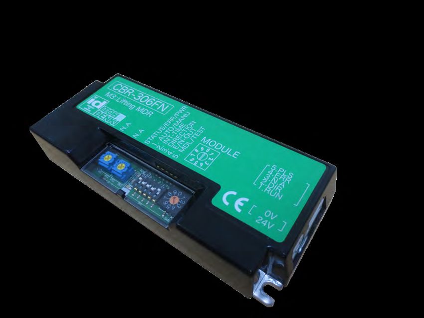
CBR-306 circuit board
for F-RAT and POP-UP

    Technical Documentation
solutions
Controls Motorized rollers Modules
Standard circuit board DC Brushless 90° transfer
HBR-605
CB016 CB016B F-RAT-S250 CBM-105
CBR-306
CBM-105 HBR-605
F-RAT-S300 CBM-105
External Integrated CBR-306
Replacing
CBK-109 CBK-109B CB030
circuit board circuit board CBK-109
CB016B
F-RAT-NX75 HBM-201
CB018 IB-E
IB-P
CBV-108
45° transfer
ZPA circuit board
CBM-105
POP-UP CBR-306
HB510 HB510B Ø50 Ø50
CBM-105
HBK-608 PM500 FE
B&W AS-i 3.0
HB510 PM500 XE Wenglor
IB-E
HBV-609 CBV-108 B&W AS-i 3.0
PM500 VE HBV-609 PM500 XP Wenglor
IB-P
PEPPERL-FUCHS
PM500 FE-B
CB016B PM500 XK AS-Interface
HB510B B&W AS-i 3.0
Module circuit board
PEPPERL-FUCHS
PM500 XC AS-Interface
Ø60,5 B&W AS-i 3.0
HBR-605
CBM-105
CBR-306 PM605 FE HB510
Ø60,5
IB-E
CBV-108 B&W AS-i 3.0
HBM-201 PM605 VE HBV-609 PM605 XE Wenglor
IB-P
B&W AS-i 3.0
PM605 FE-B
CB016B PM605 XP Wenglor
HB510B
Network controller
CBK-109
HBK-608
PM605 KT IB-P
IB-E IB-E
PM605 KT-B CBK-109B
IB-P
Ø32
PM320 HS CB018
Corresponding circuit board Compatible module / sensor Max load to be conveyed Mechanical brake version
CBR-306 FOR
Technical documentation
F-RAT AND POP-UP 2 Original notice - T1.8Summary
1. Presentation of the circuit board Page 4
General descritpion
Dimensions
General characteristics
2. Location of items Page 6
3. Wiring Page 6
Internal Circuit Diagram
Connector CN1 - Supply 24 VDC
Connector CN2 - Terminal 1 : Start / Stop (RUN)
Connector CN2 - Terminal 2 : Direction of rotation CW/CCW (DIR)
Connector CN2 - Terminal 3 : Not used
Connector CN2 - Terminal 4 : Error signal (ERR)
Connector CN2 - Terminal 5 : Impulse signal (PLS)
Connector CN3 - Motor connector
4. LED 1, LED 2 and LED 3 Page 11
5. Potentiometers VR1 and VR2 Page 11
6. Dip-switches configuration SW1 Page 12
Dip-switch 1 : Selection restart mode
Dip-switch 2 : Selection of downtime
Dip-switch 3 : Selection direction of rotation
Dip-switch 4 : Error signal
Dip-switch 5 : Selection test mode / Start
7. SW5 : selection transfer module Page 19
Annex 1 : Declaration of incorporation Page 20
CBR-306 FOR
Technical documentation
F-RAT AND POP-UP 3 Original notice - T1.81. Circuit board presentation
The CBR-306 circuit board is designed exclusively to drive motorized roller for lifting of transfer modules F-RAT
and POP-UP. It controls the raise/lower movement in complete safety, thanks to the impulse signal of the rotor
and the reception of the stop signal of the motorized roller.
General description
• Fastener hardware : - 2 cross-head screws M4 x 15
- 2 spring washers M4
- 2 nuts M4
• 1 connector WAGO 734-102 (2 points)
• 1 connector WAGO 733-105 (5 points)
The CBR-306 circuit board can be associated only with the M3 motorized roller for lifting, PM500FE Serie -
Speed Code 17.
M1
M2
Motorized roller
Motorized roller for for belt direction
transfer direction
M3
Motorized roller
for lifting
M3 For lifting
CBR-306F□ PLC, etc...
24VDC
Dimensions
129
120
STATUS/ERR/PWR
CBR-306F□
1. AUTO/MANU
3. DIRECTION
5.PLS
5. MDL/TEST
M3:Lifting MDR MODULE
4.5
2. INT-TIME
4.ERR
4. E/N-OUT
3.N.A
9 0 1 2.DIR
1.RUN
7 8
2 3
52
40
N.A
N.A
456
0V
24V
90 1
23
78
18
456
4.5
38.5 47
23
3
3
CBR-306 FOR
Technical documentation
F-RAT AND POP-UP 4 Original notice - T1.8General Characteristics
Directives applied EN 61000-2-2, EN 61000-6-4, EN 60529
TBTS 24VDC ± 10% - ripple < 10%
Power supply
Protection 6,3A
Absorbed current without motorized
0.03A
roller
Start current limitation 4A
SPECIFICATIONS
Motor start time after start signal
≤ 15 ms
(RUN / STOP)
Protection index IP20
Integrated fuse of 6,3A
Against polarity reversal 24V and 0V
Protection
Thermal protection (95°C for circuit board and 105°C for the motor)
Against induced overvoltage
Initialisation time after start signal ≤1s
Temperature range 0° ~ +40 °C
Relative humidity < 90% without condensation (Avoid thermal shocks)
Environment
Neither corrosive nor explosive atmosphere
Vibrations < 0,5 G
Start / Stop Motorized roller start and stop
Inversion of rotation direction by external command
Direction of rotation
Selection of motorized roller rotation direction by DIP switch
Module selection Module selection using a rotary switch
Without mechanical brake version : Dynamic braking
Braking and mechanical brake With mechanical brake version : Dynamic braking during 200ms then
FUNCTIONS
mechanical blocking.
Test mode Motorized roller for lifting forced start
Impulse signal 2 pulses per rotor rotation. Output signal in NPN.
Output signal PNP logic against thermal error, motor jam, low voltage,
Error signal
induced voltage, etc.
Power supply with green LED
Signalling Error with red LED
Number of errors produced with orange LED
Restart Auto / manual reset selection after thermal trip
Circuit board side Wire side
Wago 734-102 (10A max)
CONNECTORS
Power (CN1) Wago 734-162 (10A max) Conductor cross-section : 0,5 - 1,5 mm²
AWG 20~14
Wago 733-105 (4A max)
Control (CN2) Wago 733-365 (4A max) Conductor cross-section : 0,08 - 0,5 mm²
AWG 28~20
Motor (CN3) JST#S9B-XH-A male 9 pin for without brake version
CBR-306 FOR
Technical documentation
F-RAT AND POP-UP 5 Original notice - T1.82. Location of items
STATUS/ERR/PWR
CBR-306F□
1. AUTO/MANU
3. DIRECTION
5.PLS 5
5. MDL/TEST
M3:Lifting MDR MODULE 4 CN2
2. INT-TIME
4.ERR
4. E/N-OUT
3.N.A 3
9 0 1 2.DIR 2
CN3 1.RUN 1
7 8
2 3
N.A
N.A 456
0V 2
1
CN1
24V
90 1
23
78
456
VR1
9 0 1
VR2
7 8
2 3 4
6 5
LED1
9 pins version SW5
sans frein LED2 ON CN1 Supply connector 24VDC
LED3 CN2 Connector input / output control
1 2 3 4 5
CN3 Connector motor
LED1 Green LED supply
SW1
LED2 Red LED error
LED3 Orange LED
SW1 VR1 Potentiometer not used
1 Selection restart mode VR2 Potentiometer not used
2 Selection downtime 1 2 3
SW1 Dip-switches for configuration
4 5 6 7
3 Selection direction of rotation (CW/CCW) SW5 Rotary switch for selection transfer module
4 Selection error signal mode CN1
5 Selection test mode / Start +24V
1
2
0V
D
3. Wiring
Internal circuit diagram 24V
2 3 4 5 3
6 7 8
2
C 1
5V
CN1 3.3K
+24V
1 CN2 1 4
nRUN IN
1 2 3
RUN
2
0V DIR
2
3
Vin
4 5V
ERR
5
PLS
3.3K
1 4
nDIR IN
2 3
B
Vinput
24V 24V
PNP ERR OUT
3
2
A 1
PULSE NPN ERR OUT
Title
5V
Size Number
A3
CBR-306 FOR
Date: 14-Jan-2014
3.3K File: J:\PWB\SPBD\CBM-10
CN2 Technical documentation 1
1
2
4
3 4 5 6 7
F-RAT AND POP-UP 6
nRUN IN
RUN
1 2 3 Original notice - T1.8
2
DIR
3
VinConnector CN1 - Power supply 24VDC
• 24 VDC switch-mode power supply, which can accept an overcurrent
CN2
of 150% for 3 to 5 s, is recommended to optimize the supply power to
the number of motorized rollers to be controlled.
5.PLS 5
4 • The +24 VDC circuit is protected by a 6,3 A fuse.
4.ERR
3.N.A 3
2.DIR 2
1.RUN 1 Provide a power supply that is sufficiently powerful in function
of the type and number of motorized rollers to be powered.
0V 2 0 VDC
24V 1 24 VDC
CN1
Connector CN2 - Terminal 1 - Start / Stop (run)
PNP version : CBR-306FP NPN version : CBR-306FN
STATUS/ERR/PWR
CBR-306F□
CN2 CN2
1. AUTO/MANU
▶ ▶
3. DIRECTION
5.PLS5 Pulse signal 5.PLS 5 Pulse signal
5. MDL/TEST
Lifting MDR4
M3:4.ERR ▶ MODULE 4 ▶
2. INT-TIME
Error signal 4.ERR Error signal
4. E/N-OUT
3.N.A 3 Not used 0 3.N.A 3 Not used
2.DIR 2 ◀ 9 1
Direction of rotation 2.DIR 2 ◀ Direction of rotation
1.RUN 1 ◀ 1.RUN 1 ◀
7 8
2 3
Start / Stop Start / Stop
N.A
N.A
456
0V 2 0 VDC 0V 2 0 VDC
24V 1 24 VDC 24V 1 24 VDC
90 1
23
78
CN1 456
CN1
• START : contact closed
• STOP : contact open
• Input current : 3 mA max
• Motorized roller start time ≤ 15 ms
The 0V of CN2 must be common to the supply voltage of CN1-2.
When powering the circuit board, it is necessary to wait at least 1 s before giving the On command.
Do not use the 24 VDC circuit-breaker or the 24 VDC power-suppl y circuit-breaker to turn the
motorized roller “On/Off”. You must use Terminal 1 of the CN2 connector.
CBR-306 FOR
Technical documentation
F-RAT AND POP-UP 7 Original notice - T1.8Connector CN2 - Terminal 2 - Direction of rotation CW/CCW (DIR)
CN2 • The rotation direction is given in function of
dip-switch 3 of SW1
STATUS/ERR/PWR
□
1. AUTO/MANU
• Input current 3 mA max at 24 VDC
3. DIRECTION
5.PLS 5
5. MDL/TEST
MODULE 4
2. INT-TIME
4.ERR
4. E/N-OUT
3.N.A 3 • Time delay between CW and CCW : 0,5s
9 0 1 2.DIR
1.RUN
2
1 ◀ CW/CCW
7 8
2 3
N.A
456
0V 2
24V 1
90 1
23
78
456
CN1 ON
1 2 3 4 5
SW1
It is possible to invert the rotation direction during operation simply by opening or closing the contact on terminal
2 of CN2.
In the event of a change in the rotation direction using the “acceleration/deceleration” function, the motorized
roller will slow down then stop for 0.5s before starting to accelerate in the opposite direction of rotation.
Refer to the chapter «SW1-Dip-switch 3» for exact direction of rotation according to different criteria.
ON command (RUN)
CN2- terminal 1 ON
Closed Change direction command (DIR)
CN2- Terminal 2 Open
Stop of
0,5s
Direction of rotation CCW
Direction of rotation CW
Connector CN2 - Terminal 3 - Not used
CN2
STATUS/ERR/PWR
□
1. AUTO/MANU
3. DIRECTION
5.PLS 5
5. MDL/TEST
MODULE 4
2. INT-TIME
4.ERR
4. E/N-OUT
3.N.A 3
9 0 1 2.DIR 2
1
◀
1.RUN
7 8
2 3
N.A
456
0V 2 0 VDC
24V 1 24 VDC
90 1
23
78
CN1
456
CBR-306 FOR
Technical documentation
F-RAT AND POP-UP 8 Original notice - T1.8Connector CN2 - Terminal 4 - Error signal (ERR)
CN2
• 24 VDC error signal output by open collector 25 mA
STATUS/ERR/PWR
□ max to be adjusted in function of the programmable
1. AUTO/MANU
3. DIRECTION
5.PLS 5 logic controller using a resistor (not supplied) to be
5. MDL/TEST
MODULE 4 ◀ Error signal
2. INT-TIME
4.ERR
4. E/N-OUT
9 0 1
3.N.A 3
2
output added in addition to the integrated 100 Ω resistor.
2.DIR
1.RUN 1
7 8
2 3
N.A
456
0V 2
ON
24V 1 Sends a signal to Terminal 4 on CN2
90 1
when everything is normal.
23
78
CN1
456
ON OFF
Sends a signal to Terminal 4 on CN2
1 2 3 4 5 when there is a fault.
SW1
When powering off and on, the error signal is sent.
Do not consider this signal during 0.5s to power on, and 2s to power off.
We must adjust the resistance «R» so that the current «i» does not exceed 25mA.
24 24-2,5
25mA ≥ R≥
R+100 0,025
R ≥ 860Ω
In the event of a current ≥25 mA, there is a risk of damaging the transistor.
If output is connected to inductive load (Ex. Relay coil , solenoid , actuator , etc . ), make sure to protect
output from Back voltage with a free-wheeling diode.
CBR-306 FOR
Technical documentation
F-RAT AND POP-UP 9 Original notice - T1.8Connector CN2 - Terminal 5 - Pulse signal (PLS)
CN2
• Pulse signal output: NPN by an open collector requiring the
adjustment of the output voltage to 24 VDC max. and 25 mA
5 ◀
5.PLS
4.ERR 4
Pulse signal output max. using a resistor (not supplied) to be added in addition to the
3.N.A 3 integrated 100 Ω resistor.
2.DIR 2
1.RUN 1
0V 2 In case of a current ≥25 mA, there is a risk of damaging the
24V 1 transistor.
CN1
• 2 pulses per rotor turn.
• 5 μs time lag with the Hall effect sensor.
• The number of pulses per motorized roller turn is indicated in the
technical data as a function of the series and its speed code.
• Speed deviation : ±3%
• Number of pulses for PM500FE - Speed code 17 : 89,9 pulses per
motorized roller turn.
Voltage to be applied
(max 24VDC)
R (to adjust)
Pulse output (to PLC, etc...)
NPN Logic
Terminal 5
i ≤ 25mA
We must adjust the resistance «R» according to the «V»
100 Ω voltage applied so that the current «i» does not exceed 25mA.
V
25mA ≥
R+100
Example if V = 24VDC 24-2,5
R≥
0,025
CBR-306
R ≥ 860Ω
Connector CN3 - Motor connector
STATUS/ERR/PWR
CBR-306F□
1. AUTO/MANU
3. DIRECTION
5.PLS 5
5. MDL/TEST
CN3 M3:Lifting MDR MODULE 4
2. INT-TIME
4.ERR
4. E/N-OUT
3.N.A 3
9 0 1 2.DIR 2
1.RUN 1
7 8
2 3
• Without brake version : Motorized roller connector type JST# S9B-XH-A male 9 pins.
N.A
N.A
456
0V 2
24V 1
90 1
23
78
456
CBR-306 FOR
Technical documentation
F-RAT AND POP-UP 10 Original notice - T1.84. LED 1, LED 2 and LED 3
LED 1 (green)
STATUS/ERR/PWR
CBR-306F□ The indicator is lit when the circuit board is powered.
1. AUTO/MANU
3. DIRECTION
5.PLS 5
5. MDL/TEST
M3:Lifting MDR MODULE 4
2. INT-TIME
4.ERR
4. E/N-OUT
3.N.A 3
9 0 1 2.DIR 2
1.RUN 1
LED 2 (red)
7 8
2 3
N.A
N.A
456
0V 2 The indicator is lit when a malfunction has occurred
24V 1
90 1 and allows the type of fault to be identified.
23
78
456
LED 3 (orange)
4 differents states of LED allow identify number of
LED1
production error since the start-up. (see chapter
LED2 «Error signal»)
LED3
5. Potentiometers VR1 and VR2
VR1 - Not used
STATUS/ERR/PWR
CBR-306F□
1. AUTO/MANU
3. DIRECTION
5
5.PLS
VR2 - Not used
5. MDL/TEST
M3:Lifting MDR MODULE 4
2. INT-TIME
4.ERR
4. E/N-OUT
3.N.A 3
9 0 1 2.DIR 2
1.RUN 1
7 8
2 3
N.A
N.A
456
0V 2
24V 1
90 1
23
78
456
VR1
VR2
CBR-306 FOR
Technical documentation
F-RAT AND POP-UP 11 Original notice - T1.86. Dip-switches for configuration SW1
STATUS/ERR/PWR
CBR-306F□ 1. AUTO/MANU
3. DIRECTION
5.PLS 5
5. MDL/TEST
M3:Lifting MDR 2. INT-TIME MODULE 4.ERR 4
4. E/N-OUT
3.N.A 3
9 0 1 2.DIR 2
1.RUN 1
7 8
2 3
SW1 factory setting
N.A
N.A
456
0V 2
24V 1
90 1
ON
23
78
456
1 2 3 4 5
SW1
Dip-switch Function ON OFF
Automatic (the circuit board try
Manual (Restart after a new to restart without any external
1 Selection of restart mode
command on Run / Stop or Dir) intervention after the thermal
cooling)
2 Selection of downtime 0,5s 1,0s
Selection of rotation direction Change of CW or CCW rotation direction in function of the state of
3
CW / CCW Terminal 2 of CN2 (see chapter on the rotation direction).
Selection of error signal Signal sent to terminal 4 of CN2 Signal sent to terminal 4 of CN2
4
mode when everything is normal. when there is a fault.
Motorized roller level test in the high
5 Selection of test mode / Start Start of the transfer module
position
SW1 - Dip-switch 1 : Selection of restart mode
ON
Manual restart
STATUS/ERR/PWR
CBR-306F□
1. AUTO/MANU
3. DIRECTION
5.PLS 5
5. MDL/TEST
M3:Lifting MDR MODULE 4
2. INT-TIME
4.ERR
4. E/N-OUT
3.N.A 3
9 0 1 2.DIR 2
1 OFF
1.RUN
7 8
2 3
N.A
N.A
456
0V 2
Automatic restart
24V 1
90 1
23
78
456
ON Dip-switch 1 of SW1 allows to choose «Automatic» or «Manual»
restart mode after a thermal fault.
1 2 3 4 5
SW1
CBR-306 FOR
Technical documentation
F-RAT AND POP-UP 12 Original notice - T1.8SW1 - Dip-switch 1 : Selection of downtime
ON
0,5s
STATUS/ERR/PWR
CBR-306F□
1. AUTO/MANU
3. DIRECTION 5.PLS 5
5. MDL/TEST
M3:Lifting MDR MODULE 4
2. INT-TIME
4. E/N-OUT 4.ERR
3.N.A 3
9 0 1 2.DIR 2
1 OFF
7 8 1.RUN
2 3
N.A
N.A
456
0V 2
1,0s
24V 1
90 1
23
78
Appendix 1 .CBR-306F□ Detail
456
CBR-306F is a driver card for up/down motion.
ON Keep SW1-5 to be OFF.
MDR is driven by RUN signal input, but is
automatically stopped after counting Caution It cannot operate by external input signal, or may
cause a failure if SW1-5 is set to ON.
predetermined motor pulses.
1 2 3 4 5
SW1
Time Chart
It’s possible toup/down
● Normal select downtime
motion between the end of pulse counting corresponding to the motor rotation (See
chapter SW5) and the restart of motorized
ON roller for lifting.
This function allows to compensateOFFfor any accidental and random malfunction.
RUN signal input to CBR-306F
RUN
Lifting MDR
STOP Abnormal up/down motion
● Abnormal up/down motion
ON
RUN signal input to CBR-306F
OFF
Appendix 1 .CBR-306F□ Detail
Lifting MDR
RUN
STOP
Counting the specified Counting the specified
motor pulses motor pulses 1s or 0.5s
CBR-306F is a driver card for up/down motion.
Keep SW1-5 to be OFF.
MDR is driven by RUN signal input, but is
■ List of Functions
automatically stopped after counting Caution It cannot operate by external input signal, or may
【Wiring】 cause a failure if SW1-5 is set to ON.
predetermined motor pulses.
NPN signal input〔FN〕type PNP signal input〔FP〕type
④CN2
Time Chart Normal up/down motion
STATUS/ERR/PWR
CBR-306F□ CN2 CN2
1. AUTO/MANU
3. DIRECTION
● Normal up/down motion 5.PLS
5. MDL/TEST
M3:Lifting MDR MODULE
2. INT-TIME
4.ERR
4. E/N-OUT
3.N.A
9 0 1 2.DIR Motor pulse signal output Motor pulse signal output
1.RUN 5.PLS 5.PLS
7 8
2 3
ON 4.ERR Error signal output 4.ERR Error signal output
N.A
N.A
456
RUN signal input to CBR-306F
3.N.A 3.N.A
0V 2.DIR 2.DIR CW/CCW
OFF 24V 1.RUN CW/CCW 1.RUN
90 1 RUN/STOP RUN/STOP
23
78
RUN 0V 0V
456
⑤CN1 0V 0V
Lifting MDR 24V 24VDC 24V 24VDC
STOP
CN1 CN1
Not used ①SW1 ⑥SW5
● Abnormal up/down motion
③PWR LED ③ERR LED ③STATUS LED ※CN2#3(N.A) is not used. ※CN2#3(N.A) is not used
ON
RUN signal input to CBR-306F
OFF
Description ON OFF Default Remarks
Auto/manual recovery
RUN selection with thermal,
1 Manual rec. Auto rec. ON Ref. Error detail, cancellation
Lifting MDR low voltage, induced voltage error
STOP
Counting the specified Counting the specified
2 Stop holding time motor pulses 0.5sec 1sec
motor pulses OFF 1sRefer
Ref. Time chart ● or 0.5s
to abnormal lifting operation
① SW1
3 Rotation direction selection (Ref. rotation dir. change) OFF (Normally set to OFF)
(DIP switch)
4 Alarm (error) signal output selection Normal time output Error time output OFF Ref. E rror signal output
■ List of Functions Keep SW1-5 to be OFF.
5 Forcible RUN 【Wiring】
RUN Module selection Caution
It cannot operate by external
OFF input signal, or may cause a
NPN signal input〔FN〕type PNP signal
failureinput〔FP〕type
if SW1-5 is set to ON.
④CN2
STATUS/ERR/PWR
CBR-306F□ Color Indication CN2 Remarks CN2
1. AUTO/MANU
3. DIRECTION
5.PLS
5. MDL/TEST
M3:Lifting MDR MODULE
2. INT-TIME
4.ERR
4. E/N-OUT
PWR LED Green 9 0 1Indicates powered
3.N.A
2.DIR
condition Motor pulse signal output Motor pulse signal output
1.RUN 5.PLS Ref. Error detail, canceling method 5.PLS
③
7 8
2 3
Error signal output Error signal output
ERR LED Red Indicates error type 4.ERR 4.ERR
N.A
N.A
456
CBR-306 FOR
3.N.A 3.N.A
0V 2.DIR 2.DIR CW/CCW
Indicates number of error occurrence form1.RUN CW/CCW
STATUS LED Technical
orange documentation 90 1
24V
Refer to CB-016 User Manual
RUN/STOP
1.RUN
RUN/STOP
F-RAT AND POP-UP thermister
⑤CN1 13 0V
reaction, motor stall or under voltage
Original 0V
notice - T1.8
23
78
0V
456
0V
24V 24VDC 24V 24VDC
No. Description Remarks
CN1 CN1SW1 - Dip-switch 3 : Selection of direction of rotation
CN2
The rotation direction of a motorized
STATUS/ERR/PWR
CBR-306F□
1. AUTO/MANU
roller is defined in function of the
3. DIRECTION
5.PLS 5
5. MDL/TEST
M3:Lifting MDR MODULE 4
2. INT-TIME
4.ERR
4. E/N-OUT
3.N.A 3
9 0 1 2.DIR
1.RUN
2
1 ◀ CW/CCW rotation direction selection associated
7 8
2 3
with dip-switch 3 of SW1, with an open
N.A
N.A
456
0V
24V
2
1 or closed contact on terminal 2 of CN2
90 1
and the series of the motorized roller.
23
78
CN1
456
ON
The «OFF» position must be set for the start-up of
F-RAT and POP-UP
1 2 3 4 5
SW1
PM500FE series
ON
5.PLS 5 SW1
MODULE 4.ERR 4
3
1 2 3 4 5
3.N.A
9 0 1 2.DIR
1.RUN
2
1 ◀ CW/CCW
7 8
2 3
456
0V 2
1 ON
24V
90 1
SW1
23
78
456
1 2 3 4 5
ON
5.PLS 5 SW1
MODULE 4.ERR 4
3
1 2 3 4 5
3.N.A
9 0 1 2.DIR
1.RUN
2
1 ◀ CW/CCW
7 8
2 3
456
0V 2
24V 1 ON
90 1
SW1
23
78
456
1 2 3 4 5
Do not invert rotation direction using SW1-3 during rotation.
To change rotation direction when using SW1-3, it is essential that the motorized roller be first stopped.
CBR-306 FOR
Technical documentation
F-RAT AND POP-UP 14 Original notice - T1.8SW1 - Dip-switch 4 : Error signal
ON
CN2 Signal sent to terminal 4 of CN2
when everything is normal.
STATUS/ERR/PWR
CBR-306F□
1. AUTO/MANU
3. DIRECTION
5.PLS 5
5. MDL/TEST
M3:Lifting MDR MODULE 4
2. INT-TIME
4.ERR Error signal
4. E/N-OUT
3.N.A 3
9 0 1 2.DIR 2
1.RUN 1 OFF
7 8
2 3
Signal sent to terminal 4 of CN2
N.A
N.A
456
0V 2
90 1
24V 1 when there is a fault.
23
78
456
CN1
Do not consider the error signal
LED1 for 0.5s after switching on, and 2s after
ON
LED2 switching off the power supply to the
1 2 3 4 5
circuit board.
LED3
SW1
Identification of defects in LED 1, LED 2 and LED3
LED 1
Led off Led on
LED 2
Led on 1 flash per seconde 6 flashes per seconde
Led off Blocking / overload Insufficient input voltage
Thermal fault
motor fault
An order must be given on terminal CN2-2 (direction of rotation) to initialize the fault history.
LED 3
Led off Led on 1 flash per seconde 6 flashes per seconde
The error occurred two time
(Different error that the
The error occurred for the The error occurred two first)
The error occurred one
third time time
time The error occurred three time
(Series of same error) (Same error that the first)
(Same error that the first
and the second)
An order must be given on terminal CN2-2 (direction of rotation) to initialize the fault history.
CBR-306 FOR
Technical documentation
F-RAT AND POP-UP 15 Original notice - T1.8Error signal
input CN2-4
LED 1 SW1-4 SW1-4 Motorized Cause / Motorized roller
OFF ON roller Error signal reset
symptom restart
LED 2 condition
No Signal
N.A.
signal sending
No No Standard start-up.
Stopped No power Connect the 24 VDC power supply.
signal signal See chapter 5.
Signal No Circuit board Remove power then replace the circuit Standard start-up.
Stopped
sending signal damaged board. See chapter 5.
Automatic restart (SW1-1 OFF)
1 minute after drops below the thermal trip threshold, the motorized roller
restarts immediately
1 minute after drops below the thermal trip threshold, the injection
signal RUN STOP RUN on terminal 1 of CN2 removes the error
signal and restarts the motorized roller at the same time.
Injection signal RUN
1 minute after drops below the thermal trip STOP RUN on terminal
Signal No threshold, injection signal RUN STOP 1 of CN2
Stopped Thermal fault
sending signal RUN on terminal 2 of CN2
Automatic restart in 1 minute
Manuel restart (SW1-1 ON)
1 minute after drops below the thermal trip threshold, the injection
signal RUN STOP RUN on terminal 1 of CN2 removes the error
signal and restarts the motorized roller at the same time.
After drops below the thermal trip threshold, Injection signal RUN
injection signal RUN STOP RUN on STOP RUN on terminal
terminal 2 of CN2 1 of CN2
Signal No Connector CN3 Remove power and properly connect the Standard start-up.
Stopped
sending signal disconnected motorized roller. See chapter 5.
The motorized Injection signal RUN STOP RUN on terminal 1 of CN2 to reset and
roller restart.
Signal No
Stopped is jammed Injection signal RUN
sending signal Injection signal RUN STOP RUN or STOP
for more than STOP RUN on terminal
4 seconds. (*) RUN STOP on terminal 2 of CN2
1 of CN2
Automatic restart (SW1-1 OFF)
Secure the supply voltage above 18VDC. Immediate restart
Manuel restart (SW1-1 ON)
Input voltage
Signal No Secure the supply voltage above 18VDC. Then the injection signal
Stopped insufficiente
sending signal RUN STOP RUN on terminal 1 of CN2 removes the error signal and
(Led 2 Led 3 Led 2 Led 3
Appearance State Appearance State
(Red) (Orange) (Red) (Orange)
0 Normal First time Insufficient input voltage
First time Blocking / Overload motor Second time Insufficient input voltage
Second time Blocking / Overload motor Third time or more Insufficient input voltage
Third time or more Blocking / Overload motor First time Thermal fault
First time Blocking / Overload motor Second time Thermal fault
Second time Blocking / Overload motor Third time or more Insufficient input voltage
Third time or more Thermal fault First time Thermal fault
First time Blocking / Overload motor Second time Insufficient input voltage
Second time Thermal fault Third time or more Thermal fault
Third time or more Blocking / Overload motor First time Thermal fault
First time Blocking / Overload motor Second time Insufficient input voltage
Second time Thermal fault Third time or more Insufficient input voltage
Third time or more Thermal fault First time Insufficient input voltage
First time Thermal fault Second time Thermal fault
Second time Blocking / Overload motor Third time or more Thermal fault
Third time or more Blocking / Overload motor First time Insufficient input voltage
First time Thermal fault Second time Thermal fault
Second time Blocking / Overload motor Third time or more Insufficient input voltage
Third time or more Thermal fault First time Insufficient input voltage
First time Thermal fault Second time Insufficient input voltage
Second time Thermal fault Third time or more Thermal fault
Third time or more Blocking / Overload motor First time Blocking / Overload motor
First time Thermal fault Second time Thermal fault
Second time Thermal fault Third time or more Insufficient input voltage
Third time or more Thermal fault First time Blocking / Overload motor
F t time
irs
Blocking / Overload motor Second time Insufficient input voltage
Second time Blocking / Overload motor Third time or more Thermal fault
T d time or more
hir
Insufficient input voltage First time Thermal fault
First time Blocking / Overload motor Second time Blocking / Overload motor
Second time Insufficient input voltage Third time or more Insufficient input voltage
Third time or more Blocking / Overload motor First time Thermal fault
First time Blocking / Overload motor Second time Insufficient input voltage
Second time Insufficient input voltage Third time or more Blocking / Overload motor
Third time or more Insufficient input voltage First time Insufficient input voltage
First time Insufficient input voltage Second time Blocking / Overload motor
Second time Blocking / Overload motor Third time or more Thermal fault
Third time or more Blocking / Overload motor First time Insufficient input voltage
First time Insufficient input voltage Second time Thermal fault
Second time Blocking / Overload motor Third time or more Blocking / Overload motor
Third time or more Insufficient input voltage
First time Insufficient input voltage
Second time Insufficient input voltage
Third time or more Blocking / Overload motor
CBR-306 FOR
Technical documentation
F-RAT AND POP-UP 17 Original notice - T1.8SW1 - Dip-switch 5 : Selection of Test mode / Start
ON
STATUS/ERR/PWR
CBR-306F□ Test mode allows to adjust the level of the
1. AUTO/MANU
3. DIRECTION
5.PLS 5
5. MDL/TEST
M3:Lifting MDR MODULE 4
2. INT-TIME
4.ERR
4. E/N-OUT
9 0 1
3.N.A
2.DIR
3
2 upstream and downstream conveyor. To do this,
1.RUN 1
powering on the circuit board and set SW1-5 to
7 8
2 3
N.A
N.A
456
0V
24V
2
1
«ON».
90 1
23 The transfer part rises slowly and automatically
78
stops in the high position.
456
OFF
ON Start of transfer module selected with SW5.
1 2 3 4 5
SW1
«Test mode» is used to adjust the level of upstream and downstream conveyor from the transfer table. To do
this, select the type of module installed with SW5 (see section 7 - «SW5 - Selection of transfer module»), switch
on the module and set SW1-5 to «ON».
The transfer table rises to half the normal speed and automatically stops in the high position without sending the
signals to the CN2-1 (on / off) and CN2-2 (direction of rotation) terminals.
ON
SW1#5
OFF
RUN
Lifting MDR
STOP Counting a prescribed
motor pulse
«Switch on» allows the circuit board to receive signals at terminals CN2-1 (On / Off) and CN2-2 (Direction of
rotation).
It is absolutely necessary to put the «OFF» position before starting the transfer module.
CBR-306 FOR
Technical documentation
F-RAT AND POP-UP 18 Original notice - T1.87- SW5 : Selection of transfer module
The motorized roller for lifting stops automatically
CBR-306F□ STATUS/ERR/PWR and independently of the stop signal of CN2-1, at
1. AUTO/MANU
3. DIRECTION
5
5.PLS
the end of counting down the number of pulses.
5. MDL/TEST
M3:Lifting MDR 2. INT-TIME MODULE 4.ERR 4
4. E/N-OUT
3.N.A 3
9 0 1 2.DIR
1.RUN
2
1 If the CBR-306 circuit board receives the stop
7 8
2 3
signal before the countdown is complete, the
N.A
N.A
456
0V 2
90 1
23
24V 1 motorized roller stops when the order is received.
78
456
ON
9 0 1 CN1 Start/Stop signal
OFF
7 8
2 3 4
5 6
Motorized roller RUN
Default factory for lifting STOP
setting of SW5
Pulses
SW5 Type of transfer The number of pulses which gives the stop position of the motor roller for
Not used, lifting depends on the type of transfer module and selection is made using
0 SW5.
the motor is disabled
1 F-RAT-S, POP-UP
2 F-RAT-T225 In case of improper selection, this may cause malfunction and damage
3 F-RAT-U225 the equipment.
Not used,
4-9
the motor is disabled
CBR-306 FOR
Technical documentation
F-RAT AND POP-UP 19 Original notice - T1.8Annex 1
Incorporation declaration
in accordance with the EC Machinery Directive 2006/42/EC, Annex II B
The manufacturer :
ITOH DENKI CO., Ltd
1146-2 Asazuma-Cho, Kasai, Hyogo 679-0105 Japan
Distributed in Europe by:
ITOH DENKI Europe SAS
490 avenue des Jourdies - PAE les Jourdies - BP 323
74807 St Pierre en Faucigny Cedex - France
hereby declares that the product series:
Circuit board CBR-306
is an incomplete machine as defined in the EC Machinery Directive and therefore does not fully meet
the requirements of this Directive. Service entry is prohibited until the whole machine/system in which
it is incorporated is declared to be in compliance with the EC Machinery Directive.
The health and safety requirements of Annex I have been applied. The special technical documents in
accordance with Annex VII have been drawn up (and, if appropriate, submitted to the competent authorities).
Person authorized to compile the technical documentation :
Toshiyuki TACHIBANA
ITOH DENKI CO., Ltd
1146-2 Asazuma-Cho, Kasai, Hyogo 679-0105 Japan
ITOH DENKI EUROPE SAS
Masayuki SHIMODA
490 Avenue des Jourdies, 74800 St Pierre en Faucigny - France
EC Directives applied :
• Machinery Directive 2006/42/EC
• European EMC Directive 2014/30/EC
• European RoHS Directive 2011/65/EU
ITOH DENKI EUROPE SAS, undertakes to forward, following a duly motivated request from the national
authorities, the relevant information concerning the quasi-machine.
Saint Pierre en Faucigny, 19 July 2021
T. AKASHI, General Director
CBR-306 FOR
Technical documentation
F-RAT AND POP-UP 20 Original notice - T1.8Technology for tomorrow
ITOH DENKI
490 Av. des Jourdies - P.A.E. les Jourdies
74800 St Pierre en Faucigny - France
Phone : +33 (0)4 50 03 09 99 Fax : +33 (0)4 50 03 07 60
www.itoh-denki.comYou can also read