FATBOY RT Owner / Operator's Manual - Models F1026 F1030 F1036 - Meyer Manufacturing
←
→
Page content transcription
If your browser does not render page correctly, please read the page content below
PB-FATBOY

                    FATBOY RT
                   Models F1026 • F1030 • F1036

                 Owner / Operator’s Manual

 5 / 2021             Starting 2020 Model Year
6990633 (1-13)                  Printed in U.S.A.   © Bobcat Company 2013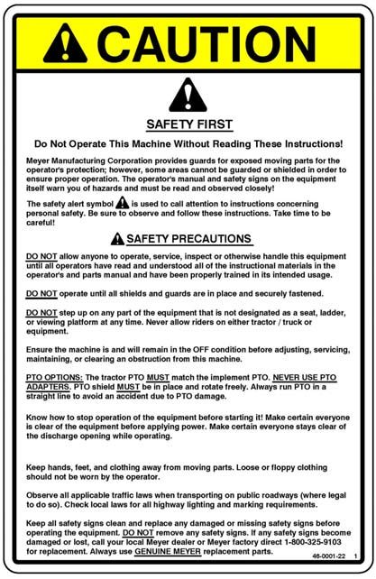
1.0 IMPORTANT INFORMATION

          The serial number plate is located on the front left hand side of the trailer above the manual holder.
Please enter the model, serial number and additional information in the space provided for future reference.

                                            Model No.

                                            Serial No.

                                    Date of Purchase

                                           Dealership

                               Dealership Phone No.
  Serial Number Plate

              Always use your serial number when requesting information or when ordering parts.

                                      HOW TO READ YOUR SERIAL NUMBER

                                                 EXAMPLE: 21F201

                                      Model Year / Model / Sequence Of Build

                                          21          F           201

                                           Meyer Manufacturing Corporation
                                             674 W. Business Cty Rd A
                                               Dorchester, WI 54425
                                              Phone: 1-800-325-9103
                                                 Fax: 715-654-5513
                                            Email: parts@meyermfg.com
                                            Website: www.meyermfg.com

Meyer Manufacturing Corporation                            -2-                                                 PB-FATBOY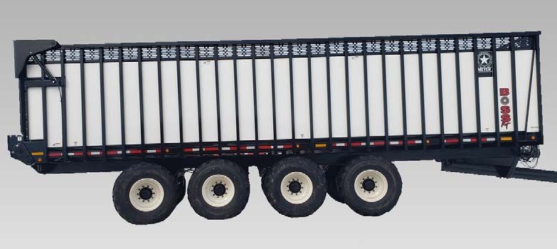
2.0 PRE-DELIVERY & DELIVERY CHECK LIST
                                                                                                            PB-FATBOY Check List
                                    Meyer Manufacturing Corporation
               Phone: 715-654-5132 • Toll-Free: 1-800-325-9103 • P.O. Box 405 • Dorchester, WI 54425

  This Pre-Delivery & Delivery Check List must be gone through by the Selling Party and the Customer to validate the
  Owner’s Registration Form.

   PRE-DELIVERY CHECK LIST                                          DELIVERY CHECK LIST

   After the New Meyer Forage Box has been completely               The following check list is an important reminder of
   set-up, check to be certain it is in correct running order       valuable information that MUST be passed on to the
   before delivering it to the customer.                            customer at the time the unit is delivered.

   The following is a list of points to inspect:                    Check off each item as you explain it to the
                                                                    customer.
   Check off each item as you have made the proper
   adjustments and found the item operating
                                                                         Explain to the customer that pre-delivery check
   satisfactorily. Any adjustments made, MUST be
                                                                         list was fully completed.
   according to specifications defined in this manual.
                                                                         Give customer the Owner & Operator’s Manual.
                                                                         Instruct to read and completely understand its
        All shields and guards are in place and securely                 contents BEFORE attempting to operate the
        fastened.                                                        Forage Box.

                                                                         Explain and review with customer the New Meyer
        All bolts and other fasteners are secure and tight.
                                                                         Forage Box manufacturer’s warranty.
        All mechanisms operate trouble free.                             Show the customer where to find the serial
                                                                         number on the implement.
        All grease fittings have been lubricated and gear
        boxes filled to proper levels. See “Lubrication”                 Explain and review with the customer “Safety
        section of this manual.                                          Precautions” section of this manual.

        Main Apron Chains are at proper tension. See                     Explain and review with customer the proper
        “Adjustments” section in this manual.                            “Start-up and Operating Procedures” sections of
                                                                         this manual.
        All decals are in place and legible.
                                                                         Demonstrate the start-up & shut-down controls,
        All stop/tail/turn lights work properly.                         proper hydraulic hose storage and tip holder
                                                                         used to keep system clean from contaminants.

                                                                         Explain that regular lubrication and proper
                                                                         adjustments are required for continued proper
                                                                         operation and long life of the Forage Box. Review
                                                                         with the customer the “Lubrication” and
                                                                         “Adjustments” sections of this manual.

                                                                         Explain the importance of apron chain tension,
                                                                         and the need to watch and tighten during the
                                                                         break in period.

                                                                         Fully complete this “PRE-DELIVERY                 &
                                                                         DELIVERY CHECK LIST” with the customer.

                                                                                                               1-800-325-9103
PB-FATBOY Check List                                          -3-                                          www.meyermfg.com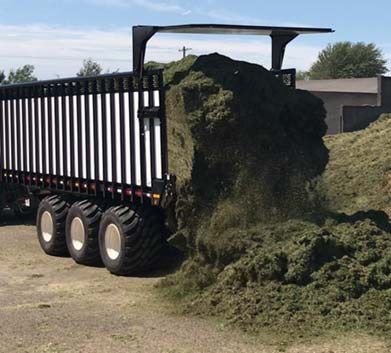
Meyer Manufacturing Corporation
                                        674 W. Business Cty Rd A
                                          Dorchester, WI 54425
                                         Phone: 1-800-325-9103
                                            Fax: 715-654-5513
                                       Email: parts@meyermfg.com
                                       Website: www.meyermfg.com

                      FARM EQUIPMENT BUYERS TRUST THE NAME MEYER!

Meyer Manufacturing Corporation                  -4-                PB-FATBOY Check List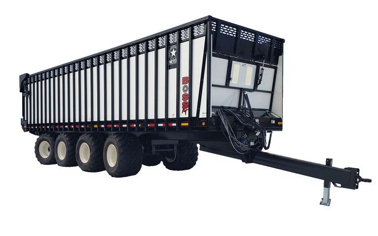
3.0 INTRODUCTION
Congratulations on your purchase of a new Meyer farm equipment product. Undoubtedly you have given
much consideration to your purchase and we’re proud that you have selected Meyer. Pride in craftsmanship,
engineering and customer service have made Meyer products the finest in the farm equipment industry today.

There is no substitute for quality. That is why thousands of people like you have purchased Meyer farm
equipment. They felt it was the best equipment to serve their farming needs, now and in years to come. We
ask that you follow our policy of “safety first”, and we strongly suggest that you read through the “Owner /
Operator’s Manual & Parts Book” before operating your Meyer farm equipment. Meyer Manufacturing
Corporation wants to thank you for not compromising quality. We are determined to offer excellence in
customer service as well as provide you with the very best value for your dollar.
Sincerely,
All Employees of
MEYER MANUFACTURING CORPORATION

The Fatboy RT is available as a pull type forage box and powered by a farm tractor.

The Fatboy RT may be referred to as 10 series, rear unload box, forage box, or rear unload forage box in this manual.

             IMPORTANT: You are urged to study this manual and follow the instructions carefully. Your efforts will be
             repaid in better operation and service as well as a savings in time and repair expense. Failure to read this
             manual and understand the machine could lead to serious injury. If you do not understand instructions in
             this manual, contact either your dealer or Meyer Manufacturing Corp. at Dorchester, WI 54425.

             WARRANTY: At the front of this manual is a an “Owner's Registration Form”. Be sure your dealer has
             completed this form and promptly forwarded a copy to Meyer Manufacturing to validate the manufacturer’s
             warranty. The product model and serial number are recorded on this form and on the inside of the front
             cover for proper identification of your Meyer Forage Box by your dealer and the manufacturer when
             ordering repair parts. The serial number plate is located on the front left hand side of the trailer above the
             manual holder.

             REPAIR PARTS: At the back of this manual is the repair parts section. All replacement parts are to be
             obtained from or ordered through your Meyer dealership. When ordering repair parts, refer to the parts
             section and give complete information including quantity, correct part number, detailed description and
             even model and serial numbers of the forage box which needs repair parts.

Manufacturer’s Statement: Meyer Manufacturing Corporation reserves the right to make improvements in design, or
changes in specifications at any time, without incurring any obligation to owners of units previously sold. This supersedes
all previous published instructions.

                                                                                                            1-800-325-9103
PB-FATBOY                                                   -5-                                         www.meyermfg.com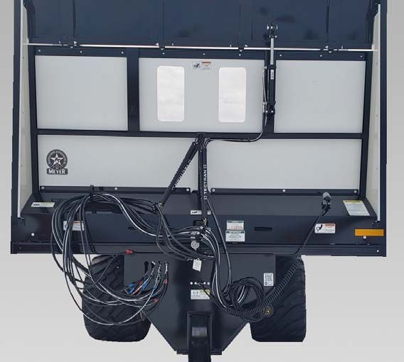
FEATURES

DESCRIPTION                                   1026RT RR/RS   1030RT SRS/RRS   1036RT SRRS
All Steel Welded frame                            STD             STD            STD
Clad-Tuff Fiberglass Woven                        STD             STD            STD
Side & Front Panels                               STD             STD            STD
Solid, High Molecular Poly Floor                  STD             STD            STD
Tire Size                                      710/50R26.5     800/45R26.5    800/45R26.5
Integrated Brakes - Hydraulic                     STD             STD            STD
Hydraulic Suspension W/ Ride Height Adj           STD             STD            STD
Dual Hydraulic Gear Drive                         STD             STD            STD
Hydraulic Hi-Lift Tailgate                        STD             STD            STD
29” Hydraulic Front Fold-Down                     STD             STD            STD
Articulating Ag Hitch / Bull Pull                 STD             STD            STD
Double Viewing Window                             STD             STD            STD
LED Rear Turn Signal Lights                       STD             STD            STD
LED Marker / Clearance Lights / DOT Tape          STD             STD            STD
Personalized Farm name on Sides                   STD             STD            STD
No Roof                                           STD             STD            STD

OPTIONS

DESCRIPTION                                   1026RT RR/RS   1030RT SRS/RRS   1036RT SRRS
Optional Tire Size                             800/45R26.5         NA             NA
Front Lift Axle                                   OPT*            OPT            OPT
Side-Mtd. LED Turn Signals in Addition to
                                                  OPT             OPT            OPT
Standard
Black Frame Paint                                 STD             STD            STD
Steel Fenders W/ Rear Flaps                       STD             STD            STD
Scales                                             NA              NA             NA
* No Front Lift Axle Available on 1026RT-RS

Meyer Manufacturing Corporation                   -6-                              PB-FATBOY
TABLE OF CONTENTS

1.0 IMPORTANT INFORMATION . . . . . . . . . . . . . . . . . . . . . . . . . . . . . . . . . . . . . . . . . . . . . . . . . . . 2
2.0 PRE-DELIVERY & DELIVERY CHECK LIST . . . . . . . . . . . . . . . . . . . . . . . . . . . . . . . . . . . . . . . 3
3.0 INTRODUCTION . . . . . . . . . . . . . . . . . . . . . . . . . . . . . . . . . . . . . . . . . . . . . . . . . . . . . . . . . . . . . 5
4.0 MANUFACTURER’S WARRANTY . . . . . . . . . . . . . . . . . . . . . . . . . . . . . . . . . . . . . . . . . . . . . . 9
5.0 SAFETY . . . . . . . . . . . . . . . . . . . . . . . . . . . . . . . . . . . . . . . . . . . . . . . . . . . . . . . . . . . . . . . . . . 11
       5.1 SAFETY PRECAUTIONS . . . . . . . . . . . . . . . . . . . . . . . . . . . . . . . . . . . . . . . . . . . . . . . . 12
           5.1.1 Farm Implement Tires . . . . . . . . . . . . . . . . . . . . . . . . . . . . . . . . . . . . . . . . . . . . . . . 13
       5.2 SAFETY SIGNS . . . . . . . . . . . . . . . . . . . . . . . . . . . . . . . . . . . . . . . . . . . . . . . . . . . . . . . . 14
       5.3 SHUTOFF & LOCKOUT POWER . . . . . . . . . . . . . . . . . . . . . . . . . . . . . . . . . . . . . . . . . . 18
           5.3.1 Shutoff & Lockout Power Recommendations . . . . . . . . . . . . . . . . . . . . . . . . . . . . . 18
6.0 PRE-OPERATION . . . . . . . . . . . . . . . . . . . . . . . . . . . . . . . . . . . . . . . . . . . . . . . . . . . . . . . . . . . 19
       6.1 STATIC INSPECTION . . . . . . . . . . . . . . . . . . . . . . . . . . . . . . . . . . . . . . . . . . . . . . . . . . . 19
       6.2 LIGHT HOOK-UP . . . . . . . . . . . . . . . . . . . . . . . . . . . . . . . . . . . . . . . . . . . . . . . . . . . . . . . 20
       6.3 HYDRAULIC HOOK-UP . . . . . . . . . . . . . . . . . . . . . . . . . . . . . . . . . . . . . . . . . . . . . . . . . . 20
       6.4 HITCHING TO TRACTOR . . . . . . . . . . . . . . . . . . . . . . . . . . . . . . . . . . . . . . . . . . . . . . . . 21
           6.4.1 Jack Storage . . . . . . . . . . . . . . . . . . . . . . . . . . . . . . . . . . . . . . . . . . . . . . . . . . . . . 21
       6.5 SET UP . . . . . . . . . . . . . . . . . . . . . . . . . . . . . . . . . . . . . . . . . . . . . . . . . . . . . . . . . . . . . . 22
       6.6 START-UP AND SHUT-DOWN . . . . . . . . . . . . . . . . . . . . . . . . . . . . . . . . . . . . . . . . . . . . 23
           6.6.1 Start-Up . . . . . . . . . . . . . . . . . . . . . . . . . . . . . . . . . . . . . . . . . . . . . . . . . . . . . . . . . 23
           6.6.2 Shut-Down . . . . . . . . . . . . . . . . . . . . . . . . . . . . . . . . . . . . . . . . . . . . . . . . . . . . . . 23
       6.7 OPERATIONAL CHECKS . . . . . . . . . . . . . . . . . . . . . . . . . . . . . . . . . . . . . . . . . . . . . . . . 24
           6.7.1 Controls . . . . . . . . . . . . . . . . . . . . . . . . . . . . . . . . . . . . . . . . . . . . . . . . . . . . . . . . . 24
       6.8 TRANSPORTING . . . . . . . . . . . . . . . . . . . . . . . . . . . . . . . . . . . . . . . . . . . . . . . . . . . . . . . 25
           6.8.1 Safety Chain . . . . . . . . . . . . . . . . . . . . . . . . . . . . . . . . . . . . . . . . . . . . . . . . . . . . . 26
           6.8.2 Brake Information . . . . . . . . . . . . . . . . . . . . . . . . . . . . . . . . . . . . . . . . . . . . . . . . . 27
           6.8.2.1 Lever Operated Hydraulic Brakes . . . . . . . . . . . . . . . . . . . . . . . . . . . . . . . . . . . 27
           6.8.2.2 Pedal Operated Hydraulic Brakes . . . . . . . . . . . . . . . . . . . . . . . . . . . . . . . . . . . 27
           6.8.3 Reverse Lock Instruction (Steering Axle Option Only) . . . . . . . . . . . . . . . . . . . . . 27
           6.8.4 Tractor Towing Size Requirements . . . . . . . . . . . . . . . . . . . . . . . . . . . . . . . . . . . . 28
7.0 OPERATION . . . . . . . . . . . . . . . . . . . . . . . . . . . . . . . . . . . . . . . . . . . . . . . . . . . . . . . . . . . . . . 29
       7.1 LOADING . . . . . . . . . . . . . . . . . . . . . . . . . . . . . . . . . . . . . . . . . . . . . . . . . . . . . . . . . . . . . 29
       7.2 UNLOADING . . . . . . . . . . . . . . . . . . . . . . . . . . . . . . . . . . . . . . . . . . . . . . . . . . . . . . . . . . 30
       7.3 UNHOOKING THE TRACTOR . . . . . . . . . . . . . . . . . . . . . . . . . . . . . . . . . . . . . . . . . . . . 31

                                                                                                                             1-800-325-9103
PB-FATBOY                                                             -7-                                                www.meyermfg.com
8.0 MAINTENANCE . . . . . . . . . . . . . . . . . . . . . . . . . . . . . . . . . . . . . . . . . . . . . . . . . . . . . . . . . . . . 33
       8.1 LUBRICATION . . . . . . . . . . . . . . . . . . . . . . . . . . . . . . . . . . . . . . . . . . . . . . . . . . . . . . . . . 33
       8.2 ADJUSTMENTS . . . . . . . . . . . . . . . . . . . . . . . . . . . . . . . . . . . . . . . . . . . . . . . . . . . . . . . . 35
       8.3 SUSPENSION TORQUE REQUIREMENTS . . . . . . . . . . . . . . . . . . . . . . . . . . . . . . . . . . 36
       8.4 WHEEL TORQUE REQUIREMENTS . . . . . . . . . . . . . . . . . . . . . . . . . . . . . . . . . . . . . . . 36
       8.5 FARM IMPLEMENT TIRES . . . . . . . . . . . . . . . . . . . . . . . . . . . . . . . . . . . . . . . . . . . . . . . 36
           8.5.1 Tire Inflation . . . . . . . . . . . . . . . . . . . . . . . . . . . . . . . . . . . . . . . . . . . . . . . . . . . . . 37
       8.6 BRAKES . . . . . . . . . . . . . . . . . . . . . . . . . . . . . . . . . . . . . . . . . . . . . . . . . . . . . . . . . . . . . . 37
       8.7 STORING THE FORAGE BOX . . . . . . . . . . . . . . . . . . . . . . . . . . . . . . . . . . . . . . . . . . . . 38
       8.8 RETURNING THE FORAGE BOX TO SERVICE . . . . . . . . . . . . . . . . . . . . . . . . . . . . . . 38
9.0 SPECIFICATIONS . . . . . . . . . . . . . . . . . . . . . . . . . . . . . . . . . . . . . . . . . . . . . . . . . . . . . . . . . . 39
MAINTENANCE RECORD . . . . . . . . . . . . . . . . . . . . . . . . . . . . . . . . . . . . . . . . . . . . . . . . . . . . . . . . 4 3

Meyer Manufacturing Corporation                                      -8-                                                         PB-FATBOY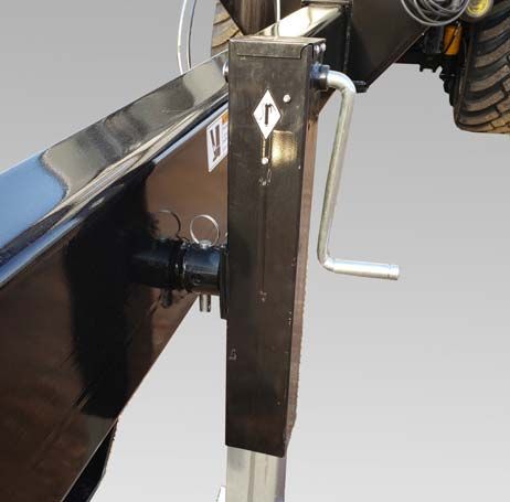
4.0 MANUFACTURER’S WARRANTY

                                                                                                                              01/2021
                               MEYER “FATBOY RT” FORAGE BOX
   I.       The “Owner's Registration Form” must be completed in full and promptly returned to Meyer Mfg. Corp. for this
            warranty to become both valid and effective. All warranties on new Meyer forage boxes shall apply only to the
            original retail customer from an authorized Meyer Mfg. Corp. dealership.
   II.      This warranty shall not apply to any Meyer forage box which has been subjected to misuse, negligence, alteration,
            accident, incorrect operating procedures, has been used for an application not designed for or pre-authorized by
            Meyer in writing, has had the serial numbers altered, or which shall have been repaired with parts other than those
            obtained through Meyer Mfg. Corp. Meyer is not responsible for the following: Depreciation or damage caused by
            normal wear, lack of reasonable and proper maintenance, failure to follow the operator’s manual recommendations
            or normal maintenance parts and service. Meyer is not responsible for rental of replacement equipment during
            warranty repairs, damage to a power unit (including but not limited to a truck or tractor), loss of earnings due to
            equipment down time, or damage to equipment while in transit to or from the factory or dealer.
   III.     Meyer Mfg. Corp. warrants new Meyer forage box to be free from defects in material and workmanship under
            recommended use and maintenance service, as stated in the “Owner / Operator’s Manual and Parts Book”, as
            follows:
                A.       Meyer Mfg. Corp. will repair or replace F.O.B. Dorchester, WI, as Meyer Mfg. Corp. elects, any part of
                         a new Meyer forage box which is defective in material or workmanship:
                                 i.     Without charge for either parts or labor during the first (1) year from purchase date to the
                                        original retail customer.
                                 ii.    Without charge for parts only during the second (2) year from purchase date to the original
                                        retail customer.

                B.       In addition to the above basic warranty, Meyer Mfg. Corp. will repair or replace F.O.B. Dorchester, WI
                         as Meyer Mfg. Corp. elects:
                                 i.     Any part of the following which is defective in material or workmanship (not neglect to
                                        recommended use and service) without charge for parts only (not labor) during the stated
                                        time periods from date of purchase to the original retail customer:
                Two (2) Years:         a. The DH667XH pintle main apron chain assembly.

                                 ii.    Any part of the following which is defective in material or workmanship (not neglect to
                                        recommended use and service) with a “pro-rated” charge for parts only (not labor) during the
                                        stated time period from date of purchase to the original retail customer:
               Ten (10) Years:          a. The all welded steel frame box structure.

   IV.      Repairs eligible for labor warranty must be made by Meyer Mfg. Corp. or an authorized Meyer dealership. The original
            retail customer is responsible for the transportation of the forage box to the dealership for warranty service or for any
            service call expenses.
   V.       Except as stated above, Meyer Mfg. Corp. shall not be liable for injuries or damages of any kind or nature, direct,
            consequential, or contingent, to persons or property. This warranty does not extend to loss of crop or for any other
            reasons.
   VI.      No person is authorized to give any warranties or to assume any other obligation on Meyer Mfg. Corp.’s behalf unless
            made or assumed in writing by Meyer Mfg. Corp. This warranty is the sole and exclusive warranty which is applicable
            in connection with the manufacture and sale of this product and Meyer Mfg. Corp's responsibility is limited
            accordingly.

   VII.     Tires, optional scales and tarps fall under the original manufacturer’s warranty.

                                                                                                                       1-800-325-9103
PB-FATBOY                                                          -9-                                             www.meyermfg.com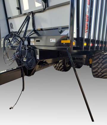
Meyer Manufacturing Corporation - 10 - PB-FATBOY
5.0 SAFETY

The Meyer Forage Box is manufactured with operator safety in mind. Located on the forage box are various safety signs
to aid in operation and warn of hazardous areas. Pay close attention to all safety signs on the forage box.
Carefully follow the operating and maintenance instructions in this manual and all applicable safety laws. Failure to follow
all safety procedures may result in serious injury or death.
Before attempting to operate this forage box, read and study the following safety information. In addition, make
sure that every individual who operates or works with the forage box, whether family member or employee, is
familiar with these safety precautions.

Meyer Mfg. Corp. provides guards for exposed moving parts for the operator’s protection; however, some areas
cannot be guarded or shielded in order to assure proper operation. The operator’s manual and safety signs on
the forage box itself warn you of hazards and must be read and observed closely!

                                                             This symbol is used to call attention to instructions
                                                             concerning personal safety. Be sure to observe and
                                                             follow these instructions. Take time to be careful!

                                             The signal word DANGER on the machine and in the manual identifies
                                             a hazardous situation which, if not avoided, WILL result in death or
                                             serious injury.

                                             The signal word WARNING on the machine and in the manual
                                             indicates a potentially hazardous situation which, if not avoided,
                                             COULD result in death or serious injury.

                                             The signal word CAUTION on the machine and in the manual indicates
                                             a potentially hazardous situation which, if not avoided, MAY result in
                                             minor or moderate injury. It may also be used to alert against unsafe
                                             practices.

                                             This notice identifies procedures which must be followed to avoid
                                             damage to the machine.

Danger, Warning, Caution, and instructional decals and plates are placed on the equipment to protect anyone working on
or around this machine, as well as the components of the machine. All personnel operating or maintaining this equipment
must familiarize themselves with all Danger, Warning, Caution, and instructional decals and plates.

                                                                                                           1-800-325-9103
PB-FATBOY                                                  - 11 -                                      www.meyermfg.com
5.1 SAFETY PRECAUTIONS
All individuals who will operate this Forage Box must read
and completely understand this Operator’s And Parts
Manual. Operator must have instructions before operating
the machine. Untrained operators can cause injury or death.
• The PB-ADR-B manual should be used in conjunction with this manual.
• DO NOT allow anyone to operate, service, inspect or otherwise handle this forage box until all operators have read
and understood all of the instructional materials in this Operator’s And Parts Manual and have been properly trained
in its intended usage.
• For an operator to be qualified, he or she must not use drugs or alcohol which impair alertness or coordination while
working. An operator who is taking prescription drugs must get medical advice to determine if he or she can safely
operate a machine and the equipment.
• Make sure all personnel can READ and UNDERSTAND all safety signs.
• DO NOT allow minors (children) or inexperienced persons to operate this forage box.
• DO NOT operate until all shields and guards are in place and securely fastened.
• DO NOT step up on any part of the forage box at any time.
• DO NOT adjust, clean or lubricate while the forage box is in motion.
• Inspect when first delivered and regularly thereafter; that all connections and bolts are tight and secure before
operating.
• Know how to stop operation of the forage box before starting it!
• Make certain everyone is clear of the forage box before applying power.
• Keep hands, feet and clothing away from moving parts. Loose or floppy clothing should not be worn by the operator.
• Observe all applicable traffic laws when transporting on public roadways (where legal to do so). Check local laws for
all highway lighting and marking requirements.
• Shut off and lock out power before adjusting, servicing, maintaining or clearing an obstruction from this machine. (See
5.3 SHUTOFF & LOCKOUT POWER on page 18.)
• Always enter curves or drive up or down hills at a low speed and at a gradual steering angle.
• Never allow riders on either tractor or equipment.
• Keep tractor in a lower gear at all times when traveling down steep grades.
• Maintain proper brake settings at all times (if equipped).
• Stay away from overhead power lines. Electrocution can occur without direct contact.
• Use only properly rated undercarriage and tires.
Meyer Manufacturing Corporation - 12 - PB-FATBOYSafety Precautions For Tractor Towed Units:
• Do not exceed 20 mph (32 kph). Reduce speed on rough roads and surfaces.
• Always install a SMV emblem on pull-type equipment when transporting on roadways and keep clean and bright.
• Always yield to oncoming traffic in all situations and move to the side of the road so any following traffic may pass.
• Comply with state and local laws governing highway safety and movement of machinery on roadways.
Safety Precautions For Hydraulic System:
• Check hydraulic tubes, hoses and fittings for damage and leakage. Never use hands to check for leaks. Hydraulic
tubes and hoses must be properly routed and have adequate support and secure clamps. Tighten or replace any parts
that show leakage.
• Always clean fluid spills. Do not use gasoline or diesel fuel for cleaning parts. Use commercial nonflammable solvents.
5.1.1 Farm Implement Tires
Recommended Safety Precautions
• Always remove the valve core and deflate the tire before any work is performed.
• Always use the proper and approved tools to demount and mount the tire.
• Always inspect all rim/wheel parts for wear, damage, cracks, rust or mismatched components.
• Always destroy damaged or unserviceable parts.
• Always inspect the tube and tire for cord or side damage, cuts or wear. Unrepairable damaged items must be
discarded.
• Always check for mismatched components or tire and wheel sizes.
• Always lubricate tire with a non-flammable tire lubricant approved for that purpose.
• Always place tire and wheel in inflation cage or restraining device before inflating beyond 5 PSI.
• Always use an extension hose with a PSI gauge and clip on chuck when inflating the tire so you can stand to one side.
Non - Recommended Safety Precautions
• Never work on a tire / wheel assembly before removing the valve core and completely deflating.
• Never re-inflate a tire that has been run flat or in an under inflated condition before removing and inspection.
• Never reuse damaged, defective, worn or mismatched parts.
• Never rework, weld, heat or braze any rim / wheel parts for any reason.
• Never inflate any tire beyond 40 PSI to seat the beads. If beads are not seated at 40 PSI. STOP! Deflate and determine
problem.
• Never hammer, strike or pry on a rim / wheel assembly that contains any inflation pressure.
• Never inflate a tire without using an inflation cage or restraining device.
• Never inflate beyond the maximum PSI specified for the tire or rim.
1-800-325-9103
PB-FATBOY - 13 - www.meyermfg.com5.2 SAFETY SIGNS
Read all safety signs on the Forage Box and in this manual. Keep all
safety signs clean and replace any damaged or missing safety signs
before operating the equipment. Do Not remove any safety signs.
Safety signs are for operator protection and information.
FRONT OF FORAGE BOX
1
1
2 PART NO. 46-9100-4
CAUTION
TO PREVENT SERIOUS INJURY OR DEATH
• DO NOT start, operate, or work on this machine without first carefully reading and
thoroughly understanding the entire contents of the operators manual. (Require the
same of all personnel who will operate this machine.)
• If operators manual is lost, contact your nearest Meyer Dealership or write or call:
MEYER MFG., CORP.
P.O. BOX 405 • Dorchester, WI 54425-0405
Phone 1-800-325-9103
2 Please give your name, address, phone number, model and serial number of your
machine. A manual will be furnished.
6 • If you have any questions about operation or adjustments, and maintenance of this
machine, contact your Meyer Dealership or Meyer Mfg., Corp. before starting or
3 3 46-0001-35 1
continuing the operation of this machine.
4 PART NO. 46-0001-35
5
3
WARNING
6
ENTANGLEMENT
HAZARD
KEEP ALL SHIELDS IN
PLACE WHILE MACHINE
IS RUNNING
46-0001-4 1
PART NO. 46-0001-4
4
PART NO. 46-8500-7
5
PART NO. 46-0001-22 PART NO. 46-0001-62
Meyer Manufacturing Corporation - 14 - PB-FATBOYREAR OF FORAGE BOX
1
2
1
PART NO. 46-0011-D
2
WARNING
ENTANGLEMENT
HAZARD
KEEP ALL SHIELDS IN
PLACE WHILE MACHINE
IS RUNNING
46-0001-4 1
PART NO. 46-0001-4
LEFT SIDE OF FORAGE BOX
3 3
4 4 5 4
4
3 4
PART NO. 46-9100-4
5
PART NO. 46-0001-205
PART NO. 46-8500-7
1-800-325-9103
PB-FATBOY - 15 - www.meyermfg.comRIGHT SIDE OF FORAGE BOX
1 1
2
2 3 2
2
1 2
PART NO. 46-9100-4
3
PART NO. 46-0001-205
PART NO. 46-8500-7
Meyer Manufacturing Corporation - 16 - PB-FATBOYHITCH OF FORAGE BOX
4
1 2 3 4
1
PART NO. 46-3600-6 PART NO. 46-0800-8
2 3
PART NO. 46-0800-6 PART NO. 46-0800-7
1-800-325-9103
PB-FATBOY - 17 - www.meyermfg.com5.3 SHUTOFF & LOCKOUT POWER
Any individual that will be adjusting, servicing, maintaining, or clearing an obstruction from this machine needs
to ensure that this machine stays safely “OFF” until the adjustment, service, or maintenance has been
completed, or when the obstruction has been cleared, and that all guards, shields, and covers have been
restored to their original position. The safety of all individuals working on or around this machine, including
family members, are affected. The following procedure will be referred to throughout this manual, so be familiar
with the following steps.
5.3.1 Shutoff & Lockout Power Recommendations
1. Think, Plan and Check
a. Think through the entire procedure and identify all the steps that are required.
b. Plan what personnel will be involved, what needs to be shut down, what guards / shields need to be removed, and
how the equipment will be restarted.
c. Check the machine over to verify all power sources and stored energy have been identified including engines,
hydraulic and pneumatic systems, springs and accumulators, and suspended loads.
2. Communicate - Let everyone involved, including those working on or around this machine, that work is being done
which involves keeping this machine safely “OFF”.
3. Power Sources
a. LOCKOUT - Shut off engines and take the key, or physically lock the start/on switch or control. Disconnect any
power sources which are meant to be disconnected (i.e. electrical, hydraulic, and PTO of pull-type units).
b. TAGOUT - Place a tag on the machine noting the reason for the power source being tagged out and what work is
being done. This is particularly important if the power source is not within your sight and/or will need to be isolated
for a longer period of time.
4. Stored Energy - Neutralize all stored energy from its power source. Ensure that this machine is level, set the parking
brake, and chock the wheels. Disconnect electricity, block moveable parts, release or block spring energy, release
pressure from hydraulic and pneumatic lines, and lower suspended parts to a resting position.
5. Test - Do a complete test and personally double check all of the above steps to verify that all of the power sources are
actually disconnected and locked out.
6. Restore Power - When the work has been completed, follow the same basic procedures, ensuring that all individuals
working on or around this machine are safely clear of the machine before locks and tags are removed and power is
restored.
It is important that everyone who works on this equipment is properly
trained to help ensure that they are familiar with this procedure and
that they follow the steps outlined above. This manual will remind you
when to Shutoff & Lockout Power.
Meyer Manufacturing Corporation - 18 - PB-FATBOY6.0 PRE-OPERATION
DO NOT allow anyone to operate, service, inspect or otherwise
handle this forage box until all operators have read and understand
all of the instructional materials in this Operator’s And Parts Manual
and have been properly trained in its intended usage.
Verify that the forage box is securely fastened to the tractor.
Verify that all electrical / hydraulic connections and bolts / hardware
are tight and securely fastened before operating the forage box.
Always keep all shields and guards in place and securely fastened.
Keep hands, feet and clothing away.
Wear safety glasses to prevent eye injury when any of the following
conditions exist:
• When fluids are under pressure.
• Flying debris or loose material is present.
• Tools are being used.
6.1 STATIC INSPECTION
Hydraulic fluid escaping under pressure can have sufficient force to
cause injury. Keep all hoses and connections in good serviceable
condition. Failure to heed may result in serious personal injury or
death.
Before operating the forage box for the first time and each time thereafter, check the following items:
1. Check that all safety signs are in good and legible condition.
2. Inspect the forage box for proper adjustments. (See 8.2 ADJUSTMENTS)
3. Lubricate the equipment. (See 8.1 LUBRICATION)
4. Make sure that all guards and shields are in place, secured and functioning as designed.
5. Check condition of all hydraulic components for leaks. Repair or replace as required.
6. Check the gear box oil level. (See 8.1 LUBRICATION)
7. Inspect the condition of safety lighting. Repair or replace as required.
8. Check to see that no obstructions are present in the forage box. Be sure that there are no tools laying on or in the
forage box.
9. Verify that all electrical and hydraulic connections are tight and secure before operating.
10. Check that all hardware is in place and is tight.
11. Watch for any worn or cracked welds. If found, have qualified personnel repair immediately or replacement is
necessary.
12. Check all bearings for wear. Replace as needed.
13. Check tires for proper inflation.
14. Check that the brakes are clean and clean them if necessary.
1-800-325-9103
PB-FATBOY - 19 - www.meyermfg.com6.2 LIGHT HOOK-UP
A 7 pin Ag electrical cord is provided to connect the 4 pin electrical control socket to your tractor. This will operate signal,
tail, clearance and brake lights.
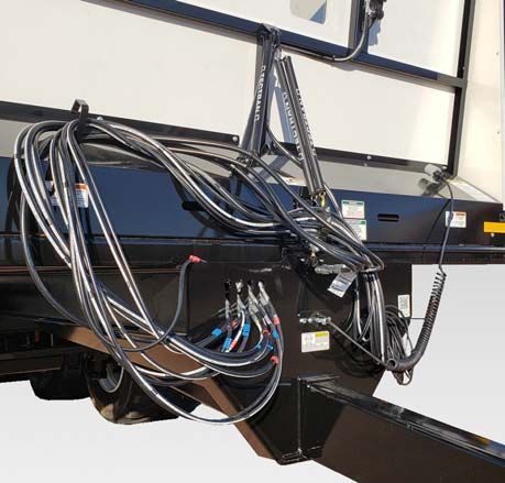
6.3 HYDRAULIC HOOK-UP
Requires 40 GPM @ 3000 PSI.
Hose Identification Colors & Quantities
Pressure: Red Cable Tie
Return: Blue Cable Tie
(1) Red (1) Blue Rear Unload
(2) Red (2) Blue Rear Unload
(3) Red (3) Blue Gate Extension
(4) Red (4) Blue Axle Lock-Unlock
(5) Red (5) Blue Hydraulic Suspension
(6) Red (6) Blue Hydraulic Brakes
NOTE: With tractors that have limited SCVs: The Axle Lock-Unlock (Optional) can be left disconnected if backing
up isn't required. The Hydraulic Suspension can be disconnected once section 6.5 Set Up is completed
and not intending to use the front lift axle (Optional). The box will run with one set of rear unload lines
connected but will hinder unloading performance substantially.
Tractor PTO Horsepower Requirements: The hydraulic horsepower requirements may not reflect adequate tractor size
for towing the machine. Refer to tractor weight requirements for these recommendations and safety section for additional
tractor and towing requirements.
Call the factory for further information.
Do not exceed maximum PSI or a motor failure could result.
Meyer Manufacturing Corporation - 20 - PB-FATBOY6.4 HITCHING TO TRACTOR
Move to the operator’s position, start the engine and release the parking brake.
Do not allow anyone to stand between the tongue or hitch and the
tractor when backing up to the Forage Box.
Move the tractor in front of the forage box. Slowly move the tractor backwards towards the forage box and align the
drawbar with the implement’s hitch.
NOTE: Lower or raise the forage box jack to properly align the drawbar and hitch.
Fasten the forage box hitch to the tractor drawbar with a properly sized hitch pin with safety retainer. (Reference ANSI/
ASABE AD6489-3 Agricultural vehicles - Mechanical connections between towed and towing vehicles - Part 3: Tractor
drawbar.)
Before operation and after hitching the tractor to the implement, connect the hydraulic hoses and light cord to the tractor.
6.4.1 Jack Storage
Keep hands, legs and feet from under tongue and hitch until jack is
locked into place.
After hitching the forage box to the tractor.
Using the handle, raise the jack off the ground and remove the pin.
Move the jack to the storage mount (Item 1) under the left hand
side of the forage box. Reinstall the pin to lock the jack into the
transport position.
NOTE: Keeping jack stored in proper position will keep it from
getting damaged during transportation.
1
1-800-325-9103
PB-FATBOY - 21 - www.meyermfg.com6.5 SET UP
Shutoff and lockout power before performing machine service,
adjusting, maintaining, or clearing an obstruction from this machine.
Refer to section 5.3 SHUTOFF & LOCKOUT POWER.
DO NOT allow anyone to operate, service, inspect or otherwise handle
this forage box until all operators have read and understand all of the
instructional materials in this Operator’s And Parts Manual and have
been properly trained in its intended usage.
Before operating the forage box, look in all directions and make sure
no bystanders, especially small children are in the work area.
Once the forage box is ready to be set up, follow the steps listed below:
1. Position forage box on level ground/surface.
2. Unfold the suspension height indicator (Item 1).
3. Turn the control box selector knob to LEVELING (Item 2).
4. Lift the forage box suspension using the tractors hydraulics.
5. Stop lifting the forage box once the suspension height indicator (Item 3) is allowed to become vertical.
6. Turn the control box selector knob to RUN (Item 4).
7. Fold the suspension height indicator into its storage location.
4
2
1
3
Meyer Manufacturing Corporation - 22 - PB-FATBOY6.6 START-UP AND SHUT-DOWN
DO NOT allow anyone to operate, service, inspect or otherwise handle
this forage box until all operators have read and understand all of the
instructional materials in this Operator’s And Parts Manual and have
been properly trained in its intended usage.
Before operating the forage box, look in all directions and make sure
no bystanders, especially small children are in the work area.
Disengage the hydraulic power, engage the machine’s parking brake,
stop the engine and make sure all moving components are
completely stopped before connecting, disconnecting, adjusting or
cleaning this equipment.
Always keep all shields and guards in place and securely fastened.
Keep hands, feet and clothing away.
6.6.1 Start-Up
Enter the tractor and start the engine.
Open the rear gate.
Slowly engage both rear unload SCVs and operate at idle speed.
6.6.2 Shut-Down
Disengage the hydraulics.
Lower the rear gate.
Park the tractor on a flat, level surface.
Engage the parking brake, stop the engine and exit the tractor.
1-800-325-9103
PB-FATBOY - 23 - www.meyermfg.com6.7 OPERATIONAL CHECKS
Shutoff and lockout power before performing machine service,
adjusting, maintaining, or clearing an obstruction from this machine.
Refer to section 5.3 SHUTOFF & LOCKOUT POWER.
DO NOT allow anyone to operate, service, inspect or otherwise handle
this forage box until all operators have read and understand all of the
instructional materials in this Operator’s And Parts Manual and have
been properly trained in its intended usage.
Before operating the forage box, look in all directions and make sure
no bystanders, especially small children are in the work area.
Always keep all shields and guards in place and securely fastened.
Keep hands, feet and clothing away.
Make certain all personnel are clear of the forage box before applying
power. Failure to heed may result in serious personal injury or death.
Before running material through the forage box for the first time and each time thereafter, follow the steps listed below.
1. Make sure forage box is empty.
2. Follow the Start-Up procedure section 6.6.1 Start-Up.
3. Operate the forage box for approximately 5-10 minutes.
4. Verify everything is working correctly.
5. Follow the Shut-Down procedure section 6.6.2 Shut-Down.
6. Check drive components to be sure components are not abnormally hot.
7. Check all hydraulic components for leaks.
8. Adjust and lubricate equipment as needed. (See 8.1 LUBRICATION) & (See 8.2 ADJUSTMENTS).
6.7.1 Controls
A control box is supplied with each forage box. There are 3 functions,
one to allow the tractor hydraulics to lift or lower the front axle (Key 1)
2
(optional), one to allow the suspension to self level (Key 2), one to allow
the tractor hydraulics to lift or lower the entire forage box (Key 3).
1 3
Meyer Manufacturing Corporation - 24 - PB-FATBOY6.8 TRANSPORTING
AVOID SERIOUS INJURY OR DEATH
• Read and understand owner’s manual before using. Review
safety precautions annually.
• Before operating the forage box, look in all directions and make
sure no bystanders, especially small children are in the work
area.
• No riders allowed when transporting.
• Do not drink and drive.
• Before moving, be sure required lights and reflectors are
installed and working.
• Before maintenance or repair, stop vehicle, set parking brake,
and remove ignition key.
• Place safety stands under frame and chock wheels before
working on tires or chassis.
• Maintain wheel bolts at torque as recommended in the manual.
• If equipped with brakes, maintain proper adjustment.
Pull-Type Units
• Use flashing warning lights when transporting on ALL highways
(public roadways) at ALL times (Tractor towed models) EXCEPT
WHEN PROHIBITED BY LAW! (Check w/local law enforcement).
• By all state and federal laws, implement lights do not replace the
SMV (Slow-Moving Vehicle) identification emblem. All towed
agricultural vehicles must display SMV emblems when traveling
LESS than 20 mph (32 kph).
• Check for traffic constantly. Be sure you can see that no one is
attempting to pass you and that all traffic is sufficiently clear
from you before making any turns.
• Securely attach to towing unit. Use a high strength appropriately
sized hitch pin with mechanical retainer and attach safety chain.
• Do not exceed 20 mph (32 kph). Slow down for corners and
rough terrain.
To Prevent Serious Injury Or Death
• Keeps hands and body out of the hitch area when attaching
towing vehicle.
• Keep body clear of crush point between towing vehicle and load.
To Prevent Serious Injury Or Death
• Shift to lower gear before going down steep grades.
• Avoid traveling on slopes or hills that are unsafe.
• Keep towing vehicle in gear at all times.
• Never exceed a safe travel speed (which may be less than 20
MPH.).
1-800-325-9103
PB-FATBOY - 25 - www.meyermfg.comYou must observe all applicable traffic laws when transporting on
public roadways. Check local laws for all highway lighting and
marking requirements. Failure to heed may result in serious
personal injury or death.
(Tractor Powered) Do not tow at speeds in excess of 20 mph. Failure
to heed may result in serious personal injury or death.
Forage box is to be used for agriculture use only. Travel only at
tractor speeds.
The PB-ADR-B manual should be used in conjunction with this
manual.
If you will travel on public roads and it is legal to do so, you must
know all rules governing such operation. This will include lighting
and brake requirements in addition to traffic rules.
NOTE: An Optional Highway Lighting Package is available to assist in meeting these requirements. See your
Meyer Dealer for Details.
6.8.1 Safety Chain
A safety chain must be installed to retain the connection between
the tractor (or other towing vehicle) and implement whenever
traveling on public roads in case the hitch connection would
separate.
The chain must be of adequate size to hold the weight of the loaded
forage box.
2
NOTE: If using a grab hook at the end(s) of the chain to secure
the chain to itself, a hook latch (Item 1) must be
installed.
The length of the safety chain is not to be any longer than
necessary to turn without interference. If any chain links or
attachment hardware are broken or stretched, repair before using.
Store chain so it does not corrode or become damaged. Do not use 1
this chain for other implements because the strength and length of
the chain may not be adequate. Identify this chain for use on this
particular forage box.
NOTE: Do not use the intermediate support (Item 2) as the attaching point.
If you do not have a safety chain, or a replacement safety chain is
needed, see your local Meyer dealer and do not operate on public
roads until you are able to travel with the safety chain properly
installed.
Meyer Manufacturing Corporation - 26 - PB-FATBOY6.8.2 Brake Information
Two optional brake systems are offered for your forage box. A brake system is recommended for any forage box operated
on public roads and may be a requirement.
6.8.2.1 Lever Operated Hydraulic Brakes
This brake system is connected to the tractor remote hydraulic ports and is controlled by the tractor hydraulic system. The
two hose system has a hydraulic manifold with pressure relief to prevent the pressure to the brake activating cylinders to
exceed the relief valve setting.
Applying hydraulic pressure from the tractor causes tractor hydraulic fluid to flow under pressure to the pressure relief
valve and activates the brake activating cylinders to apply the brakes.
Applying The Brakes - Gradually move the tractor spool valve lever as required to apply the brake. The hydraulic
hoses should be connected to the tractor ports so the spool valve lever gives the expected response. Test this after
hooking up. If response is opposite of expected, reverse the hoses.
Releasing The Brakes - Move the tractor spool valve lever to the opposite direction and hold momentarily. Then
return lever to the “float” position.
NOTE: Simply returning the spool valve lever to the neutral position without first moving the lever to the opposite
position will not release the brakes.
When brakes are not required, the spool valve lever must be in the
“float” position on the tractor spool valve.
6.8.2.2 Pedal Operated Hydraulic Brakes
This brake system is a one hose system. The single hydraulic hose must be connected to the tractor remote pedal port.
Applying The Brakes - Gradually apply the tractor brake pedal to apply the brakes.
Releasing The Brakes - Release the tractor brake pedal to release the brakes.
At no time should the brake system be used as a parking brake. With
loss of hydraulic pressure, the brakes will lose their holding power.
6.8.3 Reverse Lock Instruction (Steering Axle Option Only)
Connect the hydraulic hoses to a bank on your tractor. Apply pressure to extend the cylinders. This will lock the steering
axles in a straight position to allow you to back up. When you are done backing up, return the cylinders to their retracted
position.
1-800-325-9103
PB-FATBOY - 27 - www.meyermfg.com6.8.4 Tractor Towing Size Requirements
Use the following charts to help calculate the minimum tractor weight when towing without implement brakes. The
minimum tractor weight, up to 20 mph (33 kph) needs to be 2/3’s of the box Gross Weight (GW). Gross Weight is
calculated by the empty weight of the box and undercarriage combined added to the Load Weight. Then take the Gross
Weight and multiply it by 0.667 and you will get the Minimum Required Weight of the Tractor.
Gross Weight
FORAGE BOX UNDERCARRAIGE LOAD (LBS) GROSS WEIGHT (GW)
WEIGHT, EMPTY WEIGHT (LBS) (LBS)
(LBS)
+ + = GW
+ + =
Minimum Required Weight of the Tractor
2/3 GROSS MINIMUM TRACTOR
WEIGHT WEIGHT (LBS)
(GW) (LBS)
0.667 x GW = TW
x =
Meyer Manufacturing Corporation - 28 - PB-FATBOY7.0 OPERATION
DO NOT allow anyone to operate, service, inspect or otherwise
handle this forage box until all operators have read and understand
all of the instructional materials in this Operator’s And Parts Manual
and have been properly trained in its intended usage.
Before operating the forage box, look in all directions and make sure
no bystanders, especially small children are in the work area.
Do not climb or step on any part of the forage box at any time.
Turn on level ground. Slow down when turning.
Go up and down slopes, not across them.
Keep the heavy end of the machine uphill.
Do not overload the machine.
Check for adequate traction.
7.1 LOADING
Shutoff and lockout power before performing machine service,
adjusting, maintaining, or clearing an obstruction from this machine.
Refer to section 5.3 SHUTOFF & LOCKOUT POWER.
Overloading may cause failure of axles, tires, structural members,
hitches, loss of vehicle control. DO NOT exceed maximum gross
weight. (See 9.0 SPECIFICATIONS on page 39.)
Filling the forage box evenly from the front to rear will ensure there is
downward force on the tractor hitch and provide traction for the
tractor wheels.
NOTE: If equipped, make sure the front lift axle is in the lowered position before loading the forage box.
NOTE: Heaping material over the sides of the box will add a significant amount of weight to the load.
NOTE: Overloading can have detrimental effects on the integrity of the implement and it’s safe use. Some
materials such as soybeans may not be able to be filled to struck level. Overloading will void warranty and
increase risk to the operator's safety. Always be aware of your gross weight.
MAXIMUM FORAGE BOX GROSS WEIGHT MATERIAL ESTIMATED WEIGHT
PER CUBIC FOOT
MODEL LBS MATERIAL LBS / CU.FT.
1026RT Soybeans 47 lbs.
1030RT Cotton Seed (Dry) 20 lbs.
1036RT Corn (Shelled) 45 lbs.
Corn Silage 30 lbs.
Haylage 20 lbs.
Sawdust 17 lbs.
NOTE: Maximum Gross Weight is the lesser value between the Implement, chassis, or tires.
NOTE: The front of the forage box is equipped with a plexiglass window(s) to monitor forage level from the
operator’s position.
1-800-325-9103
PB-FATBOY - 29 - www.meyermfg.comDrive alongside the loading vehicle. Fill the forage box evenly to properly distribute the load while loading. When dumping
into the box with an end-loader, center the bucket just forward of the axle to properly distribute the load while loading.
NOTE: The suspension can be lowered in order to allow equipment to load the forage box. Once the forage box
is loaded, follow section 6.5 SET UP to allow the forage box suspension to operate at the center of travel.
7.2 UNLOADING
Shutoff and lockout power before performing machine service,
adjusting, maintaining, or clearing an obstruction from this machine.
Refer to section 5.3 SHUTOFF & LOCKOUT POWER.
STAND CLEAR, the rear discharge door can open quickly and with
extreme force.
Keep all persons well clear of the rear discharge door, forage box and
unloading area.
The unloading process described is to be performed by the operator
alone. This will eliminate unexpected “start-ups” and minimize other
hazards that could result by more than one person in control.
NOTE: Unloading is best observed from the operator’s seat.
NOTE: The front of the forage box is equipped with plexiglass windows to monitor forage level from the
operator’s seat.
NOTE: If equipped with steer axles, follow section 6.8.3 Reverse Lock Instruction (Steering Axle Option Only)
when backing up.
Enter the tractor, start the engine, release the parking brake.
Move the tractor and forage box to the unloading area.
Place all tractor controls in neutral, engage the parking brake and SLOWLY
engage the apron chains to open the rear door.
Once the load has started to move, release the parking brake, move forward
to prevent the silage from being carried underneath into the main apron
chain return area. The front of the box has a plexiglass window for
convenient observation.
When finished unloading, reduce engine speed to idle and disengage the
hydraulics. Move the forage box forward, away from the unloaded pile of Unloading The Forage Box
forage. Close the rear door when you have cleared enough distance to not
impede the door. Unloading The Forage Box
Use the plexiglass windows to verify the door is in the closed position.
Meyer Manufacturing Corporation - 30 - PB-FATBOYNever enter the forage box without shutting power “OFF” to the
machine. (See 5.3 SHUTOFF & LOCKOUT POWER on page 18.)
Never use “LIVE” power to aid in the clean-out of a clogged machine.
If the forage box becomes clogged, shut off all power to the forage
box and wait until all rotating components are completely stopped.
(See 5.3 SHUTOFF & LOCKOUT POWER on page 18.)
If any component fails, shut off all power to the forage box and move
the forage box to a safe work area. Repair or replace damaged
components before proceeding with unloading of the forage.
7.3 UNHOOKING THE TRACTOR
1. Park the implement on level ground. Put the tractor controls in neutral, set the parking brake, and turn the engine off
before dismounting.
2. Place wheel chocks in front and in back of the implement wheels on opposite sides to prevent the implement from
rolling after the tractor is unhooked.
3. Remove the hydraulic hose ends from the tractor hydraulic ports and secure the hose ends in the key slot holes on
the front of the box to keep them clean.
4. Remove the light cords and any optional equipment
connections.
5. Remove the jack from the storage mount and install it on the
hitch tongue. Crank the jack down until the hitch lifts off the
tractor draw bar.
Jack may not be designed
to support the implement
when it is loaded.
6. Remove the hitch pin.
7. Unhook safety chain from tractor drawbar and intermediate
support.
8. Slowly drive the tractor away from the implement.
Hydraulic Hose Storage
1-800-325-9103
PB-FATBOY - 31 - www.meyermfg.comMeyer Manufacturing Corporation - 32 - PB-FATBOY
8.0 MAINTENANCE

8.1 LUBRICATION

                                              Shutoff and lockout power before performing machine service,
                                              adjusting, maintaining, or clearing an obstruction from this machine.
                                              Refer to section 5.3 SHUTOFF & LOCKOUT POWER.

                                              Fluid such as hydraulic fluid, grease, etc. must be disposed of in an
                                              environmentally safe manner. Some regulations require that certain
                                              spills and leaks on the ground must be cleaned in a specific manner.
                                              See local, state and federal regulations for the correct disposal.

                                              The PB-ADR-B manual should be used in conjunction with this
                                              manual.

NOTE: Use a grease type that is composed of a high quality lithium complex or better, unless otherwise stated.
      We recommend using a #1 grade in colder temperatures or a #2 grade in warmer temperatures.

DAILY or every 8-10 loads:

•   Grease the four (4) main apron bearings (Item 1). Over-greasing
    is not possible.

•   Apply oil to the apron chains and inspect all forage box
    components for wear or damage. Repair and replace
    components as necessary.

                                                                        1                                        1
                                                                                          1

                                                                        Main Apron Bearing Lubrication Locations

•   Grease the hitch (Item 2) (both sides).

                                                                                                             2

                                                                               Hitch Lubrication Locations

                                                                                                      1-800-325-9103
PB-FATBOY                                                 - 33 -                                  www.meyermfg.com
• Using the visual indicator (Item 3) on each gearbox, check gear
lube in both gearboxes. The oil level should be at the top of the
sight glass when parked on level ground. 4
Remove the plug (Item 4). Add EP 80-90 gear lube as needed
(Lighter oil may be used in temperatures lower than 20° F) until
gear lube is at the top of the sight glass.
3
Gear Box
Monthly:
• Grease (2) jack assembly zerks (Item 5) located on the front face
of the jack. 5
Jack Assembly Lubrication Locations
• Grease the rear gate pivots (Item 6). Over-greasing is not
possible. 6
Rear Gate Pivot Lubrication Locations
Annually:
• Change the oil in both gearboxes. Use EP 80-90 gear lube as needed (Lighter oil may be used in temperatures lower
than 20° F.).
Meyer Manufacturing Corporation - 34 - PB-FATBOY8.2 ADJUSTMENTS
Shutoff and lockout power before performing machine service,
adjusting, maintaining, or clearing an obstruction from this machine.
Refer to section 5.3 SHUTOFF & LOCKOUT POWER.
TIGHTENER END OF BOX
3’
SIDE VIEW
Visually inspect the tension on the apron chains through the
two slots (Item 1).
The second apron chain slat (approximately three feet back 2 2
from the front of the box) should be 1/8” to 1/4” off the return
slides (both sides).
Tighten the adjuster bolts (Item 2) at each end of the front
sprocket shaft equally.
2 2
NOTE: If adjuster bolt(s) reaches maximum travel,
remove equal links from each strand. Removable
links are provided in the chain. 1 1
Apron Chain Adjustment Bolts
1-800-325-9103
PB-FATBOY - 35 - www.meyermfg.com8.3 SUSPENSION TORQUE REQUIREMENTS
The PB-ADR-B manual should be used in conjunction with this
manual.
After an initial break in period approximately four months and periodically thereafter, ALL bolts and nuts should be
checked to insure that recommended torque values are being maintained.
8.4 WHEEL TORQUE REQUIREMENTS
BOLT/STUD SIZE SOCKET SIZE PRESS FORMED BOLT TYPE HEAVY DUTY
WHEEL CENTER WHEEL CENTER
22MM 30MM N/A Flange Nut 450-510 Nm
8.5 FARM IMPLEMENT TIRES
Inflation pressures should be checked at least every week. Recommended inflation pressures based on total load on tires
should be used. For accurate inflation use a special low-pressure gauge with one-pound gradations. Gauges should be
checked occasionally for accuracy. Always use sealing valve caps to prevent loss of air.
Tire Overload or Under Inflation
Tire overload or under inflation have the same effect of over-deflecting the tire. Under such conditions the tread on the tire
will wear rapidly and unevenly, particularly in the shoulder area. Radial cracking in the upper sidewall area will be a
problem. With under inflated drive tires in high torque applications sidewall buckles will develop leading to carcass breaks
in the sidewall. While an under inflated drive tire may pull better in some soil conditions, this is not generally true and not
worth the high risk of tire damage that such an operation invites.
Over Inflation
Over inflation results in an under-deflected tire carcass. The tread is more rounded, concentrates tread wear at the
centerline area. Traction is reduced in high torque service because ground contact of the tread shoulder area is reduced
and the harder carcass, with reduced flexing characteristics, does not work as efficiently. The tightly stretched over-
inflated carcass is more subject to weather checking and impact break damage.
Pressure Adjustments Required - Slow Speed Operation
Higher tire loads are approved for intermittent service operations at reduced speed. Under such conditions, inflation
pressure must be increased to reduce tire deflection and assure full tire service life. See Page 37 for proper inflation.
Meyer Manufacturing Corporation - 36 - PB-FATBOYUse of Proper Width Rims
If tires are mounted on rims of incorrect width, the following conditions can result:
• Use of a wider rim results in flattening of the tread face. This feature may improve traction in loose soil conditions. In
hard soils, however, the flatter tread penetrates less effectively and tractive effort is reduced. Additional stresses
concentrated in the shoulder area tend to increase the rate of shoulder tread wear. By spacing the tire beads farther
apart the sidewalls are forced to flex in an area lower than normal and this can result in circumferential carcass breaks
and/or separation.
• Use of a narrower rim brings potential mounting problems because the rim shield or flange cover molded into most
drive tire designs tends to interfere with the seating of the tire beads on a narrow rim. Once mounted on a narrow rim,
the tire shield applies undue pressure on the rim flange, with possible tire sidewall separation or premature rim failure
at the heel radius. On a narrow rim the tread of the tire is rounded. As with the over-inflated tire tread wear will be
concentrated in the center area of the tread and traction in the field will be reduced.
8.5.1 Tire Inflation
If tires are to operate for any length of time on roads or other hard surfaces and the draft load is not great, it is advisable
to increase the pressure in the tire to the maximum recommendation in order to reduce the movement of the tread bars
that causes excessive wiping action.
TIRE SIZE PSI
710/50 x 26.5 58
800/45 x 26.5 58
8.6 BRAKES
Any corrosive materials (saltwater, fertilizers) are destructive to
metals. To properly maintain the life of the brake system flushing with
a high pressure water hose is recommended. After washing be sure
to grease actuator bearings (slides) and oil all moving parts. At the
end of season it is recommended that the brake drums be removed
and cleaned inside. Flush wheel bearings being careful not to
contaminate the brake system with lube. Readjust the brakes.
Before using any equipment equipped with brakes the operation of
the brakes should be checked. Brake linings should be replaced
before the rivets or support plates come in contact with the wheel
drum. Perform all necessary maintenance before using equipment.
The PB-ADR-B manual should be used in conjunction with this
manual.
Check and test the brakes before intensive use and every three months thereafter. Check the brake wear and the
clearance between the brake linings and the drum visually. It is probable that the linings are worn when the brake travel
has increased significantly. If the linings are worn to the minimum thickness replace with new.
Check that the brakes are clean and clean them if necessary. Lubricate the brake cam shaft bearings with grease zerks.
To prevent grease from getting on the brake drum or linings, do not over grease.
1-800-325-9103
PB-FATBOY - 37 - www.meyermfg.comYou can also read