ENHANCING THE INTERFACIAL PERPENDICULAR MAGNETIC ANISOTROPY AND TUNNEL MAGNETORESISTANCE BY INSERTING AN ULTRATHIN LIF LAYER AT AN FE/MGO INTERFACE
←
→
Page content transcription
If your browser does not render page correctly, please read the page content below
Nozaki et al. NPG Asia Materials (2022)14:5
                                    https://doi.org/10.1038/s41427-021-00350-8                                                                                                                   NPG Asia Materials

                                     ARTICLE                                                                                                                                                    Open Access

                                    Enhancing the interfacial perpendicular magnetic
                                    anisotropy and tunnel magnetoresistance by
                                    inserting an ultrathin LiF layer at an Fe/MgO
                                    interface
                                    Takayuki Nozaki 1, Tomohiro Nozaki 1, Tatsuya Yamamoto1, Makoto Konoto1, Atsushi Sugihara1, Kay Yakushiji1,
                                    Hitoshi Kubota1, Akio Fukushima1 and Shinji Yuasa1

                                      Abstract
                                      Perpendicular magnetic anisotropy (PMA) is becoming increasingly important in spintronics research, especially for
                                      high-density magnetoresistive random access memories (MRAMs). The PMA induced at an Fe/MgO interface is widely
                                      used in magnetic tunnel junctions. Here, we propose inserting an ultrathin LiF layer at the interface in an epitaxial Fe/
                                      MgO junction. With a 0.3 nm-thick LiF layer, a large intrinsic interface PMA energy, Ki,0, of 2.8 mJ/m2 was achieved. We
                                      also found that the LiF/MgO bilayer tunneling barrier exhibited a large tunnel magnetoresistance (TMR) effect,
                                      suggesting that a coherent spin-dependent tunneling process was maintained in the ultrathin LiF layer. Atomic-scale
                                      interface engineering using fluoride can further improve the PMA and TMR properties of spintronic devices.
                  1234567890():,;
1234567890():,;
                  1234567890():,;
1234567890():,;

                                    Introduction                                                                                           Data retention in the recording layer is determined by
                                      Magnetoresistive random access memories (MRAMs)                                                   the thermal stability factor, Δ = KPMAV/kBT, where KPMA
                                    are promising candidates for future nonvolatile memories.                                           is the effective perpendicular magnetic anisotropy (PMA)
                                    MgO-based magnetic tunnel junctions (MTJs), which                                                   energy, V is the volume of the recording layer, kB is the
                                    consist of two ferromagnetic layers separated by an                                                 Boltzmann constant, and T is the temperature. Typically,
                                    ultrathin MgO tunneling barrier, are essential memory                                               Δ > 60 is required to assure nonvolatility for the working
                                    elements in MRAMs1,2. Information is stored by con-                                                 memory. To maintain high thermal stability, a higher
                                    trolling the magnetization direction in one of the two                                              PMA is needed as the element size is reduced. Sufficiently
                                    ferromagnetic layers (recording layer), while that in the                                           high PMA can be obtained using bulk magnetic aniso-
                                    other layer is fixed (reference layer). The tunneling con-                                           tropy, such as in L10-ordered (Co, Fe)−(Pt, Pd) alloys,
                                    ductance depends on the relative magnetization config-                                               (Co, Fe)/(Pt, Pd) multilayers, and rare-earth/transition-
                                    uration between the two ferromagnetic layers, a                                                     metal multilayers. However, these materials cannot be
                                    phenomenon known as the tunnel magnetoresistance                                                    applied simply as a recording layer in MgO-based MTJs
                                    (TMR) effect, so that the magnetic information can be                                               due to the band mismatch, which prevents coherent spin-
                                    read out electrically.                                                                              dependent tunneling processes. Practically, PMA at the
                                                                                                                                        Fe-based alloy/MgO interface is employed to realize a
                                                                                                                                        perpendicular magnetic easy axis while maintaining a
                                                                                                                                        large TMR effect3. In an Fe/MgO heterostructure, the
                                    Correspondence: Takayuki Nozaki (nozaki-t@aist.go.jp)
                                    1                                                                                                   PMA at the interface originates from band hybridization
                                     National Institute of Advanced Industrial Science and Technology (AIST),
                                    Research Center for Emerging Computing Technologies, Tsukuba, Ibaraki                               between the dz2 orbital in the Fe and pz orbitals in
                                    305-8568, Japan

                                    © The Author(s) 2022
                                                        Open Access This article is licensed under a Creative Commons Attribution 4.0 International License, which permits use, sharing, adaptation, distribution and reproduction
                                                        in any medium or format, as long as you give appropriate credit to the original author(s) and the source, provide a link to the Creative Commons license, and indicate if
                                    changes were made. The images or other third party material in this article are included in the article’s Creative Commons license, unless indicated otherwise in a credit line to the material. If
                                    material is not included in the article’s Creative Commons license and your intended use is not permitted by statutory regulation or exceeds the permitted use, you will need to obtain
                                    permission directly from the copyright holder. To view a copy of this license, visit http://creativecommons.org/licenses/by/4.0/.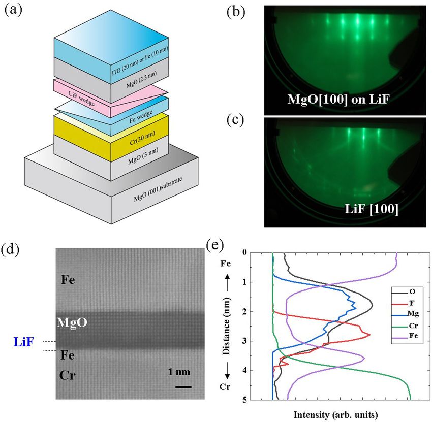
Nozaki et al. NPG Asia Materials (2022)14:5 Page 2 of 7 5
oxygen;4,5 therefore, the film thickness needs to be thin (device A) for evaluation of the magnetic properties by
enough to overcome the demagnetization energy of the polar-MOKE measurements. For the STEM observations
recording layer. Enhancement of the interface magnetic and TMR measurements, a 10 nm-thick Fe reference layer
anisotropy is important to realize a high Δ value, not only (device B) was deposited on the MgO(001) tunneling bar-
for spin-transfer-torque MRAMs6 but also for voltage- rier at a substrate temperature of 200 °C followed by
controlled MRAMs7,8. Several approaches have been annealing at 250 °C. Finally, the top Fe layer was covered by
proposed for the improvement in Δ utilizing the interface sputter-deposited Ta (5 nm)/Ru (7 nm) capping layers. MTJ
PMA, such as the introduction of a heavy metal buffer9,10, devices were prepared by conventional optical lithography,
a nitrogen-doped buffer11, an MgO-double barrier struc- ion-milling, and lift-off processes. The cross-sectional area
ture12,13, a spinel MgAl2O4 barrier14, and heavy metal of the junction was designed to be 2 × 6 μm2. The TMR
doping in a thin ferromagnetic layer15,16. curves were measured with a conventional direct-current
In this work, we propose a new approach to enhance the two-probe method under the application of in-plane mag-
interface PMA and TMR. This is done by introducing an netic fields at room temperature.
ultrathin LiF layer at the Fe/MgO interface. Increases in
the interface PMA using fluoride have been reported for Results and discussion
polycrystalline Ta/CoFeB/AlF3 and Ta/CoFeB/MgF2 Epitaxial growth of LiF(001) on Fe(001) and MgO(001) on
structures17 compared with conventional oxide dielectric LiF(001) was confirmed by reflection high-energy electron
layers, such as Al2O3 and HfO2; however, the TMR diffraction (RHEED) with sharp streaks, as shown in Fig. 1b,
properties were not investigated. To realize both c. Here, the incident electron beam is parallel to the [100]
improved PMA and TMR properties, we focus on a LiF/ azimuth of the MgO substrate. The lattice constant of LiF
MgO bilayer tunneling barrier. There have been a few (a = 0.402 nm) is smaller than that of MgO (a = 0.421 nm)
reports of the TMR properties for structures with LiF and matches wellpffiffiffiwith that of Fe (a = 0.286 nm) when it is
tunneling barriers, both in experiments18–20 and using rotated by 45° ( 2a = 0.404 nm). Single crystal lattices with
first-principles calculations;21 however, a large TMR effect flat interfaces were also confirmed by high-angle annular
has not yet been achieved at room temperature. Even for dark-field scanning transmission electron microscopy
other fluoride materials, such as MgF2, a large TMR effect (HAADF-STEM) imaging (Fig. 1d). For the STEM obser-
has not yet been realized in MTJ structures22,23, although vation, we used an MTJ structure with a thicker LiF layer
their availability has been discussed in granular systems24–26. consisting of Cr/Fe(0.7 nm)/LiF(0.4 nm)/MgO(2.3 nm)/Fe
For this purpose, we prepared fully epitaxial Fe(001)/LiF (10 nm) to monitor the concentration distribution of
(001)/MgO(001)/Fe(001) structures. Here, LiF/MgO fluorine (F) more clearly. Figure 1e shows the intensity
works as a bilayer tunneling barrier. An enhancement of profiles of electron energy-loss spectroscopy (EELS) of
the interface PMA was confirmed when the ultrathin LiF oxygen (O), fluorine (F), magnesium (Mg), chromium (Cr),
layer was inserted between the ultrathin Fe and MgO. The and iron (Fe). We can see a clear fluorine peak between the
intrinsic interface PMA energy, Ki,0, increased to 2.8 mJ/ Fe and MgO layers. There may be some finite intermixing
m2, which is approximately 1.4 times larger than that of a at the LiF/MgO interface due to the smaller signals of Mg
standard Fe/MgO interface (2.0 mJ/m2). We also observed and O in the LiF layer; however, we can expect that the
an increase in the TMR ratio when LiF was inserted, interface PMA properties, as discussed below, might be
suggesting that a coherent tunneling process was main- dominated by the Fe/LiF interface.
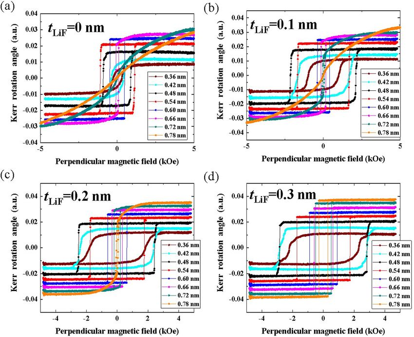
tained in the LiF/MgO bilayer. The Fe thickness dependencies of the polar MOKE
hysteresis curves for device A are shown in Fig. 2. The LiF
Materials and methods thicknesses, tLIF, were designed to be (a) 0 nm, (b) 0.1 nm,
Figure 1a shows a schematic illustration of the sample (c) 0.2 nm and (d) 0.3 nm. For the standard Fe/MgO
structure, which is a multilayer stack consisting of a Cr/Fe structure, we observed a transition of the magnetic easy
wedge (tFe = 0–1.0 nm)/LiF wedge (tLiF = 0–0.3 nm)/MgO axis from perpendicular to in-plane at approximately
(2.3 nm)/top electrode grown on an MgO(001) substrate by tFe = 0.66 nm. On the other hand, with the LiF layer, an
a combination of molecular beam epitaxy and sputtering increase in the transition thickness was observed with an
techniques. A 5 nm-thick MgO(001) seed layer and a enlargement in the coercivity. The perpendicular mag-
30 nm-thick Cr(001) buffer layer were deposited at 200 °C netic easy axis was maintained even at approximately
followed by annealing at 800 °C. An ultrathin Fe(001) layer tFe = 0.8 nm for the case with tLiF = 0.3 nm, as shown in
was grown at 150 °C and annealed at 250 °C. After the Fig. 2d, indicating an enhancement in the PMA.
substrate temperature was lowered to room temperature, For a detailed quantitative evaluation of the PMA
ultrathin LiF(001) and MgO (001) layers were deposited energy, we prepared orthogonally magnetized MTJ
followed by annealing at 250 °C. The MgO surface was structures (device B), which have a perpendicularly mag-
capped with a sputter-deposited 20 nm-thick ITO electrode netized ultrathin Fe layer sandwiched between Cr and LiF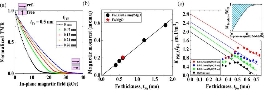
Nozaki et al. NPG Asia Materials (2022)14:5                                                                                     Page 3 of 7 5

 Fig. 1 Magnetic tunnel junction with a LiF/MgO bilayer tunnel barrier. a Schematic of the prepared heterostructures consisting of a Cr(30 nm)/
 Fe wedge (tFe = 0–1.0 nm)/LiF wedge (tLiF = 0–0.3 nm)/top electrode grown on a MgO(001) substrate. RHEED patterns for b MgO[100] grown on LiF
 and c LiF[100] grown on Fe. d Cross-sectional HAADF-STEM image and e EELS intensity profiles across the interface for each atomic species in the Cr/
 Fe(0.6 nm)/LiF(0.4 nm)/MgO(2.3 nm)/Fe(10 nm) structure.

(or MgO) and an in-plane magnetized Fe layer of 10 nm as                    ratio. The saturation property of the TMR curves reflects
a top reference layer. Application of an in-plane magnetic                  the perpendicular anisotropy fields for the ultrathin Fe
field (Hex) tilts the magnetization of the free layer in the                 layer. With increasing LiF thickness, a systematic increase
film plane, while that of the reference layer stays in the                   in the saturation field is observed. This tendency is con-
film plane, as illustrated in Fig. 3a. Therefore, we can                     sistent with that observed in the polar-MOKE measure-
evaluate the magnetization process of the free layer in the                 ments. With LiF layers thicker than 0.2 nm, the saturation
magnetic hard axis direction under in-plane magnetic                        fields reach up to 30 kOe, which is approximately twice
fields. The LiF thickness dependence of the TMR curves is                    that of a standard Fe/MgO MTJ.
shown in Fig. 3a for a fixed Fe thickness of 0.5 nm. Here,                     From these TMR curves, we can calculate the effective
the vertical axis is normalized by the maximum (Hex =                       PMA energy, KPMA, for each Fe thickness using the fol-
0 Oe) and minimum (Hex = 40 kOe) resistances to avoid                       lowing evaluation process:27 Since the tunneling con-
the influence of the bias voltage dependence of the TMR                      ductance depends on the relative angle, θ between the two
Nozaki et al. NPG Asia Materials (2022)14:5                                                                                 Page 4 of 7 5

 Fig. 2 Influence of LiF layer insertion at the interface on the magnetic hysteresis curves of an ultrathin Fe layer. Fe thickness dependence of
 polar-MOKE hysteresis curves for structures a without LiF, with b tLiF = 0.1 nm, c tLiF = 0.2 nm, and d tLiF = 0.3 nm.

ferromagnetic layers, the ratio of the in-plane component                 perform a systematic evaluation of KPMA as a function of
of the magnetization for the ultrathin Fe layer, Min-plane to             the Fe and LiF thicknesses. The saturation magnetization,
the saturation magnetization, MS is calculated from the                   MS, was independently measured using a vibrating-sample
following relationship:                                                   magnetometer (VSM). Figure 3b shows the Fe thickness
                                                                          dependence of the magnetic moment for Cr/Fe(tFe)/LiF
    Minplane           R90  RðθÞ RP                                     (0.2 nm)/MgO(2.3 nm)/ITO structures with a sample size
              ¼ cos θ ¼                                           ð1Þ
      MS                   RðθÞ R90  RP                                  of 1 cm × 2 cm. A linear increase in the magnetic moment
                                                                          was confirmed with increasing tFe. A distinct magnetic
where RP and R90 are the MTJ resistances in the parallel                  dead layer was not observed in this structure. The value of
and orthogonal configurations, respectively. R(θ) is the                   MS was evaluated to be approximately 2.0 T, which is
MTJ resistance when the magnetization of the Fe free                      comparable to that of a standard Cr/Fe/MgO structure, as
layer is tilted toward the in-plane direction at angle θ from             shown by the red star in Fig. 3b. These results imply that a
the film plane by the application of an in-plane magnetic                  pure ultrathin Fe layer is maintained at the Fe/LiF
field. KPMA can be evaluated by calculating the area above                 interface even after a post-annealing process.
the normalized Min-plane/MS (Hex) curve with the MS                         Figure 3c presents the dependence of KPMAtFe on the Fe
value obtained by other measurements (shaded area in the                  thickness for different tunneling barriers consisting of a
inset of Fig. 3c). By using the wedge-shaped MTJ, we can                  single MgO (2.5 nm) layer and LiF (0.1–0.3 nm)/MgO
Nozaki et al. NPG Asia Materials (2022)14:5 Page 5 of 7 5
Fig. 3 Evaluation of the interface perpendicular magnetic anisotropy in MTJ structures. a The LiF thickness, tLiF, dependence of normalized
TMR curves measured under an in-plane magnetic field with a fixed Fe thickness of tFe = 0.5 nm. b Nominal Fe thickness dependence of the
magnetic moment for the sample with tLiF = 0.2 nm (sample size: 1 cm × 2 cm). No clear degradation in the magnetic moment was observed even in
the ultrathin Fe thickness region (tFe < 1.0 nm). The red star shows reference data obtained in a standard Fe/MgO structure. c KPMAtFe as a function of
Fe thickness for MTJs with different barrier structures consisting of a single MgO layer (black dots), LiF(0.1 nm)/MgO layers (green dots), LiF(0.2 nm)/
MgO layers (blue dots), and LiF(0.3 nm)/MgO layers (red dots). Linear fitting was conducted to evaluate the Ki,0 value in the thick Fe region, where a
linear relation was observed, as shown by solid lines. The inset shows an example of a normalized Min-plane (Hex) curve obtained from the TMR curve
for the MTJ with tFe = 0.52 nm and without a LiF layer.
(2.3 nm) bilayers. The effective magnetic anisotropy other hand, LiF is a suitable material even from the
energy, KPMA, can be expressed by the following phe- viewpoint of the TMR properties, as discussed next. For
nomenological expression: KV, all structures show almost the same values of
approximately −0.5 MJ/m3, which is comparable to that
1 Ki;0 observed in the standard Fe/MgO15. This suggests that LiF
KPMA ¼ KV μ0 MS2 þ ð2Þ
2 tFe insertion has little influence on the volume anisotropy.
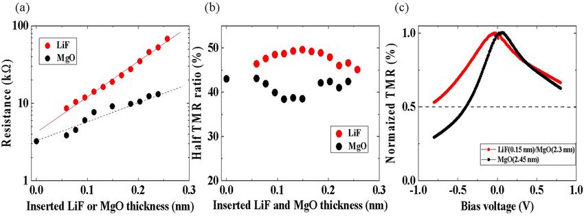
Figure 4a shows the LiF thickness dependence of the
where KV and μ0 are the volume anisotropy and vacuum tunneling resistance in a parallel magnetization config-
permeability, respectively. Ki,0 represents the intrinsic uration (red dots). Here, the Fe thickness is fixed at
interface PMA, which can be evaluated from the intercept 0.54 nm. An exponential increase in the resistance is
in a plot of KPMAtFe versus tFe. The expected linear observed, indicating that the LiF layer also works as an
relationship was confirmed for tFe > 0.5 nm, whereas a additional tunneling barrier. The rate of increase in the
reduction in KPMAtFe occurred in the thinner Fe thickness resistance is larger than that of a single MgO barrier
regions. This trend is consistent with the Fe thickness (shown by black dots in Fig. 4a), probably due to the
dependence of the coercivity change observed in Fig. 2. larger energy band gap of LiF (8.7 eV) compared to that of
The possible origin of the deviation may relate to the MgO (7.8 eV).
magnetoelastic effect, as discussed in previous works28,29. The LiF and MgO thickness dependence of the TMR
Ki,0 is the representative value expressing the amplitude of ratio is shown in Fig. 4b. Here, the vertical axis represents
interface magnetic anisotropy at zero Fe thickness. For the half of the full TMR ratio due to the orthogonal magne-
standard Fe/MgO interface, the Ki,0 value was evaluated to tization configuration in our MTJs. For the standard Fe/
be approximately 2.0 mJ/m2 from the linear fitting in the MgO MTJ, the TMR ratio decreases gradually and
thicker tFe region. This is comparable to the previously reaches a minimum at an MgO thickness of approxi-
reported values29,30. Ki,0 is enhanced systematically by mately 0.15 nm; however, it recovers again with increasing
inserting a LiF layer and reaches approximately 2.8 mJ/m2 MgO thickness. This trend may come from the oscillatory
at tLiF = 0.3 nm. A similar enhancement in the PMA was variation in TMR as a function of MgO thickness reported
also observed when other fluoride materials, such as MgF2 in the previous work1. Interestingly, the LiF/MgO bilayer
and CaF2, were inserted (not shown here). Therefore, the MTJ shows the opposite trend, i.e., the TMR ratio
origin of the improved PMA seems to come from the increases gradually and reaches a maximum at a LiF
band hybridization between Fe and fluorine. However, we thickness of approximately 0.15 nm, followed by a
could not obtain a large TMR effect when MgF2 or CaF2 decrease with increasing LiF thickness. In the LiF thick-
layers were inserted at the Fe/MgO interface. On the ness ranges investigated in this work, the TMR ratios areNozaki et al. NPG Asia Materials (2022)14:5 Page 6 of 7 5
Fig. 4 Influence of the LiF layer insertion on the TMR properties. LiF and MgO thickness dependencies of a tunneling resistance in a parallel
magnetization configuration and b TMR ratio for the MgO(tMgO)/MgO(2.3 nm) layers (black dots) and LiF(tLiF)/MgO(2.3 nm) layers (red dots),
respectively. c Comparison of bias voltage dependence of normalized TMR ratio for the MTJs with an MgO(2.45 nm) barrier (black dots) and a LiF
(0.15 nm)/MgO(2.3 nm) bilayer barrier (red dots).
basically larger than that of the Fe/MgO standard struc- through the LiF/MgO bilayer tunneling barrier, suggest-
ture. We need further investigation over a wider range of ing that the coherent tunneling process of the Δ1 band
LiF thicknesses to investigate the physical origin of the was maintained in the LiF layer. Interface engineering
observed tendency; nevertheless, we can at least conclude using an ultrathin LiF layer is a new approach to devel-
that the coherent tunneling process of the Δ1 band in the oping MTJs with high thermal stability while maintaining
Fe(001) electrode is maintained even in the ultrathin LiF a large TMR effect.
(001) layer as well as at the MgO(001) barrier, which can
Acknowledgements
provide a large TMR effect. This work was partly based on results obtained from a project, JPNP16007,
The bias voltage dependence of the TMR for two types commissioned by the New Energy and Industrial Technology Development
of tunneling barriers is compared for structures with a Organization (NEDO), Japan. The authors thank M. Endo, H. Ohmori, Y. Sato,
Y. Kageyama, L. Sakai, K. Hiraga, Y. Higo, and M. Hosomi of the Sony
single MgO (2.45 nm) layer and a LiF (0.15 nm)/MgO Semiconductor Solutions Corporation, S. Miwa and S. Sakamoto of the Univ. of
(2.3 nm) bilayer in Fig. 4c. The MgO single barrier exhi- Tokyo, and H. Imamura, Y. Kitaoka, T. Taniguchi, and Y. Hibino of AIST for their
bits an asymmetric bias voltage dependence (black dots), fruitful discussions.
as observed in the previous report1. At negative bias
Author contributions
voltages, where it is sensitive to the electronic structure at T.N. planned and performed the sample fabrication, measurement, and data
the bottom Fe/MgO interface, the bias voltage at which analysis. T.N., M.K., T.Y, A.S., K.Y., H.K., A.F., and S.Y. developed techniques for
the TMR ratio becomes half of the maximum value is deposition, microfabrication, and measurements. T.N. wrote the manuscript
with review and input from T.N., M.K., T.Y, A.S., K.Y., H.K., and A.F. S.Y. planned
approximately half that in the positive bias voltage and supervised the project. All authors contributed to the planning, discussion,
direction. The cause of this degradation can be explained and analysis of this research.
by structural defects, such as dislocations and lattice
Conflict of interest
distortions31. On the other hand, the bias voltage The authors declare no conflict of interest.
dependence is relatively symmetric when an ultrathin LiF
layer is inserted at the interface (red dots). This tendency Publisher’s note
Springer Nature remains neutral with regard to jurisdictional claims in
can be explained by an improvement in the lattice
published maps and institutional affiliations.
matching at the Fe/LiF interface, similar to that discussed
in Fe/MgAl2O4 MTJs31. Received: 9 August 2021 Revised: 4 December 2021 Accepted: 14
December 2021
Conclusion
In summary, the effect of inserting an ultrathin LiF layer
at the Fe/MgO interface on the PMA and TMR properties
References
of an MTJ structure was investigated. With a LiF layer, the
1. Yuasa, S., Nagahama, T., Fukushima, A., Suzuki, Y. & Ando, K. Giant room-
interface PMA was enhanced with a large Ki,0 value of temperature magnetoresistance in single-crystal Fe/MgO/Fe magnetic tunnel
approximately 2.8 mJ/m2. We also observed a large TMR junctions. Nat. Mater. 3, 868–871 (2004).Nozaki et al. NPG Asia Materials (2022)14:5 Page 7 of 7 5
2. Parkin, S. S. et al. Giant tunnelling magnetoresistance at room temperature 17. Pankieiev, M. & Kita, K. Effects of oxide replacement with fluoride at the CoFeB
with MgO (100) tunnel barriers. Nat. Mater. 3, 862–867 (2004). interface on interface magnetic anisotropy and its voltage control. AIP Adv. 8,
3. Ikeda, S. et al. A perpendicular-anisotropy CoFeB–MgO magnetic tunnel 055901 (2018).
junction. Nat. Mater. 9, 721–724 (2010). 18. Xue, Q. et al. Tunnel magnetoresistance in epitaxial (100)-oriented FeCo/LiF/
4. Yang, H. X. et al. First-principles investigation of the very large perpendicular FeCo magnetic tunnel junctions. Appl. Phys. Lett. 109, 192407 (2016).
magnetic anisotropy at Fe|MgO and Co|MgO interfaces. Phys. Rev. B 84, 19. Narayananellore, S. K., Doko, N., Matsuo, N., Saito, H. & Yuasa, S. Fabrication of
054401 (2011). magnetic tunnel junctions with a single-crystalline LiF tunnel barrier. Jpn. J.
5. Okabayashi, J. et al. Perpendicular magnetic anisotropy at the interface Appl. Phys. 57, 04FN04 (2018).
between ultrathin Fe film and MgO studied by angular-dependent X-ray 20. Liu, F. et al. Resonant TMR inversion in LiF/EuS based spin-filter tunnel junc-
magnetic circular dichroism. Appl. Phys. Lett. 105, 122408 (2014). tions. AIP Adv. 6, 085004 (2016).
6. Ikeda, S. et al. Recent progress of perpendicular anisotropy magnetic tunnel 21. Vlaic, P., Burzo, E. & Carva, K. Are insulating LiF barriers relevant for spin-
junctions for nonvolatile VLSI. Spin 02, 1240003 (2012). polarized tunnelling applications? Insights from first-principles calculations. J.
7. Amiri, P. K. et al. Electric-Field-Controlled Magnetoelectric RAM: Progress, Phys. D: Appl. Phys. 49, 305302 (2016).
Challenges, and Scaling. IEEE Trans. Magn. 51, 3401507 (2015). 22. Mitani, S., Moriyama, T. & Takanashi, K. Structure and tunnel magnetoresistance
8. Nozaki, T. et al. Recent progress in the voltage-controlled magnetic anisotropy in Fe/MgF[sub 2]/Co junctions with an oxide seed layer on an Fe bottom
effect and the challenges faced in developing voltage-torque MRAM. Micro- electrode. J. Appl. Phys. 91, 7200 (2002).
machines 10, 327 (2019). 23. Harada, K., Makabe, K. S., Akinaga, H. & Suemasu, T. Room temperature
9. Worledge, D. C. et al. Spin torque switching of perpendicular Ta∣CoFeB∣MgO- magnetoresistance in Fe3Si/CaF2/Fe3Si MTJ epitaxially grown on Si(111). J.
based magnetic tunnel junctions. Appl. Phys. Lett. 98, 022501 (2011). Phys.: Conf. Ser. 266, 012088 (2011).
10. Pai, S.-F. et al. Enhancement of perpendicular magnetic anisotropy and 24. Furubayashi, T. & Nakatani, I. Giant magnetoresistance in granular Fe–MgF2
transmission of spin-Hall-effect-induced spin currents by a Hf spacer layer in films. J. Appl. Phys. 79, 6258 (1996).
W/Hf/CoFeB/MgO layer structures. Appl. Phys. Lett. 104, 082407 (2014). 25. Kobayashi, N., Ohnuma, S., Masumoto, T. & Fujimori, H. (Fe–Co)–(Mg-fluoride)
11. Sinha, J. et al. Enhanced interface perpendicular magnetic anisotropy in Ta| insulating nanogranular system with enhanced tunnel-type giant magne-
CoFeB|MgO using nitrogen-doped Ta underlayers. Appl. Phys. Lett. 102, toresistance. J. Appl. Phys. 90, 4159–4162 (2001).
242405 (2013). 26. Ono, K et al. Electrical Conduction and Tunneling Magnetoresistance of Fe,Co/
12. Sato, H. et al. Perpendicular-anisotropy CoFeB−MgO magnetic tunnel junc- MgF2 Granullar Multilayers. Jpn. J. Appl. Phy. 41, 97–102 (2002).
tions with a MgO/CoFeB/Ta/CoFeB/MgO recording structure. Appl. Phys. Lett. 27. Shiota, Y. et al. Quantitative evaluation of voltage-induced magnetic aniso-
101, 022414 (2012). tropy change by magnetoresistance measurement. Appl. Phys. Exp. 4, 043005
13. Kubota, H. et al. Enhancement of perpendicular magnetic anisotropy in FeB (2011).
free layers using a thin MgO cap layer. J. Appl. Phys. 111, 07C723 (2012). 28. Bloemen, P. J. H., Johnson, M. T., den Broeder, F. J. A. & de Vries, J. J. Magnetic
14. Xiang, Q., Mandal, R., Sukegawa, H., Takahashi, Y. K. & Mitani, S. Large per- anisotropy in metallic multilayers. Rep. Prog. Phys. 59, 1409–1458 (1996).
pendicular magnetic anisotropy in epitaxial Fe/MgAl2O4(001) hetero- 29. Nozaki, T. et al. Large voltage-induced changes in the perpendicular magnetic
structures. Appl. Phys. Exp. 11, 063008 (2018). anisotropy of an MgO-based tunnel junction with an ultrathin Fe Layer. Phys.
15. Nozaki, T. et al. Highly efficient voltage control of spin and enhanced inter- Rev. Appl. 5, 044006 (2016).
facial perpendicular magnetic anisotropy in iridium-doped Fe/MgO magnetic 30. Koo, J. W. et al. Large perpendicular magnetic anisotropy at Fe/MgO interface.
tunnel junctions. NPG Asia Mater. 9, e451–e451 (2017). Appl. Phys. Lett. 103, 192401 (2013).
16. Nozaki, T. et al. Enhancement in the interfacial perpendicular magnetic ani- 31. Sukegawa, H. et al. Tunnel magnetoresistance with improved bias voltage
sotropy and the voltage-controlled magnetic anisotropy by heavy metal dependence in lattice-matched Fe/spinel MgAl2O4/Fe(001) junctions. Appl.
doping at the Fe/MgO interface. APL Mater. 6, 026101 (2018). Phys. Lett. 96, 212505 (2010).You can also read