Elliptical Supercritical Lens for Shaping Sub-Diffractive Transverse Optical Needle - MDPI
←
→
Page content transcription
If your browser does not render page correctly, please read the page content below
nanomaterials

Article
Elliptical Supercritical Lens for Shaping Sub-Diffractive
Transverse Optical Needle
Jian Lei † , Minghui Wang † , Jin Wu, Hui Duan, Kun Zhang, Sicong Wang, Yaoyu Cao , Xiangping Li *
and Fei Qin *

 Guangdong Provincial Key Laboratory of Optical Fiber Sensing and Communications, Institute of Photonics
 Technology, Jinan University, Guangzhou 510632, China
 * Correspondence: xiangpingli@jnu.edu.cn (X.L.); qinfei@jnu.edu.cn (F.Q.)
 † These authors contributed equally to this work.

 Abstract: Supercritical lens can create a sub-diffraction-limited focal spot in the far field, providing a
 promising route for the realization of label-free super-resolution imaging through the point scanning
 mechanism. However, all of the reported supercritical lenses have circular shape configurations,
 and produce isotropic sub-diffraction-limited focal spots in the focal plane. Here, we propose and
 experientially demonstrate a sub-diffraction transverse optical needle by using an elliptical supercriti-
 cal lens. Through breaking the circular symmetry and introducing ellipticity to the lens, a uniform
 sub-diffractive transverse optical needle with lateral length and width of 6λ/NA and 0.45λ/NA,
 respectively, was successfully created in the focal plane. Further, elliptical sector-shape cutting with
 an optimized apex angle of 60 degrees can lead to suppressed subsidiary focusing for improved
 uniformity and condensed field intensity of the transverse optical needle. The demonstration of
 sub-diffractive transverse optical needle with a high aspect ratio (length to width ratio) of 13:1 may
 find potential applications in line-scanning microscopy for video-rate label-free super-resolution
 imaging, and also enable advances in the fields from laser manufacturing to optical manipulation.

 Keywords: planar diffracted lens; elliptical supercritical lens; sub-diffractive limited

Citation: Lei, J.; Wang, M.; Wu, J.;
Duan, H.; Zhang, K.; Wang, S.; Cao,
Y.; Li, X.; Qin, F. Elliptical
 1. Introduction
Supercritical Lens for Shaping Line scanning confocal microscopy is a cutting-edge technology for achieving high
Sub-Diffractive Transverse Optical imaging throughput while retaining the essential advantage of conventional confocal
Needle. Nanomaterials 2023, 13, 242. microscopy [1–3]. By using a transverse optical needle to replace the isotropic focal spot,
https://doi.org/10.3390/ the image acquisition rates up to 100 fps have been successfully achieved by line-scanning
nano13020242 confocal microscopy [4]. With such a system, the imaging process can significantly release
Academic Editor: Dong-Wook Kim the compromise between the imaging quality, field of view, and acquisition speed, then
 across the obstacle of in vivo imaging of living tissues. The line-scanning working manner
Received: 15 December 2022 can also be applied in the fields of light-sheet microscopy [5] and high-definition fluorescent
Revised: 31 December 2022
 micro-optical sectioning tomography, etc. [6]. However, the lateral size of the transverse
Accepted: 3 January 2023
 optical needle created by the classical technique is bounded by the diffraction limit barrier;
Published: 5 January 2023
 therefore, the imaging capability of the line-scanning confocal microscopy cannot meet the
 advanced requirement of sub-diffraction-limited property in biological imaging process. In
 addition, the transverse optical needle is usually created by utilizing the cylindrical lens
Copyright: © 2023 by the authors.
 and objective lens, making the line-scanning confocal system bulky and with a low level
Licensee MDPI, Basel, Switzerland. of integration. To eliminate these obstacles, one possible approach relies on the planar
This article is an open access article diffractive metalens, which could modulate the intensity distribution on the focal plane in
distributed under the terms and light of specific requirements, and could also remarkably simplify the bulky optical system.
conditions of the Creative Commons Sub-diffraction-limited planar metalens, represented by the superoscillatory lens (SOL)
Attribution (CC BY) license (https:// and supercritical lens (SCL), have attracted considerable attention for their extraordinary light
creativecommons.org/licenses/by/ modulation capability and have rapidly advanced in terms of performance and function-
4.0/). ality [7–13]. Through delicately controlling the interference effect, a sub-diffraction-limited

Nanomaterials 2023, 13, 242. https://doi.org/10.3390/nano13020242 https://www.mdpi.com/journal/nanomaterials
Nanomaterials 2023, 13, 242 2 of 15

 focal spot can be formed in the focal plane, then inspiring versatile applications in the as-
 pect of super-resolution telescope, nanometrology, optical nanofabrications, etc. [14,15]. It
 is particularly important to emphasize that the sub-diffraction-limited focal spot could also
 be used for the label-free super-resolution imaging through combining it with the confocal
 microscopy configurations [16–18]. The superior imaging property and optical sectioning
 capability was realized through a point-by-point scanning across the specimen. However,
 all the reported SOL and SCL produced an isotropic sub-diffraction-limited focal spot in the
 focal plane, due to their circular symmetric configuration. Thus, the SOL- and SCL-based
 super-resolution imaging processes have the similar deficiency with conventional point-
 scanning confocal microscopy, as well as its derivative technologies, in terms of low imaging
 throughput [19–22]. Therefore, expanding the isotropic sub-diffraction limited focal spot to a
 sub-diffraction limited transverse optical needle may potentially bring about benefits for the
 realization of line-scanning super-resolution imaging with high throughput.
 In this work, we proposed and experimentally demonstrated a new type of super-
 critical lens (SCL) with an elliptical configuration for shaping a transverse optical needle
 in the focal plane with lateral size in the sub-diffraction-limited domain. Such a lens
 with a binary amplitude-type elliptical configuration can be conveniently fabricated by
 the standard nanofabrication technique. Through controlling the ellipticity of the lens
 configuration (aspect ratio of long axis to short axis), the length of the transverse optical
 needle can be reasonably controlled. A transverse optical needle with a lateral length of 7λ
 and sub-diffractive width of 0.45λ/NA (NA is the numerical aperture) has been success-
 fully demonstrated. Further, elliptical sector-shape cutting with an optimized apex angle
 of 60 degrees can suppress subsidiary focusing for improved uniformity and condensed
 field intensity of the transverse optical needle. Comparing it with the cylindrical planar
 metalens, our elliptical supercritical lens achieved eight times higher intensity in the needle
 region under the same optimization conditions. Such an elliptical supercritical lens may
 pave the path for the realization of line-scanning confocal microscopy with video-rate
 super-resolution imaging capability. Our demonstration may also attractively offer the
 prospect of advances in the fields, from laser manufacturing to optical manipulation.

 2. Results
 2.1. Optimization Algorithm for Modified Elliptical SCL
 Ellipse is one of the most fundamental shapes with interesting properties in geometri-
 cal and physical fields. In the optical domain, rays of light originating at one of the foci
 of an elliptical mirror will be converged at the other focus after reflecting off the surface.
 Using this feature, the metal halide lamps used in microscopy are usually equipped with
 elliptical reflectors to generate a concentrated spot of light by embedding the bulb at one
 focus of the ellipse. However, almost all of the reported planar metalenses, including
 zone-plate-type [23–26], metasurface-type [9,27–30] and photosieves-type [31–33], have
 been of circular symmetric topology, and then lead to isotropic sub-diffraction-limited focal
 spots in the focal plane, as shown in Figure 1a. The elliptical configuration has seldom
 been investigated in the construction of a diffractive lens, due to the complicated field
 modulation property. A planar metalens in an ellipse configuration with non-circular
 symmetric topology should produce an anisotropic field distribution on the designed plane,
 as schematically expressed in Figure 1b.
 For a conventional planar metalens with a circular configuration, the structures can be
 easily designed in a cylindrical coordinate system by adopting the Rayleigh–Sommerfeld
 integral method in conjunction with the particle swarm optimization process [11,13,34].
 The field modulation property on the focal plane for each circular belt could be obtained
 through the angular integration over 2π space with a fixed radial length, as shown in
 Figure 1c. However, the topology of an ellipse shape and field intensity distribution of
 the transverse optical needle does not conform to the circular symmetry, and hence, the
 diffraction algorithm in a conventional cylindrical coordinate system needs to be modified
 for this situation. In the mathematical sense, every ellipse with foci on the x-axis can be
semi-major axis length and semi-minor axis length, r is the radius of the original
 and the stretch factor c is the ellipticity of the obtained ellipse, which represents the
 of semi-major axis length to semi-minor axis length as c = a/b.
 2 2 2 2
 + = + = 1,
Nanomaterials 2023, 13, 242 2 2 ( )2 2 3 of 15
 Transforming the standard formula of ellipse from the rectangular coordinat
 the cylindrical coordinate, the radial length rθ from any point on the ellipse with an
 can be derived
 obtained by stretching as:horizontally, while leaving the vertical scale unchanged.
 a circle
 Beginning with a circle center at the origin of coordinates, an ellipse will be created by
 = ⁄√( ∗ )2 + ( )2 ,
 changing every (x, y) on the circle to (cx, y) with a horizontal stretch factor of c (c > 1). Then,
 the obtained ellipse
 wherecan be expressed
 θ indicates as Equation (1),angle
 the counterclockwise wherewitha and b areto
 respect the
 thesemi-major
 x-axis from the lin
 axis length andnecting
 semi-minor axis length, r
 the point on the ellipse to the original point, and the rθ isthe
 is the radius of the original circle, and stretch
 the radial length
 factor c is the ellipticity of the obtained ellipse,
 angle θ, as shown in Figure 1d. which represents the ratio of semi-major
 axis length to semi-minor axis length as c = a/b.

 Figure
 Figure 1. Schematic 1. Schematic
 comparison comparison
 between between
 the circular and the circular
 elliptical and ellipticalofconfiguration
 configuration of planar me
 planar metalens.
 (a) shaping an isotropic focal spot by a circular planar metalens; (b) shaping
 (a) shaping an isotropic focal spot by a circular planar metalens; (b) shaping a transverse optical a transverse
 needle in the focal plane by an elliptical planer metalens, where a and b are the semi-min
 needle in the focal plane by an elliptical planer metalens, where a and b are the semi-minor and
 semi-major axis length; (c) parameters of a planar metalens with circular configuration, wh
 semi-major axis length; (c) parameters of a planar metalens with circular configuration, where r is
 the radius of each transparent belt, and θ is the azimuthal angle; (d) parameters of a planar me
 the radius of each transparent belt, and θ is the azimuthal angle; (d) parameters of a planar metalens
 with elliptical configuration, where the rθ_in and rθ_out indicate the inner and outer radial length of a
 transparent elliptical belt at the angle θ.

 x2 y2 x2 y2
 2
 + 2 = 2
 + 2 = 1, (1)
 a b (cr ) r
 Transforming the standard formula of ellipse from the rectangular coordinate into the
 cylindrical coordinate, the radial length rθ from any point on the ellipse with angle θ can be
 derived as: q
 rθ = a/ (c ∗ sinθ )2 + (cosθ )2 , (2)
 where θ indicates the counterclockwise angle with respect to the x-axis from the line
 connecting the point on the ellipse to the original point, and the rθ is the radial length at
 the angle θ, as shown in Figure 1d.
 Based on the above analysis, a modified Rayleigh–Sommerfeld (RS) diffraction integral
 method in a cylindrical coordinate applied to the ellipse pattern has been developed, as
 expressed in Equation (3). Comparing with the RS equation applied to the circular shape,
 the integral limits of the radius have been changed from a fixed value to an angle-dependent
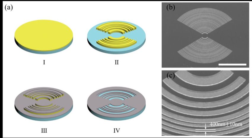
with elliptical configuration, where the rθ_in and rθ_out indicate the inner and outer radial length of a
 transparent elliptical belt at the angle θ.

 Based on the above analysis, a modified Rayleigh–Sommerfeld (RS) diffraction inte-
Nanomaterials 2023, 13, 242 gral method in a cylindrical coordinate applied to the ellipse pattern has been developed, 4 of 15

 as expressed in Equation (3). Comparing with the RS equation applied to the circular
 shape, the integral limits of the radius have been changed from a fixed value to an angle-
 dependent variable
 variable value value according
 according the elliptical
 the elliptical equationequation
 for eachfor each transparent
 transparent belt in belt in cy-
 cylindrical
 lindrical coordinates.
 coordinates.
 Z _ Z 2π
 2
 11 rθ_out
 iknR−−11
 U ( ,
 (ρ, θ, ,z )
 ) ==−− ∫ ∫ U00(
 (r θ,, )
 θ ) exp( )
 exp(iknR) ∗∗ ∗∗
 zr θ
 dr θ
 dθ (3)(3)
 2 rθ_in
 2π _ 00 R33

 where
 whereUU00isisthe theincidence
 incidencelight lightfield,
 field,RRisisthe
 thedistance
 distancebetween
 betweentwotwopoints
 pointsininlens
 lensplane
 plane
 and focal plane, r and r indicate the inner and outer radial length
 and focal plane, rθ_in and rθ_out indicate the inner and outer radial length of a transparent
 θ_in θ_out of a transparent
 elliptical
 ellipticalbelt
 beltatatthe
 theangle
 angleθ,θ,respectively.
 respectively.Combined
 Combinedwith withthetheparticle
 particleswarm
 swarmoptimization
 optimization
 algorithm,
 algorithm,aabinary
 binaryamplitude-type
 amplitude-typeelliptical
 ellipticalSCL
 SCLcould
 couldbebesuccessfully
 successfullydesigned
 designedthrough
 through
 tuning
 tuningthetheposition
 positionand andwidth
 widthof ofeach
 eachelliptical
 ellipticalbelt,
 belt,as
 as schematically
 schematically shown
 shown in in Figure
 Figure 2a-
 2a–I.
 I.The
 Thedetailed
 detailedanalysis
 analysisisisshown
 shownininAppendix
 AppendixA.1 A.1and
 andFigure
 FigureA1.
 A1.Moreover,
 Moreover, forfor
 anan ellip-
 elliptical
 tical supercritical
 supercritical lens,lens,
 the the length
 length of the
 of the created
 created transverse
 transverse optical
 optical needle
 needle heavily
 heavily relies
 relies ononthe
 the ellipticity of the structures, as the simulation results show in Figure
 ellipticity of the structures, as the simulation results show in Figure A2 in Appendix A. To A2 in Appendix
 A. To balance
 balance the length
 the length and intensity
 and intensity of theoftransverse
 the transverse
 opticaloptical needle,
 needle, the ellipticity
 the ellipticity c =is
 c = 1.2
 1.2 is selected
 selected in theinlens
 the design.
 lens design.

 Figure
 Figure2.2.Comparison
 Comparisonofoflight
 lightfield
 fielddistribution
 distributionbetween
 betweenelliptical
 ellipticalSCL
 SCLwith
 withdifferent
 differentsector-shape
 sector-shape
 cutting. (a-I,b-I,c-I,d-I) Scheme of the elliptical supercritical lens with cutting
 cutting. (a-I,b-I,c-I,d-I) Scheme of the elliptical supercritical lens with cutting apex angle
 apex ofof
 angle 0 deg,
 0 deg,
 20
 20 deg, 40 deg, and 60 deg, respectively; (a-II,b-II,c-II,d-II) the field distribution in the x-zplane
 deg, 40 deg, and 60 deg, respectively; (a-II,b-II,c-II,d-II) the field distribution in the x-z plane
 with apex angle of the sector shape from 0 deg to 60 deg; (a-III,b-III,c-III,d-III) normalized intensity
 with apex angle of the sector shape from 0 deg to 60 deg; (a-III,b-III,c-III,d-III) normalized intensity
 profiles along the optical axis for the corresponding elliptical SCL with different cutting sector. As
 profiles along the optical axis for the corresponding elliptical SCL with different cutting sector. As the
 green dash line shows, the subsidiary focusing effect can be significantly suppressed while the apex
 angle of the sector-shape cutting region increases from 0 deg to 60 deg.

 The simulated focusing properties of an elliptical SCL with a focal length of 20 µm for
 parameter analysis purposes is shown in Figure 2aI–aIII. The illuminating light we used in
 the simulation is a 633 nm linear polarized laser with polarization direction along the major
 axis of the ellipse. As the field intensity in the XOZ plane depicted in Figure 2aII shows,

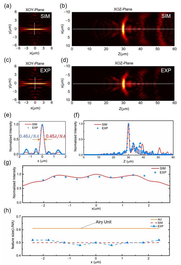
Nanomaterials 2023, 13, 242 5 of 15

 a transverse optical needle can be successfully created at the focal plane of z = 20 µm, as
 marked by the white dash line. However, a series of subsidiary focused light field appears
 around the designed transverse needle, which severely deteriorates the uniformity in the
 optical needle region and the purity along the optical axis, as shown in panel III. Such
 an effect can mainly be attributed to the elliptical geometric configuration. Ellipse shape
 has an angle-dependent variable radial length. On each transparent elliptical belt, the
 light field component with the same spatial frequency diffracted from the minor axis and
 major axis directions will be converged on different z positions. Thus, affected by this
 distinguished configuration, the intricate field intensity distribution will be created in the
 far field when an ellipse shape is used to construct a diffractive lens. To eliminate this
 phenomenon, a pair of sector-shape cutting regions are introduced to change the elliptical
 structure morphology. The modified elliptical supercritical lens is schematically shown in
 Figure 2bI–bIII,dI–dIII. As we can see from the simulation results, the subsidiary focusing
 effect can be significantly suppressed, while the apex angle of the sector-shape cutting
 region increases from 0 deg to 60 deg. Although the length of the transverse optical needle
 decreased, the light intensity in the needle region does not have an obvious change. It is
 noted that there are a series of moderate intensity peaks in the region of z = 25 µm to 40 µm.
 Nevertheless, the relative intensity of those peaks is below 0.2, which would not have a
 significant influence on the practical applications. To keep a proper balance between the
 needle length and subsidiary focusing effect, the elliptical sector-shape cutting with an
 apex angle of 60◦ in both sides along the major axis could produce the best performance.
 (For detail, refer to Appendix A.2). In addition, the modified elliptical SCL also shows
 additional benefits in the aspect of uniformity of the transverse optical needle.

 2.2. Fabrication and Optical Characterization
 Under the guidance of the above theoretical analysis, a modified elliptical supercriti-
 cal lens conforming to the simulation and experimental conditions was re-designed and
 fabricated, and its capability for shaping the transverse optical needle has been experimen-
 tally validated. The focal length f = 30 µm is chosen for the designed elliptical SCL at a
 wavelength of 633nm, and the numerical apertures are set at NA = 0.85. The entire lens
 consists of 40 transparent elliptical belts, and the radial lengths of the outmost semi-minor
 axis (r) and semi-major axis (cr) are 49.44 µm and 59.33 µm, respectively. The width of the
 transparent elliptical belts is variable, with the smallest value of 0.4 µm. The geometric
 parameters for the designed binary amplitude elliptical SCL is presented in Table A1 in
 Appendix A. The radial length r shown in Table A1 is the semi-minor axis, and the length
 of the semi-major axis for each belt can be written as 1.2r. Since the design pattern has a
 binary amplitude configuration with the smallest feature size of 400 nm, it can be easily
 fabricated by the standard lift-off process. The lens is patterned on the PMMA photoresist
 by electron beam lithography (EBL) firstly. Then, a layer of 100 nm titanium was deposited
 on the pattern by using an electron beam evaporator. After the lift-off process, the final
 supercritical lens with binary amplitude type and elliptical configuration was obtained.
 Figure 3a is the schematic representation of the fabrication procedure; for further details
 about the fabrication process refer to Appendix A.3. The scanning electron microscopy
 image of the fabricated elliptical SCL is shown in Figure 3b. The zoom-in view presented in
 Figure 3c indicates that the fabrication error can be controlled under +/−10nm to guarantee
 the focusing performance without deviation from the theoretical results.
 Optical characterization was carried out by a customized microscope imaging system,
 as schematically shown in Figure A4 in Appendix A.4. A linear polarized He-Ne laser
 with 633 nm wavelength was applied to illuminate the fabricated elliptical SCL from the
 substrate side, then collect the diffracting pattern by a high quantum efficiency CMOS
 camera. The polarization state of the laser beam is set along the x-axis and in line with the
 major axis of the ellipse. The convergent sub-diffraction-limited transverse optical needle
 was formed in the focal plane along the major axis direction. The simulated and measured
 intensity distributions at the focal plane of z = 30 µm away from the SCL are depicted in
Nanomaterials 2023, 13, 242 6 of 15

 Figure 4a–d, which clearly shows that a 4 µm-length (~6λ/NA) transverse optical needle
 in the focal plane has been obtained. Notably, the length of the optical needle depends on
 the size of the geometric dimension of the lens. Even a longer optical needle is possible in
 case a larger-size elliptical supercritical lens and high ellipticity value are selected. The line
 intensity profile in a perpendicular direction to the optical needle is plotted in Figure 4e.
 The lateral size of the transverse optical needle is 0.45λ/NA and 0.46λ/NA in simulation
 and experiment results, respectively, which exhibits a sub-diffraction-limited property. The
 field distribution in the XZ plane of the simulation and experimental results are presented
Nanomaterials 2023, 13, x FOR PEER REVIEW 6 of 15
 in Figure 4b,d. The intensity profile along the white dashed line clearly depicted that the
 transverse optical needle dominates the entire diffraction region, as shown in Figure 4f.

 Figure3.3.
 Figure Schematic
 Schematic representation
 representation of fabrication
 of the the fabrication procedure.
 procedure. (a)fabrication
 (a) The The fabrication
 processprocess
 of ellip-of
 elliptical
 Nanomaterials 2023, tical
 13, x SCL: SCL: (I)
 (I) spin
 FOR PEER spin coating with PMMA a4; (II) EBL patterning; (III) Ti Evaporation; (IV)
 coating with PMMA a4; (II) EBL patterning; (III) Ti Evaporation; (IV) lift off;
 REVIEW lift(b)
 off; 7
 the SEM image of processing structure. Scale Bar: 50 μm; (c) the sectional zoom-in view of
 (b) the SEM image of processing structure. Scale Bar: 50 µm; (c) the sectional zoom-in view of thethe ellip-
 tical SCL. SCL.
 elliptical

 Optical characterization was carried out by a customized microscope imaging sys-
 tem, as schematically shown in Figure A4 in Appendix A.4. A linear polarized He-Ne laser
 with 633 nm wavelength was applied to illuminate the fabricated elliptical SCL from the
 substrate side, then collect the diffracting pattern by a high quantum efficiency CMOS
 camera. The polarization state of the laser beam is set along the x-axis and in line with the
 major axis of the ellipse. The convergent sub-diffraction-limited transverse optical needle
 was formed in the focal plane along the major axis direction. The simulated and measured
 intensity distributions at the focal plane of z = 30 μm away from the SCL are depicted in
 Figure 4a–d, which clearly shows that a 4 μm-length (~6λ/NA) transverse optical needle
 in the focal plane has been obtained. Notably, the length of the optical needle depends on
 the size of the geometric dimension of the lens. Even a longer optical needle is possible in
 case a larger-size elliptical supercritical lens and high ellipticity value are selected. The
 line intensity profile in a perpendicular direction to the optical needle is plotted in Figure
 4e. The lateral size of the transverse optical needle is 0.45λ/NA and 0.46λ/NA in simula-
 tion and experiment results, respectively, which exhibits a sub-diffraction-limited prop-
 erty. The field distribution in the XZ plane of the simulation and experimental results are
 presented in Figure 4b,d. The intensity profile along the white dashed line clearly depicted
 that the transverse optical needle dominates the entire diffraction region, as shown in Fig-
 ure 4f.
 Figure 4. Cont. the uniformity, in the aspects of intensity distribution and lateral size
 Moreover,
 along the needle region, is another important feature for the transverse optical needle.
 Apparently, as we can see from Figure 4g, the transverse optical needle could basically
 keep the field intensity in a constant, ranging from −2.0 to 2.0 μm along the needle region.
 The FWHM values in different positions along the optical needle are presented in Figure
 4h, which clearly shows the uniform sub-diffraction-limited property within the needle
 region. The experimental measured lateral size of the transverse optical needle varies from
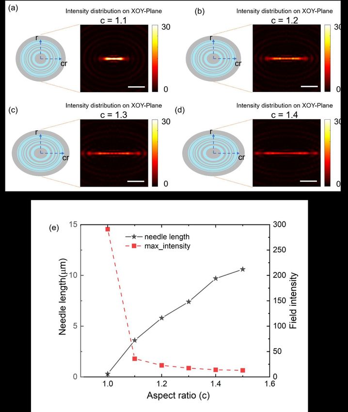
Nanomaterials 2023, 13, 242 7 of 15

 Figure
 Figure 4. Light field 4. Light of
 distribution field
 thedistribution of the SCL.
 modified elliptical modified
 (a,b) elliptical
 SimulatedSCL. (a,b)
 result Simulated
 of the transverseresult of th
 verse optical needle in the XOY plane (a) and the XOZ plane
 optical needle in the XOY plane (a) and the XOZ plane (b) shaped by the modified elliptical SCL; (b) shaped by the modified e
 SCL; (c,d) experimental result of the transverse optical needle in the XOY plane (c) and th
 (c,d) experimental result of the transverse optical needle in the XOY plane (c) and the XOZ plane (d);
 plane (d); (e) intensity profiles of the transverse optical needle in the perpendicular direction
 (e) intensity profiles of the transverse optical needle in the perpendicular direction, which is marked by
 is marked by the white dashed line in Figure 4a,c; (f) axial intensity distribution from the sim
 the white dashed (red
 line in Figure
 line) and4a,c; (f) axial intensity
 the experiment (blue distribution
 dash symbol),from the simulation
 which is marked(red line)
 by the and the
 white dash lines in
 experiment (blue4b,d;dash (g)
 symbol), which is marked by the white dash lines in Figure 4b,d; (g) intensity
 intensity profiles along the transverse optical needle from the simulation (red lin
 profiles along the experimental
 transverse optical needle
 results from
 (blue starthe simulation
 symbol); (redlateral
 (h) the line) and experimental
 sizes results
 in a horizontal (blue which
 direction,
 star symbol); (h) the lateralsub-diffraction-limited
 uniform sizes in a horizontal direction,
 opticalwhich show a uniform sub-diffraction-limited
 needle.
 optical needle.

 Moreover, the uniformity, in the aspects of intensity distribution and lateral size along
 the needle region, is another important feature for the transverse optical needle. Apparently,
 as we can see from Figure 4g, the transverse optical needle could basically keep the field
 intensity in a constant, ranging from −2.0 to 2.0 µm along the needle region. The FWHM
 values in different positions along the optical needle are presented in Figure 4h, which
 clearly shows the uniform sub-diffraction-limited property within the needle region. The
 experimental measured lateral size of the transverse optical needle varies from 0.44λ/NA
 to 0.46λ/NA within the entire optical needle, showing great potential for the line-scanning
 super-resolution imaging application.

 3. Discussion
 Besides the circular and elliptical shape, planar metalens could also be constructed
 in a cylindrical configuration, and a different configuration will give different light field
 modulation capabilities. It has been demonstrated that planar metalens with a cylindrical
 configuration could also create a uniform transverse optical needle in the focal plane with
 subwavelength lateral size [35]. Compared with such type configurations, the transverse
 optical needle created by our modified elliptical supercritical lens has much higher field
 intensity in the needle region. To validate this argument, a comparison experiment was
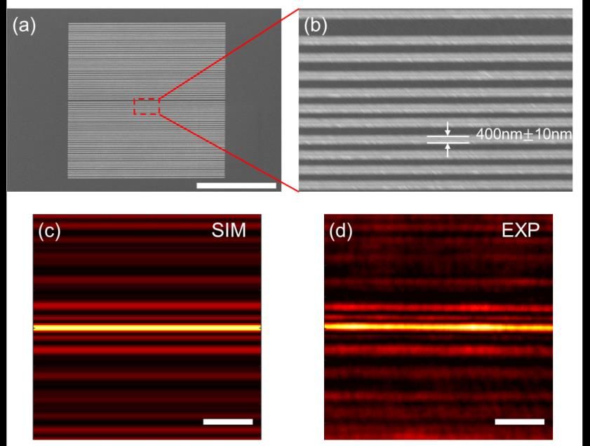
Besides the circular and elliptical shape, planar metalens could also be constructed
 in a cylindrical configuration, and a different configuration will give different light field
 modulation capabilities. It has been demonstrated that planar metalens with a cylindrical
 configuration could also create a uniform transverse optical needle in the focal plane with
 subwavelength lateral size [35]. Compared with such type configurations, the transverse
Nanomaterials 2023, 13, 242 8 of 15
 optical needle created by our modified elliptical supercritical lens has much higher field
 intensity in the needle region. To validate this argument, a comparison experiment was
 performed between our modified elliptical supercritical lens and a grating-type cylindri-
 performed
 cal between
 supercritical lens our
 undermodified
 the sameelliptical supercritical
 optimization lens and
 conditions. a grating-type
 A binary amplitudecylindrical
 cylin-
 supercritical lens under the same optimization conditions. A binary amplitude
 drical supercritical lens with a scale of 100 μm × 100 μm was designed and experimentally cylindrical
 supercritical
 fabricated. Thelens
 SEMwith a scale
 imaging andofits100 µm ×view
 sectional 100 of
 µmthe was designed
 fabricated and experimentally
 cylindrical supercriti-
 fabricated. The SEM imaging and its sectional view of the fabricated cylindrical
 cal lens are shown in Figure A3a,b in Appendix A. As the simulation and experimentally supercritical
 lens are shown
 measured results in Figure
 show A3a,b in
 in Figure Appendix
 A3c,d A. As A,
 in Appendix theasimulation
 transverse and experimentally
 optical needle can
 measured results show in Figure A3c,d in Appendix A, a transverse
 really be obtained in the focal plane when the 633 nm laser beam impinges on the optical needle can
 pattern
 really
 from be obtained
 a He-Ne laser. in thelateral
 The focal size
 plane ofwhen the 633 nm
 the transverse laserconforms
 needle beam impinges on the value,
 to the design pattern
 from a He-Ne laser. The lateral size of the transverse needle conforms to the design
 and the length of the needle region is essentially the same as the scale of the pattern along value,
 and the length of the needle region is essentially the same as the scale of the pattern along
 the horizontal direction, since the diffractive wave has no constriction along the horizontal
 the horizontal direction, since the diffractive wave has no constriction along the horizontal
 direction. By contrast, although our modified elliptical supercritical lens cannot match the
 direction. By contrast, although our modified elliptical supercritical lens cannot match
 cylindrical counterpart in the aspect of the length of the transverse optical needle, our
 the cylindrical counterpart in the aspect of the length of the transverse optical needle, our
 results have significant advantage in terms of the field intensity in the needle region. As
 results have significant advantage in terms of the field intensity in the needle region. As
 schematically presented in Figure 5, the modified elliptical supercritical lens could bundle
 schematically presented in Figure 5, the modified elliptical supercritical lens could bundle
 more light energy into the needle region, and boost the needle intensity much higher. The
 more light energy into the needle region, and boost the needle intensity much higher. The
 field intensity in the needle region of elliptical supercritical lens is 8 times and 7.5 times
 field intensity in the needle region of elliptical supercritical lens is 8 times and 7.5 times
 higher than the cylindrical supercritical lens in the simulation and experimental results,
 higher than the cylindrical supercritical lens in the simulation and experimental results,
 respectively, which makes it more feasible in practical applications.
 respectively, which makes it more feasible in practical applications.

 Figure
 Figure5.5.Comparison
 Comparisonofofthreethreedifferent
 differenttypes
 typesofofsupercritical
 supercriticallens.
 lens.(a)(a)Schematic
 Schematicdiagram
 diagramofofsub-
 sub-
 diffraction-limited
 diffraction-limitedfocusing
 focusingofofdifferent
 differentplanar
 planardiffractive
 diffractivelenses,
 lenses,including
 includinga aconventional
 conventionalcircular
 circular
 supercritical
 supercriticallens,
 lens,a a1D1Dgrating-type
 grating-typecylindrical
 cylindricalsupercritical
 supercriticallens,
 lens,and
 andananelliptical
 ellipticalsupercritical
 supercriticallens;
 lens;
 (b)
 (b) the relative intensity of the focal spot created by the circular SCL and transverseneedles
 the relative intensity of the focal spot created by the circular SCL and transverse needlescreated
 created
 by the cylindrical SCL and elliptical SCL. AU stand for Airy units; that is the radius of the Airy spot
 in the diffraction limited optical system. The transverse optical needle created by the elliptical SCL is
 shorter than the cylindrical SCL, but with eight times higher field intensity in the needle region.

 4. Conclusions
 In summary, we proposed an elliptical supercritical lens which could generate a
 sub-diffraction-limited transverse optical needle in the focal plane. Contrary to the previ-
 ously demonstrated planar metalens with circular symmetry, the demonstrated elliptical
 supercritical lens consists of a series of concentric ellipse configurations. Such a type of
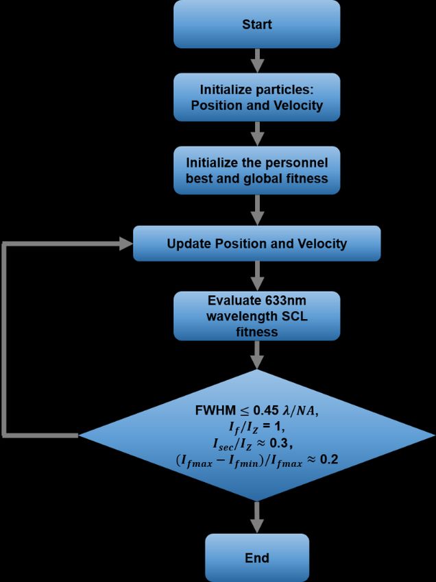
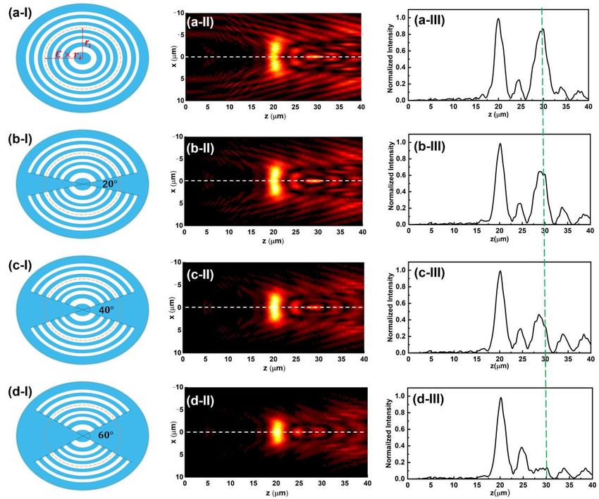
Nanomaterials 2023, 13, 242 9 of 15

 planar metalens was designed by a modified Rayleigh–Sommerfeld diffraction integral
 algorithm in conjunction with the particle swarm optimization technique. The experimental
 demonstrations have verified that a 7λ-long transverse optical needle with lateral size of
 0.46 λ /NA has been obtained in the focal plane 30 µm away from the lens plane. The
 light field distribution of a uniform intensity in the transverse optical needle region has
 shown significant advantage in the aspect of field intensity compared with the cylindrical
 sub-diffraction-limited planar metalens under the same conditions. The abovementioned
 unique property means our elliptical SCL has important value in the application of line-
 scanning super-resolution confocal microscopy. In addition, it can also serve as an ideal
 way in future applications, such as in ultra-precision optical micro-manipulation, optical
 data storage, etc.

 Author Contributions: Conceptualization, J.L. and F.Q.; methodology, J.L. and M.W.; software, J.L.
 and J.W.; validation, J.L., J.W., and F.Q.; formal analysis, J.L., M.W., and F.Q.; investigation, J.L., M.W.,
 and K.Z.; resources, K.Z. and S.W.; data curation, J.L., J.W., H.D., M.W., and S.W.; writing—original
 draft preparation, J.L., J.W., H.D., M.W., and S.W.; writing—review and editing, J.L., S.W., Y.C., F.Q.,
 and X.L.; visualization, J.L. and M.W.; supervision, F.Q. and X.L.; project administration, F.Q.; funding
 acquisition, F.Q. All authors have read and agreed to the published version of the manuscript.
 Funding: This research was funded by the National Natural Science Foundation of China (NSFC) (Grant
 Nos. 62075085, 61975066, 61875073), National Key R&D Program of China (2021YFB2802003), Guang-
 dong Basic and Applied Basic Research Foundation (Grant No. 2020B1515020058, 2019A1515010864,
 2021A1515011586), and Guangzhou Science and Technology Program (Grant no. 202002030258).
 Institutional Review Board Statement: Ethical review and approval were waived for this study due
 to not applicable.
 Informed Consent Statement: Patient consent was waived due to not applicable.
 Data Availability Statement: The data presented in this study are available on request from the
 corresponding author.
 Conflicts of Interest: The authors declare no conflict of interest.

 Appendix A
 Appendix A.1. Design of Binary Amplitude Elliptical Super-Critical Lens
 By using the modified RS diffraction integral method, a binary amplitude-type ellip-
 tical supercritical lens was designed. The optimization algorithm we used is the particle
 swarm optimization algorithm (PSO). The length of the semi-minor axis of the outermost
 elliptical belt is ~50 µm, and the numerical aperture is set at NA = 0.85. The minimum belt
 width is set at 400 nm to facilitate the nanofabrication process. Regarding the transverse
 optical needle preparing for the application in line-scanning super-resolution imaging,
 there are three important characteristics that need to be met simultaneously: sub-diffraction-
 limited lateral size, uniform field distribution, and lower subsidiary focusing effect around
 the needle region. All those features need to be considered during the optimization proce-
 dure. The optimization procedure for designing elliptical SCL is shown in Figure A1.
 It is noted that the ellipticity factor is the essential parameter distinguishing an ellipse
 from a circle. The length of the created transverse optical needle by the elliptical supercriti-
 cal lens heavily relies on the ellipticity of the structures. As the simulation results show
 in Figure A2, the property of the transverse optical needle will be changed along with the
 ellipticity factor alteration. Larger ellipticity will give a longer transverse optical needle,
 but lower intensity in the needle region. A proper elliptical factor should be selected in the
 lens design.
 The optimization process can be divided into two steps as follows: (I) generate the
 position and the width data of a set of belt positions randomly by using the particle swarm
 optimization algorithm, and then use a set of parameters to form the corresponding binary
 amplitude elliptical supercritical lens at a wavelength of 633 nm for evaluating the focused
 performance. Different from the supercritical lens in the circular configuration, the elliptical
with the ellipticity factor alteration. Larger ellipticity will give a longer transverse optical
 needle, but lower intensity in the needle region. A proper elliptical factor should be se-
 lected in the lens design.
 The optimization process can be divided into two steps as follows: (Ⅰ) generate the
 position and the width data of a set of belt positions randomly by using the particle swarm
Nanomaterials 2023, 13, 242 optimization algorithm, and then use a set of parameters to form the corresponding10 of 15
 binary
 amplitude elliptical supercritical lens at a wavelength of 633 nm for evaluating the focused
 performance. Different from the supercritical lens in the circular configuration, the ellip-
 tical structure
 structure can makecan themake the focused
 focused light
 light field field along
 spread spreadx along
 axis, sox we
 axis, so we calculate
 calculate the
 the integral
 ofintegral offield
 the light the light field(Iintensity
 intensity Z ) of each(I Z) of on
 point eachthepoint onaxis
 optical thewithin
 opticala axis within
 certain a certain
 length along
 length
 the along
 x-axis; (II)the x-axis; (II)
 compare the compare the value
 value obtained obtained
 from from the evaluation
 the evaluation function withfunction with
 the final
 value. If the
 the final precision
 value. If the of the target
 precision of value is reached,
 the target value isthe optimization
 reached, is completed,
 the optimization and
 is com-
 the optimized
 pleted, and theparameters
 optimized are output. are
 parameters Otherwise, it will enteritthe
 output. Otherwise, willnext generation
 enter until
 the next gener-
 the precision of the target value is reached. The optimized parameters
 ation until the precision of the target value is reached. The optimized parameters of the of the elliptical
 supercritical lens are shown
 elliptical supercritical in Table
 lens are shown A1.
 in Table A1.

 FigureA1.
 Figure A1.The
 Theoptimization
 optimizationprocedure
 procedurefor
 forshaping
 shapingsub-diffraction-limited
 sub-diffraction-limitedtransverse
 transverseoptical
 opticalneedle
 needle
 by an elliptical SCL.
 by an elliptical SCL.

 Table A1. The position information of each belt for elliptical supercritical lens.

 Opaque Transparent Opaque Transparent
 No 0 1 No 0 1
 Rin/µm Rout/µm Rin/µm Rout/µm Rin/µm Rout/µm Rin/µm Rout/µm
 1 0.00 4.37 4.37 6.20 21 29.38 30.17 30.17 30.57
 2 6.20 7.61 7.61 8.81 22 30.57 31.28 31.28 31.68
 3 8.81 9.87 9.87 10.84 23 31.68 32.43 32.43 32.83
 4 10.84 11.74 11.74 12.58 24 32.83 33.33 33.33 33.73
 5 12.58 13.38 13.38 14.14 25 33.73 34.20 34.20 34.60
 6 14.14 14.57 14.57 14.97 26 34.60 35.09 35.09 35.49
 7 14.97 15.58 15.58 15.98 27 35.49 35.99 35.99 36.39
 8 15.98 16.46 16.46 16.86 28 36.39 37.00 37.00 37.40
 9 16.86 17.72 17.72 18.12 29 37.40 38.14 38.14 38.54
 10 18.12 18.76 18.76 19.16 30 38.54 39.04 39.04 39.44
Nanomaterials 2023, 13, 242 11 of 15

 Table A1. Cont.

 Opaque Transparent Opaque Transparent
 No 0 1 No 0 1
 Rin/µm Rout/µm Rin/µm Rout/µm Rin/µm Rout/µm Rin/µm Rout/µm
 11 19.16 20.00 20.00 20.40 31 39.44 40.01 40.01 40.41
 12 20.40 20.93 20.93 21.33 32 40.41 40.93 40.93 41.33
 13 21.33 22.16 22.16 22.56 33 41.33 42.22 42.22 42.62
 14 22.56 23.16 23.16 23.56 34 42.62 43.07 43.07 43.47
 15 23.56 24.34 24.34 24.74 35 43.47 44.16 44.16 44.56
 16 24.74 25.14 25.14 25.54 36 44.56 45.08 45.08 45.48
 17 25.54 26.13 26.13 26.53 37 45.48 46.11 46.11 46.51
 18 26.53 27.17 27.17 27.57 38 46.51 47.00 47.00 47.40
 19 27.57 28.07 28.07 28.47 39 47.40 47.99 47.99 48.39
 Nanomaterials 2023, 13, x FOR PEER REVIEW 11 of 15
 20 28.47 28.98 28.98 29.38 40 48.39 49.04 49.04 49.44

 Figure A2. The scheme and intensity distribution of the transverse optical needle shaping by elliptical
 Figure A2. The scheme and intensity distribution of the transverse optical needle shaping by ellip-
 SCLSCL
 tical with different
 with aspect
 different aspectratios
 ratios(a–d).
 (a–d). Scalebar: 350nm.
 Scalebar: 350 nm.ItItcan
 canbebeseen
 seen from
 from thethe statistic
 statistic chart (e) that
 chart
 asthat
 (e) the as
 aspect ratio cratio
 the aspect increases from from
 c increases 1.0 to1.0
 1.4,tothe
 1.4,length of theoftransverse
 the length the transverseneedle willwill
 needle be increased,
 be but
 the lightbut
 increased, field
 theintensity
 light fieldin the needle
 intensity in theregion
 needle will
 region bewill
 dropped. To reach
 be dropped. a compromise
 To reach a compromise between the
 between the length
 length and and of
 intensity intensity of theneedle,
 the optical optical needle, the aspect
 the aspect ratio value
 ratio value of 1.2ofis1.2 is chosen
 chosen in our
 in our design.
 design.

 Table A1. The position information of each belt for elliptical supercritical lens

 Opaque Transparent Opaque Transparent
 No 0 1 No 0 1
 Rin/μm Rout/μm Rin/μm Rout/μm Rin/μm Rout/μm Rin/μm Rout/μm
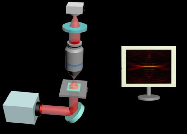
Nanomaterials 2023, 13, 242 12 of 15

 Appendix A.2. Introduction of the Sector-Shape Cutting Region
 From the geometric perspective, the major difference between the circle and ellipse
 is that the ellipse shape has angle-dependent variable radial length. The same spatial
 frequency light diffracted from the minor axis direction and major axis direction will
 converged on different z positions. Thus, affected by this distinguished configuration
 of the elliptical belts, intricate field intensity distribution will be created in the far field
 when an ellipse shape is used to construct a diffractive lens. Besides the transverse optical
 needle in the designed focal plane, a series of subsidiary intensity peaks appeared in the
 focal region, as shown in Figure 2aI–aIII. To allow this phenomenon to obtain a uniform
 transverse optical needle, the elliptical structure morphology needs to be modified. As
 schematically shown in Figure 2bI–bIII,dI–dIII, a pair of sector-shape cutting regions were
 introduced. In the theoretical attempt, a sector shape with a different angle from 0 deg to
 60 deg was simulated. It was found that the sector shape with 60 deg will give a better
 performance, where the subsidiary focused light field generated by the original ellipse
 structure will be effectively suppressed. In addition, the modified elliptical supercritical
 lens also shows additional benefits in the aspect of uniformity of the transverse optical
 needle. The diffraction field of the modified elliptical supercritical lens can be calculated
 with the Equation (A1) as follow:
 Z r 5π
 1 iknR − 1
 Z
 θ_out 6
 U (ρ, θ, z) = − U0 (rθ , θ ) exp(iknR) × × zrθ drθ dθ, (A1)
 π rθ_in π
 6
 R3

 Appendix A.3. Nanofabrication Process of the Binary Amplitude Supercritical Lens
 The elliptical supercritical lens with binary amplitude configuration was fabricated
 by using electron-beam lithography, followed by a standard e-beam deposition and lift-off
 process, as shown in Figure 3. The structure was patterned on a 1mm-thick ITO substrate.
 After thoroughly cleaning the substrate with acetone, isopropyl alcohol (IPA), and deionized
 (DI) water, the positive electron beam resist PMMA A4 (MicroChem, Cook County, GA,
 USA) was spin coated at 2000 rpm on the prepared substrate with a thickness of 300 nm, and
 then baked on a hot plate for 3 min at 180 ◦ C. The EBL system (EBPG5150, Raith, Best, The
 Netherlands) had an acceleration voltage of 100 keV and a dose of 510 µC/cm2 . Since the
 smallest feature size of our pattern is 400 nm, proximity effect correction is unnecessary in
 the lithography process. After the developing process, a 100 nm-thick titanium (Ti) film was
 deposited on the sample by electron-beam evaporator (Explorer Coating System, Denton
 Vacuum, Moorestown, NJ, USA) with a deposition velocity of 0.1 nm/s. Subsequently, the
 sample was soaked in the stripping solution overnight for lift-off process, then the final
 sample was obtained. The fabricated elliptical supercritical lens was imaged by using a
 scanning electron microscope (Apreo HiVac, FEI, Hillsboro, OR, USA) with an accelerating
 voltage of 5 kV. As a control sample, a cylindrical supercritical lens with a similar size has
 been fabricated with the same procedure, as shown in Figure A3.

 Appendix A.4. Optical Characterization of the Patterned Supercritical Lenses
 The optical characterization of the elliptical supercritical lens was performed by a
 self-built microscope, as schematically shown in Figure A4. A low power He-Ne linear
 polarized laser (DH-HN250P, 2 mW, Daheng Optics, Beijing, China) was applied as the
 illumination source. The wavelength is 633 nm, and the polarization state is in the x
 direction along the major axis of the ellipse. In experiments, the laser beam was illuminated
 on the binary amplitude type elliptical supercritical lens from the substrate side. The
 alignment between the laser beam and the SCL was performed by a motorized translation
 stage (PI, M687PILine, Karlsruhe, Germany). An objective lens with NA = 0.9 (Nikon, TU
 plan EPI 100X, Tokyo, Japan) was used to collect the transmitted light. The image of the
 transmitted light field was acquired and recorded by a high quantum efficiency CMOS
 camera (Nikon Qi2, Tokyo, Japan) in order to obtain the field intensity in the xy plane. A
 2.5X extender tube is inserted in between the objective lens and CMOS camera to further
Nanomaterials 2023, 13, 242 13 of 15

 increase the magnification. The intensity distribution in the XOZ plane was obtained
 by scanning the SCL along the z direction by a Piezo stage (PI, P-736.ZRN, Karlsruhe,
Nanomaterials 2023, 13, x FOR PEER REVIEW 13 of 15
 Germany) with a stepwise of 200 nm, and then mapping the intensity distribution in the
 longitudinal plane.

 Figure A3. (a,b) The SEM image and its sectional zoom-in view of the grating-type cylindrical su-
 percritical lens, scalebar: 50 μm; (c,d) the field intensity distribution in the XOY plane of the trans-
 verse optical needle created by the grating-type cylindrical SCL for the simulated result (c) and the
 experimental result (d), scalebar: 3 μm.

 Appendix A.4. Optical Characterization of the Patterned Supercritical Lenses
 The optical characterization of the elliptical supercritical lens was performed by a
 self-built microscope, as schematically shown in Figure A4. A low power He-Ne linear
 polarized laser (DH-HN250P, 2 mW, Daheng Optics, Beijing, China) was applied as the
 illumination source. The wavelength is 633 nm, and the polarization state is in the x direc-
 tion along the major axis of the ellipse. In experiments, the laser beam was illuminated on
 the binary amplitude type elliptical supercritical lens from the substrate side. The align-
 ment between the laser beam and the SCL was performed by a motorized translation stage
 (PI, M687PILine, Karlsruhe, Germany). An objective lens with NA = 0.9 (Nikon, TU plan
 EPI 100X, Tokyo, Japan) was used to collect the transmitted light. The image of the trans-
 mitted light field was acquired and recorded by a high quantum efficiency CMOS camera
 (Nikon Qi2, Tokyo, Japan) in order to obtain the field intensity in the xy plane. A 2.5X
 extender tube is inserted in between the objective lens and CMOS camera to further in-
 (a,b)The
 TheSEMSEMimage
 imageand anditsits sectional zoom-in
 Figure A3.
 crease A3.
 the(a,b)
 magnification. The intensitysectional zoom-in
 distribution in view
 viewthe of the
 of XOZ
 the grating-type
 grating-type
 plane cylindrical
 wascylindrical
 obtained su-
 by
 percritical lens,
 supercritical scalebar:
 lens, 50 μm;
 scalebar: (c,d)(c,d)
 50 µm; the field intensity
 the field distribution
 intensity in theinXOY
 distribution the plane of the of
 XOY plane trans-
 the
 scanning the SCL along the z direction by a Piezo stage (PI, P-736.ZRN, Karlsruhe, Ger-
 verse optical
 transverse needle
 optical created
 needle by the grating-type
 created cylindrical SCL SCL
 for the
 forsimulated result (c) and the
 many) with a stepwise of 200 bynm,the grating-type
 and then mapping cylindrical
 the intensity the simulated
 distributionresult (c) and
 in the lon-
 experimental result (d), scalebar: 3 μm.
 the experimental result (d), scalebar: 3 µm.
 gitudinal plane.
 Appendix A.4. Optical Characterization of the Patterned Supercritical Lenses
 The optical characterization of the elliptical supercritical lens was performed by a
 self-built microscope, as schematically shown in Figure A4. A low power He-Ne linear
 polarized laser (DH-HN250P, 2 mW, Daheng Optics, Beijing, China) was applied as the
 illumination source. The wavelength is 633 nm, and the polarization state is in the x direc-
 tion along the major axis of the ellipse. In experiments, the laser beam was illuminated on
 the binary amplitude type elliptical supercritical lens from the substrate side. The align-
 ment between the laser beam and the SCL was performed by a motorized translation stage
 (PI, M687PILine, Karlsruhe, Germany). An objective lens with NA = 0.9 (Nikon, TU plan
 EPI 100X, Tokyo, Japan) was used to collect the transmitted light. The image of the trans-
 mitted light field was acquired and recorded by a high quantum efficiency CMOS camera
 (Nikon Qi2, Tokyo, Japan) in order to obtain the field intensity in the xy plane. A 2.5X
 extender tube is inserted in between the objective lens and CMOS camera to further in-
 Figure A4.
 Figure A4. Schematic
 Schematic illustration
 illustration of
 of the
 the optical
 optical characterization
 characterization system.
 system.
 crease the magnification. The intensity distribution in the XOZ plane was obtained by
 scanning the SCL along the z direction by a Piezo stage (PI, P-736.ZRN, Karlsruhe, Ger-
References many) with a stepwise of 200 nm, and then mapping the intensity distribution in the lon-
1. Gareau, D.S.; Krueger, J.G.; Hawkes,
 gitudinalJ.E.; Lish, S.R.; Dietz, M.P.; Mulberger, A.G.; Mu, E.W.; Stevenson, M.L.; Lewin, J.M.; Meehan,
 plane.
 S.A.; et al. Line scanning, stage scanning confocal microscope (LSSSCM). Biomed. Opt. Express 2017, 8, 3807–3815. [CrossRef]
2. Tsang, J.M.; Gritton, H.J.; Das, S.L.; Weber, T.D.; Chen, C.S.; Han, X.; Mertz, J. Fast, multiplane line-scan confocal microscopy
 using axially distributed slits. Biomed. Opt. Express 2021, 12, 1339–1350. [CrossRef]
3. Mei, E.; Fomitchov, P.A.; Graves, R.; Campion, M. A line scanning confocal fluorescent microscope using a CMOS rolling shutter
 as an adjustable aperture. J. Microsc. 2012, 247, 269–276. [CrossRef]
4. Im, K.-B.; Han, S.; Park, H.; Kim, D.; Kim, B.-M. Simple high-speed confocal line-scanning microscope. Opt. Express 2005, 13,
 5151–5156. [CrossRef]
Nanomaterials 2023, 13, 242 14 of 15

5. Zhang, P.; Phipps, M.E.; Goodwin, P.M.; Werner, J.H. Light-sheet microscopy by confocal line scanning of dual-Bessel beams. J.
 Biomed. Opt. 2016, 21, 100502. [CrossRef]
6. Zhong, Q.; Li, A.; Jin, R.; Zhang, D.; Li, X.; Jia, X.; Ding, Z.; Luo, P.; Zhou, C.; Jiang, C.; et al. High-definition imaging using
 line-illumination modulation microscopy. Nat. Methods 2021, 18, 309–315. [CrossRef]
7. Yuan, G.; Rogers, E.T.; Zheludev, N.I. Achromatic super-oscillatory lenses with sub-wavelength focusing. Light Sci. Appl. 2017, 6,
 e17036. [CrossRef] [PubMed]
8. Yuan, G.; Rogers, E.T.; Roy, T.; Adamo, G.; Shen, Z.; Zheludev, N.I. Planar super-oscillatory lens for sub-diffraction optical needles
 at violet wavelengths. Sci. Rep. 2014, 4, 6333. [CrossRef] [PubMed]
9. Tang, D.; Wang, C.; Zhao, Z.; Wang, Y.; Pu, M.; Li, X.; Gao, P.; Luo, X. Ultrabroadband superoscillatory lens composed by
 plasmonic metasurfaces for subdiffraction light focusing. Laser Photon. Rev. 2015, 9, 713–719. [CrossRef]
10. Qin, F.; Huang, K.; Wu, J.; Jiao, J.; Luo, X.; Qiu, C.; Hong, M. Shaping a subwavelength needle with ultra-long focal length by
 focusing azimuthally polarized light. Sci. Rep. 2015, 5, 9977. [CrossRef]
11. Qin, F.; Liu, B.; Zhu, L.; Lei, J.; Fang, W.; Hu, D.; Zhu, Y.; Ma, W.; Wang, B.; Shi, T.; et al. pi-phase modulated monolayer
 supercritical lens. Nat. Commun. 2021, 12, 32. [CrossRef] [PubMed]
12. Fang, W.; Lei, J.; Zhang, P.; Qin, F.; Jiang, M.; Zhu, X.; Hu, D.; Cao, Y.; Li, X. Multilevel phase supercritical lens fabricated by
 synergistic optical lithography. Nanophotonics 2020, 9, 1469–1477. [CrossRef]
13. Zhu, X.; Fang, W.; Lei, J.; Li, Z.; Xie, F.; Cao, Y.; Zhang, Y.; Qin, F.; Li, X. Supercritical lens array in a centimeter scale patterned
 with maskless UV lithography. Opt. Lett. 2020, 45, 1798–1801. [CrossRef] [PubMed]
14. Wang, C.; Tang, D.; Wang, Y.; Zhao, Z.; Wang, J.; Pu, M.; Zhang, Y.; Yan, W.; Gao, P.; Luo, X. Super-resolution optical telescopes
 with local light diffraction shrinkage. Sci. Rep. 2015, 5, 18485. [CrossRef]
15. Yuan, G.; Zheludev, N.I. Detecting nanometric displacements with optical ruler metrology. Science 2019, 364, 771–775. [CrossRef]
16. Qin, F.; Huang, K.; Wu, J.; Teng, J.; Qiu, C.W.; Hong, M. A Supercritical Lens Optical Label-Free Microscopy: Sub-Diffraction
 Resolution and Ultra-Long Working Distance. Adv. Mater. 2017, 29, 1602721. [CrossRef]
17. Rogers, E.T.F.; Quraishe, S.; Rogers, K.S.; Newman, T.A.; Smith, P.J.S.; Zheludev, N.I. Far-field unlabeled super-resolution imaging
 with superoscillatory illumination. APL Photonics 2020, 5, 066107. [CrossRef]
18. Rogers, E.T.; Lindberg, J.; Roy, T.; Savo, S.; Chad, J.E.; Dennis, M.R.; Zheludev, N.I. A super-oscillatory lens optical microscope for
 subwavelength imaging. Nat. Mater. 2012, 11, 432–435. [CrossRef]
19. Klar, T.A.; Jakobs, S.; Dyba, M.; Egner, A.; Hell, S.W. Fluorescence microscopy with diffraction resolution barrier broken by
 stimulated emission. Proc. Natl. Acad. Sci. USA 2000, 97, 8206–8210. [CrossRef]
20. Westphal, V.; Rizzoli, S.O.; Lauterbach, M.A.; Kamin, D.; Jahn, R.; Hell, S.W. Video-rate far-field optical nanoscopy dissects
 synaptic vesicle movement. Science 2008, 320, 246–249. [CrossRef]
21. Denk, W.; Strickler, J.; Webb, W. Two-photon laser scanning fluorescence microscopy. Science 1990, 248, 73–76. [CrossRef]
22. Gissibl, T.; Thiele, S.; Herkommer, A.; Giessen, H. Two-photon direct laser writing of ultracompact multi-lens objectives. Nat.
 Photonics 2016, 10, 554–560. [CrossRef]
23. Wang, J.; Qin, F.; Zhang, D.; Li, D.; Wang, Y.; Shen, X.; Yu, T.; Teng, J. Subwavelength superfocusing with a dipole-wave-reciprocal
 binary zone plate. Appl. Phys. Lett. 2013, 102, 061103. [CrossRef]
24. Zheng, X.; Jia, B.; Lin, H.; Qiu, L.; Li, D.; Gu, M. Highly efficient and ultra-broadband graphene oxide ultrathin lenses with
 three-dimensional subwavelength focusing. Nat. Commun. 2015, 6, 8433. [CrossRef]
25. Wang, H.; Shi, L.; Lukyanchuk, B.; Sheppard, C.; Chong, C.T. Creation of a needle of longitudinally polarized light in vacuum
 using binary optics. Nat. Photonics 2008, 2, 501–505. [CrossRef]
26. Wang, H.; Hao, C.; Lin, H.; Wang, Y.; Lan, T.; Qiu, C.; Jia, B. Generation of super-resolved optical needle and multifocal array
 using graphene oxide metalenses. Opto-Electron. Adv. 2021, 4, 20003101–20003115. [CrossRef]
27. Dai, X.; Dong, F.; Zhang, K.; Liao, D.; Li, S.; Shang, Z.; Zhou, Y.; Liang, G.; Zhang, Z.; Wen, Z.; et al. Holographic Super-Resolution
 Metalens for Achromatic Sub-Wavelength Focusing. ACS Photonics 2021, 8, 2294–2303. [CrossRef]
28. Kim, J.; Seong, J.; Yang, Y.; Moon, S.-W.; Badloe, T.; Rho, J. Tunable metasurfaces towards versatile metalenses and metaholograms:
 A review. Adv. Photonics 2022, 4, 024001. [CrossRef]
29. Yoon, G.; Kim, K.; Huh, D.; Lee, H.; Rho, J. Single-step manufacturing of hierarchical dielectric metalens in the visible. Nat.
 Commun. 2020, 11, 2268. [CrossRef]
30. Yoon, G.; Jang, J.; Mun, J.; Nam, K.T.; Rho, J. Metasurface zone plate for light manipulation in vectorial regime. Comms. Phys.
 2019, 2, 156. [CrossRef]
31. Huang, K.; Liu, H.; Garcia-Vidal, F.J.; Hong, M.; Luk’yanchuk, B.; Teng, J.; Qiu, C.W. Ultrahigh-capacity non-periodic photon
 sieves operating in visible light. Nat. Commun. 2015, 6, 7059. [CrossRef] [PubMed]
32. Huang, K.; Qin, F.; Liu, H.; Ye, H.; Qiu, C.; Hong, M.; Yanchuk, B.L.; Teng, J. Planar Diffractive Lenses: Fundamentals,
 Functionalities, and Applications. Adv. Mater. 2018, 30, 1704556. [CrossRef]
33. Jin, Z.; Janoschka, D.; Deng, J.; Ge, L.; Dreher, P.; Frank, B.; Hu, G.; Ni, J.; Yang, Y.; Li, J.; et al. Phyllotaxis-inspired nanosieves
 with multiplexed orbital angular momentum. eLight 2021, 1, 5. [CrossRef]
You can also read