Dicktator Engine Management System - Accuracy you can depend on - Instruction Manual for
←
→
Page content transcription
If your browser does not render page correctly, please read the page content below
Dicktator
   Engine Management System
Instruction Manual for:
                          Dicktator Std
                          Dicktator Wasted Spark
                          Dicktator 60-2 & 36-1

   Accuracy you can depend on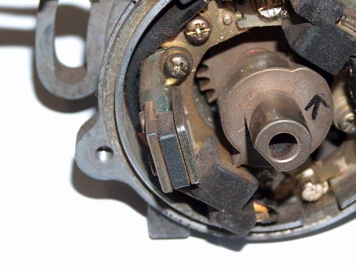
Contents

1. Installation Guide ..................................... 4
 •       Computer Requirements ....................................................... 4
 •       Installing the Dicktator Software............................................ 4
 •       Finding the icon to start the Dicktator software ..................... 8
 •       How to connect the Dicktator to the PC software.................. 8
2. Using the PC Software ............................. 9
 •       Initial Setup of the ECU ......................................................... 9
     -     Number of Cylinders: .........................................................................9
     -     Ignition Divide by: ............................................................................10
     -     Rev Limiter: .....................................................................................10
     -     Rev Limiter Type: ............................................................................10
     -     Startup Prime:..................................................................................10
     -     Installed MAP Sensor: .....................................................................10
     -     MAP Sensor Range Scaling: ...........................................................11
     -     MAP Based or Throttle Based: ........................................................11
     -     Enable Altitude Compensation: .......................................................11
     -     Spark Mode: ....................................................................................12
     -     Dwell Control: ..................................................................................12
     -     Duty Percentage/Charge Time: .......................................................12
     -     Trigger Angle: ..................................................................................12
     -     Pot/Auxiliary Input Setup: ................................................................13
     -     Fuel Pump Priming: .........................................................................13
     -     RPM Sites Spacing:.........................................................................13
     -     Fuel Load Sites Setup: ....................................................................14
 •       Calibrating the Sensors....................................................... 15
     -     Throttle Position Sensor: .................................................................15
     -     Water Temperature Sensor: ............................................................16
     -     Air Temperature Sensor: .................................................................16
 •       Setting up the Trigger Edges .............................................. 17
     -     Input Trigger Edge:..........................................................................17
     -     Home Position Edge: .......................................................................17
     -     Spark Trigger Edge: ........................................................................17
 •       Setting the optional outputs................................................. 18
     -     Flap/VTEC/NOS/Shift Light/RPM Switch .........................................18
     -     Launch and Anti Lag Control Setup .................................................19
     -     Idle Control Setup............................................................................20
     -     How to up set the Idle Control .........................................................21
 •       Working with Compensation Maps...................................... 22
     -     Battery Voltage: ...............................................................................22
     -     Water Temperature Compensation: ................................................22
     -     Air Temperature Compensation:......................................................23
     -     Throttle Pump Compensation: .........................................................23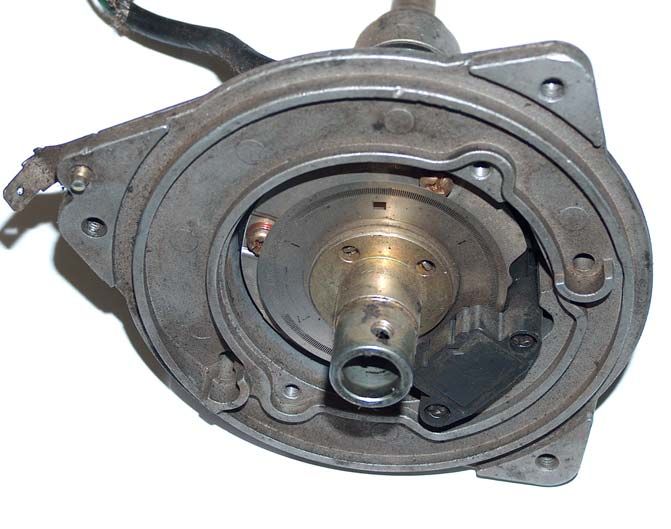
•       Working with the Fuel Maps ................................................ 25
     -     How to Navigate through the Map: ..................................................26
     -     How to Tune or Change the Fuel Values in the Map: ......................26
     -     Using the All Ranges Up Function:..................................................27
 •       Working with the Ignition Maps ........................................... 28
     -     How to Navigate through the Map: ..................................................29
     -     How to Tune or Change the Fuel Values in the Map: ......................29
     -     Using the All Ranges Left Function: ................................................30
3. How to Tune ............................................ 31
 •       What are the Crosshairs used for?...................................... 31
 •       What is Interpolation? ......................................................... 31
 •       What Keys are used? .......................................................... 32
 •       Tuning the Fuel Maps ......................................................... 32
 •       Tuning for Fuel Economy .................................................... 33
 •       Tuning for Power................................................................. 33
 •       Tuning the Ignition Maps ..................................................... 33
 •       What is Detonation .............................................................. 34
4. What Dicktator to use............................. 35
5. Wiring up the System............................. 36
 •       Where to start...................................................................... 36
 •       Tools you will need.............................................................. 36
 •       What potential problems to look out for............................... 36
     -     Engine earth ....................................................................................36
     -     Spark Plugs .....................................................................................37
     -     Throttle Position Sensors (TPS) ......................................................38
     -     What type of pick-up do I need? ......................................................41
     -     What type of pick-up do I have? ......................................................44
     -     Do I need a magnetic converter?.....................................................48
     -     Fuel pumps......................................................................................49
     -     Where to Dyno?...............................................................................50
 •       Connecting up the ECU ...................................................... 51
 •       ECU Plug pin functions and wire colours diagram .............. 53
 •       What igniters to use ............................................................ 54
     -     Processor Controlled Ignitions (Smart Igniters) ...............................54
     -     Dumb Igniters ..................................................................................54
     -     Preferred Igniters.............................................................................54
     -     Dicktator’s Single, Twin, Triple and Quad Igniters ...........................54
     -     No Igniter Required .........................................................................55
6. Glossary .................................................. 56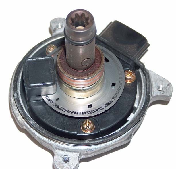
1. Installation Guide

• Computer Requirements

The programming software requires a PC running Windows
XP, Windows Millennium, Windows 2000, Windows 98 or
Windows 95 release 2 along with the following specifications.

Minimum Requirements:

     133MHz processor
     16Mb of RAM memory
     20 MB of free Disk space
     VGA colour display 800x600 (preferably 1024x768)

Recommended:

     400MHz processor
     64Mb of RAM memory
     100 MB of free disk space
     VGA colour display 1024x768

• Installing the Dicktator Software

Installing the Dicktator software onto your PC is performed
similar to any other Windows software package. These basic
steps below should ensure correct installation of the software:

1.    Insert the CD-ROM disk into your PC’s CD-ROM drive.
2.    Run the executable file “SETUP.EXE” from the CD-ROM
drive.
3. The installation program will startup with a welcome
screen. Click on OK to continue.

4. On the Begin Installation Screen there is a big square
button to start the process. Typically you should just press the
button to continue. Otherwise, if you wish you can install the
software into a specific folder on your hard drive. Click the Big
square button to start the installation.
5. With the icon screen you have the opportunity to place
the icon in a specific place on the start menu. Typically you
just press Continue and allow the software to place the icon
automatically.

6. The progress screen is just an informative screen to
show you that the computer has not gotten stuck in a process.
Do not do anything with this screen.
7. This is the File Version Conflict Screen. This screen will
only pop up if you already have a version of Dicktator on you
computer. If it does, then exit the installation and remove the
previous version of Dicktator software through the control
panel.

8. Once the Installation has completed its task, the setup
completion screen will appear. Just click OK and the
installation is final.
• Finding the icon to start the Dicktator software
1. Click on the Start button.
2. Click on programs.
3. Click on the Dicktator folder.
4. Click on the Dicktator Icon

• How to connect the Dicktator to the PC software

All you need is a standard RS232 serial comms cable. If you
don’t have a cable and want to make one, its still a simple job.
You need a male and female 9 pin connector. Get a 3 core
wire and connect pins 2-2, 3-3, 5-5 like in the diagram below.

                1                            1
            9                                    9
                2                            2
            8                                    8
                3                            3
            7                                    7
                4                            4
            6                                    6
                5                            5

Once you have your cable, plug it in to the PC and Dicktator.
Turn on your ignition and start the PC software. You will
notice that on the Data Display Page is a bold red bar that will
change to green as soon as there is a connection.

Once the bar goes green, you are connected.
2. Using the PC Software • Initial Setup of the ECU Start up the Dicktator software, connect it to the ECU and turn the ignition on. Now press “M” to go to the Main Setup page. Here you tell the ECU the important settings it needs to work with your type of engine. Here is a description of all the settings. - Number of Cylinders: This is quite self-explanatory. Select the number of cylinders your motor has to get the correct RPM reading. If you are using coil negative as a trigger on a wasted spark system then you will need to half the number of cylinders to correct the RPM reading.
- Ignition Divide by:

This number tells the ECU to fire the injectors every “number”
of pulses. This is typically half the number of cylinders.

- Rev Limiter:

You can move the rev limiter to the desired RPM value in 100
RPM steps. If the motor exceeds this RPM the ECU will cut
the output to what is selected in rev limiter type.

- Rev Limiter Type:

You have a choice between cutting fuel and spark as a rev
limiter. It is advisable to cut spark as it provides a more
positive and softer rev limiter. If you are using coil negative as
a trigger then you will need to cut fuel as spark will not be
controlled by the ECU.

- Startup Prime:

This value tells the ECU how much extra fuel to give at the
initial 3 pulses of the injectors. The motor needs extra fuel to
help quicken starting time. Typical values are from 2.5 ms to
5 ms.

- Installed MAP Sensor:

Default here is 3 bar

This setting tells the ECU what MAP sensor you have
installed in the ECU. This is easy to check. Turn the ignition
on but don’t start the motor. If the correct MAP sensor is
selected then the Boost reading on the Data Display Page will
read between –0.04 and 0.04 at the coast and between –0.22
and –0.10 at altitude. If the reading is not in these ranges then
keep selecting a different MAP sensor until it is.
- MAP Sensor Range Scaling:

This allows you to set the boost range of the map so you are
able to tune using all your map load sites. For example, most
ECU’s will be sent out with 3 Bar MAP sensors but you only
want to boost 1 bar. This would mean that you can only tune
using the first 65% of the map. Now with this function you can
scale the MAP sensor down to simulate, for example, a 2 bar
MAP sensor without having to replace anything.

Never select a range that is lower than the maximum boost
you are going to run. Never allow the Boost value on the Data
Display Page to read OVER. That means the ECU will not
supply the correct fuel and timing at those points.

- MAP Based or Throttle Based:

You can select if the ECU must use the MAP sensor for your
primary load sensing or the Throttle Position Sensor (TPS).
On Turbocharged cars you must use MAP based, and on
normally aspirated cars it is preferable to use TPS Based. It is
more time consuming to tune a TPS Based car, but the fuel
economy gain on a car, with big cams for example, would be
worth it. In Throttle based mode the vacuum pipe must be
disconnected from the motor and left open to atmosphere.

- Enable Altitude Compensation:

This option will only appear if the “Map Based or Throttle
Based” setting has been set to Throttle Based. In Throttle
based mode, the ECU will not compensate for altitude
changes unless this setting is enabled and the vacuum pipe
coming out of the ECU is open to atmosphere. Please make
sure that the vacuum pipe is NOT connected to the motor!

The reason we allowed the ECU to be able to disable the
Altitude Compensation is that at higher altitudes the ECU will
compensate the fuelling down (only in TPS mode) and not
allow you to reach 100% duty cycle on the injectors. It is done
this way that there is enough duty cycle left in the injectors
when the car does go to the coast. Some customers will never
run the car at the coast and will require the ECU to reach
100% duty cycle on the injectors. This is easily done by
disabling the altitude compensation. This is done at your own
risk as the motor will run terribly lean going to the coast and
permanently damage the motor.

- Spark Mode:

This tells the ECU if you are running a single coil or multiple
coils in a wasted spark setup. If you are using multiple coils,
you will require a home position signal as well.

- Dwell Control:

This tells the ECU what type of igniter you are using. Some
igniters are “Dumb” igniters and need to be given a constant
charge time signal; otherwise they overheat and stop working.
A typical value here would be 2 ms to 4.5 ms. Other igniters
are known as intelligent igniters and should be given a
constant duty percentage signal. A Typical value would be
50%.

- Duty Percentage/Charge Time:

This is where you would set the constant charge time or duty
percentage for your selected igniter.

- Trigger Angle:

When setting up this value, you need to use a timing light to
check that the value in the Ignition map is what is actually
shown on the timing light. For example to check this you
would need to put 20 into the entire ignition map and check
the actual timing on the motor. If the actual timing was 15 then
you should change the trigger angle and check the actual
value again until you get the actual to be 20. Your ignition
map is now calibrated, so whatever number you put in the
ignition map, it will correspond to the actual timing value.

- Pot/Auxiliary Input Setup:

We believe that once the car is tuned you will have no need
for a Pot but due to its great popularity we included the facility
to connect a pot to the ECU to allow you to add or subtract a
percentage of fuel at any time. We expanded on this function
by making its range settable to your needs. The highest range
would be +-50% with the smallest range being +-1.56% for
super fine adjustment. We recommend that the POT be set to
the “POT Inactive” setting so that it cannot have any affect on
the tuning of the car because of being accidentally bumped
into a different position.

The last option here is to allow the POT feature to be totally
disabled and the plug used as the input for the Launch and
Anti-Lag Control feature. The settings for this are found on the
Outputs Setup Page.

- Fuel Pump Priming:

This tells the ECU how long to run the fuel pumps for once the
ignition has been turned on as well as how long to take before
turning them off after the motor stalls. This feature is for
safety, incase you have an accident where you hit something
that also cuts the fuel lines. The fuel pumps would turn off
after a few seconds, stopping the fuel poring out and possibly
catching fire.

- RPM Sites Spacing:

This is a decision you will need to make based on how much
time you want to spend on the dyno mapping the car and how
high you are going to rev the motor. There are 3 options
which start at 1500 RPM spacing between ranges with a
maximum tuning RPM of 12000 RPM. This option is the
quickest to tune and due to the complex interpolation
calculations included in the ECU, we are still able to achieve
excellent fuel economy and power figures with such a large
RPM step. The next two options are closer spaced, but offer a
lower maximum tuning RPM of 9000 for the second and 7000
for the smallest spacing.

- Fuel Load Sites Setup:

This setting is the same as the previous one but it changes
the amount of load sites available for tuning for fuel. Again
because of the complex interpolation we are able to achieve
good figures with only 9 load sites per each RPM range. This
cuts tuning time down dramatically and also the amount of
strain put on the motor during dyno tuning as less time is
spent running the motor hard while tuning.
• Calibrating the Sensors

- Throttle Position Sensor:

If you have chosen to use TPS Based load sensing then you
need to calibrate the TPS Sensor. Click on Calibrate TPS and
take your foot completely off the throttle and click on Accept
Throttle Position. Now press the throttle open completely and
click the same button again. The TPS sensor is now
calibrated.
- Water Temperature Sensor:

The easiest way to calibrate these sensors is to look at the
preset values list to see if your sensor is in the list. If it is click
on it and the values will be inserted automatically. If not you
will need to calibrate it manually. This requires you to first put
the sensor in ice water and read the ohms on the sensor. You
must always wait a bit for the sensor to stabilize to the new
temperature. This will give you the 0 deg C value.

Now put some water in the kettle and boil it. Once it has
boiled put the sensor in the water and measure the ohms.
This will give you the 100 deg C value. Let the water cool
using a thermometer to check the temperature. When the
water gets to 80 deg C, check the value on the sensor. Do the
same with 60, 40, 20 deg C. You will now have most of the
calibrating values.

You will now need to put the values into the software. Using
the left and right arrows on the keyboard, set the software to
the closest value to what the real value is for that
temperature. Then use the up or down arrows to go to the
next temperature and do the same.

For the -20 deg C and 120 deg C, you will need to guess
those values as you cannot check them. Look at how the
values are going and guess what the value would be and set
it. Your sensor is now calibrated.

- Air Temperature Sensor:

With the air temp sensor you will need to do the same thing
as the water temperature sensor. Use water again to check
the sensor.
• Setting up the Trigger Edges

- Input Trigger Edge:

For Std or Wasted Spark ECUs

The default setting here for most vehicles is falling edge. This
edge can be changed to rising if there is a problem with the
distributor phasing being too far out and the spark starts
jumping to the incorrect poles in the distributor cap.

Changing this setting will move the phase point between 45 to
150 degrees depending on the input signal, so be careful with
this setting.

For 60-2 or 36-1 ECUs

Default setting is falling edge. Changing to rising edge will
advance the trigger angle and the timing 36 degrees for 60-2
and 40 degrees for 36-1

- Home Position Edge:

This Setting works exactly the same way, except it is for the
home position signal. The main reason for changing this
signal is to make sure the Dicktator sees home position a fair
amount of degrees before the trigger signal. Normally this
setting is set opposite to the trigger edge setting.

- Spark Trigger Edge:

This setting is crucial to get correct. If it is set incorrectly,
permanent damage can occur to the ignition module and coil.
This setting is almost always falling edge. The most common
vehicle to have a rising edge module is Honda. There are still
a few Hondas that have falling edge modules installed.
Dicktator does not take any responsibility whatsoever for
damage to the ignition system.
• Setting the optional outputs

- Flap/VTEC/NOS/Shift Light/RPM Switch

  Open RPM

When the engine RPM is higher than the Open RPM point
then the output will be switched on. The output will not
activate if the other parameters are not also met. All three
parameters must be met.

  Close RPM

When the engine RPM is higher than the Close RPM point
then the output will be switched back off again. Therefore,
you will notice that the engine RPM has to be between the
Open RPM point and the Close RPM point. Remember that
the Close RPM point must always be higher than the Open
RPM point. If you are using this output to control NOS, make
sure that the close RPM point is about 300RPM below the set
rev limiter to make sure you don’t hit the limiter with the NOS
active. Hitting the rev limiter with NOS active is dangerous to
the motor.

   Load Point

When the engine Load is higher than the Load Point setting
and the other two parameters are met then the output will be
activated. This can be used to switch NOS on at full throttle
for example.

   Hysteresis

This value is the difference in RPM where the output switches
on and off. It is good practice to allow about 200RPM here to
stop the output from switching on and off very quickly if you
were holding the motor right on that point.
- Launch and Anti Lag Control Setup

   Launch RPM

This is the Maximum RPM that the motor is allowed to go to
while in Launch Control mode. It could also be used as a
secondary rev limiter if ignition retard and percentage of fuel
to add are both set to zero. The launch RPM cannot be set
below 50% of the Rev Limiter value on the main setup page.
Remember that the launch RPM can also be set higher than
the standard rev limiter if wanted. Also remember that if the
launch RPM is set too low, e.g. 2500RPM, there could not be
enough energy to spool the turbo.

   Ignition Retard

The purpose of having the ignition retard feature is to allow
the turbo to spool up in neutral with no load on the motor. Use
this value to vary the amount of boost wanted in launch
control mode.

   Percentage of Fuel to Add

When in launch control mode the car will get hot fairly quickly
and could also pop quite loudly out the exhaust. This is fixed
with adding extra fuel. With the correct amount of extra fuel
added, the motor will sound smooth in launch control mode.

- Idle Control Setup

   Target Idle RPM:

This setting and the next 5 settings all control the way your
idle control works. Set you target idle to where you want the
motor to be controlled to.

   Minimum Position:

This value will be a value a few percent down from the
percentage the car needs to idle when it is hot. This setting
stops the idle control from going too low which makes the
motor want to stall after letting the throttle go.

   Maximum Position:

This value stops the idle control from being too aggressive
and revving the motor too high on a reaction to low revs.

   Home Position:

This is the position that the idle motor will go to when you are
not at closed throttle. If this value is too high the motor will not
come down to Target idle RPM. If this value is too low then
the car will want to stall every time you come to a stop sign.
Startup Position:

This value allows the idle control to open the idle motor
enough to rev the car slightly under startup conditions to
improve startup time.

   Idle Response:

This value tells the ECU how quickly to react to the changes
in RPM. The bigger the value the slower it will react. If the
value is too big, the control may not catch the motor if it drops
too low in RPM. If the response is too fast, the motor will rev
and fall and rev again and again and never stabilize at target
idle.

- How to up set the Idle Control

The most fool proof method would be to start by setting the
minimum value to +- 3% and the maximum value to +-97%.
This allows the idle valve to move the entire range. Then set
the Idle Response value to about 20 so that there is enough
response to start off with.

Allow the car to establish a relatively steady idle and look at
the current idle %. Add about 3% to that and insert it into the
Home Position value.

Then take the same current idle % and subtract about 4% and
insert that into the Idle Minimum value. The maximum value
can be set about 20% higher than that to allow the idle valve
enough movement to be able to catch the motor if the RPM
falls suddenly.

The startup value can be set to just below the Maximum
Position value.

Now, take the Idle Response value and make it as small as
possible before the idle control gets too aggressive and starts
to hunt up and down. Remember to rev the motor and check
that the engine comes to idle smoothly.
• Working with Compensation Maps

- Battery Voltage:

These values are set by us to default values which we have
tested and found to be quite universal to all injectors. These
values should not normally need to be changed unless you
can thoroughly test that the values are incorrect. Do not
change these values unless you are sure you know what to
look for.

- Water Temperature Compensation:

These values have also been set to default values and have
been found to be quite universal. If you wish to changes these
values then be sure that you only set these values after you
have calibrated the sensors and have tuned the fuelling map
completely. When setting these values, wait till the car is cold,
start it, look at the current water temperature and set the
corresponding value to the smallest value that allows the
motor to run smoothly. As the car warms up, set the following
values till the car is warm.

- Air Temperature Compensation:

Same as the water and battery maps, these values have been
carefully chosen to how air behaves to heating and cooling.
The Air temperature sensor is the final part of the fuel
injection system that provides the best fuel economy and
smoothness figures the system will see.

 If there is no air temperature sensor connected then these
values should be all set to zero before any tuning is done.

- Throttle Pump Compensation:

   Increase:

This value is the amount of extra fuel the ECU will add when
the throttle is quickly pressed. The ECU has an intelligent
algorithm that watches how fast and how much the throttle is
pressed. It then decides how much extra fuel to add according
to the value you set here.

   Decay:

This is the rate at which the extra fuel added will return back
to normal. The smaller the number the quicker the fuel returns
to normal.

   Dead Band:

The dead band is the amount the throttle has to be moved
before the ECU activates the Throttle Pump routine. If this
value is too small, the Throttle Pump will activate even while
the car is cruising or idling. If the number is too large, the
Throttle Pump function will not be activated.

   De-Activate Over:

This value is the point at which the ECU will stop looking for
throttle changes. Normally this value is set slightly lower than
the atmospheric value. Try not to set this value to a value in
boost as unpredictable results could appear that you might
not see on the road.
• Working with the Fuel Maps
- How to Navigate through the Map:

There are two styles of fuel map display. The first is the
numeric grid, and the second is the graphical floating balls
with lines joining them. No matter which one you use, the
keystrokes are identical.

The main difference between the two maps is the graphical
map is easier to visualize. The numerical map shows you the
entire map at once allowing you to see the values in the RPM
ranges around where you are tuning.

If you wish to move left and right through the map (through
the load sites), it is simply the left and right arrow. Simple
enough. If you need to move up and down through the RPM
ranges, then the “N” and “P” keys will be used. “N” stands for
Next Range and “P” stands for Previous Range.

- How to Tune or Change the Fuel Values in the Map:

If you wish to add more fuel use the up arrow to add a little
amount more, or PgUp to add huge amounts. The PgUp key
is to allow you to get the values close to where you need to be
and the up arrow is then for fine tuning.

If you would need to do any super-fine tuning, then use Shift-
Up Arrow for half size changes and Alt-Up Arrow for 1/10th
size steps. These super-fine steps are so small that most CO
machines and AFR meters would not register a change.

If you wish to reduce the amount of fuel then the same would
apply as to adding fuel but the keystrokes are:

          Down Arrow
          PgDn
          Shift-Down Arrow
          Alt-Down Arrow
Please remember it is good practice to start rich and lean out the mixture to what you desire than to start lean and richen to the desired value. This helps save the motor from being damaged. Please also read the “How to Tune” section to understand how tuning is performed on the Dicktator ECU. - Using the All Ranges Up Function: This function is a time saving function. The safest and easiest way to setup a fuel map is to take the car on a dyno and lock it at say 1750RPM and place the cursor block in the 1000 RPM range. To turn all ranges on/off you simple press Alt-A and a block will appear to show you it is active or not. The function makes all the values above the cursor block the same. So load the car at each load point in the 1750RPM range and set a slightly rich value for each. You have now built yourself a nice starting point to map from.
• Working with the Ignition Maps
- How to Navigate through the Map:

There are also two styles of ignition map display. The first is
the numeric grid, and the second is the graphical floating balls
with lines joining them. No matter which one you use, the
keystrokes are identical.

The main difference between the two maps is the graphical
map is easier to visualize. The numerical map shows you the
entire map at once allowing you to see the values in the RPM
ranges around where you are tuning.

If you wish to move left and right through the map (through
the load sites), it is simply the left and right arrow. Simple
enough. If you need to move up and down through the RPM
ranges, then the “N” and “P” keys will be used. “N” stands for
Next Range and “P” stands for Previous Range.

- How to Tune or Change the Fuel Values in the Map:

If you wish to add more ignition timing use the up arrow to add
a one degree, or PgUp to make big jumps of 3 degrees. The
PgUp key is to allow you to get the values close to where you
need to be and the up arrow is then for fine tuning. Please be
careful of detonation!!

If you would need to do any super-fine tuning, then use Shift-
Up Arrow for half size changes of 0.5 degrees. These super-
fine steps are also very small that most dynos would not
register a change in power. Generally 0.5 degree steps would
be an overkill.

If you wish to reduce the amount of ignition timing then the
same would apply as to adding ignition timing but the
keystrokes are:

          Down Arrow
          PgDn
          Shift-Down Arrow
Please remember it is good practice to start with slightly retarded timing and add timing until you notice no power gain with each degree or hear detonation. There is no point in running over advanced timing if you don’t gain power. But running the timing over advanced will strain the motor excessively. So, rather save motor life from being unnecessarily shortened. Please also read the “How to Tune” section to understand how tuning is performed on the Dicktator ECU. - Using the All Ranges Left Function: This function is a time saving function. To turn all ranges on/off you simple press Alt-A and a block will appear to show you it is active or not. The function makes all the values to the left of the cursor block the same. Load the car at full throttle at say the 1750 RPM range and set the timing so that you achieve best power at that load site.(Remember to start low and work your way up) Move the cursor on the load site to the left of that block and drive the car at that site. Adjust that site and move to the left until you are finished with that RPM range. After the 1750 RPM range you can move to the 2500 RPM range and start at full throttle. Continue until the complete map is completed.
3. How to Tune

• What are the Crosshairs used for?

The Crosshairs are located at the bottom right of the fuel and
ignition maps screen. They are the only way for a tuner to
know if he/she is EXACTLY on a tuning site. The crosshairs
are required because of the built in interpolation in the engine
management system. I need to stress this point: You will not
tune a car correctly if you do not use the crosshairs!!!!!
The more accurate the engine management system the more
accurate the tuning tools must become.

The crosshairs show the tuner where on the map he/she is. If
the Dot is below the horizontal line then the engine is running
slightly slower than the closest RPM range. If it’s above then
the engine is running slightly faster than the closest RPM
range. You will have to adjust the speed on the dyno to get
the dot on the horizontal line.

Once you have done that, you will need to check if the dot is
to the left or right of the vertical line. If it’s to the left, then you
will need to press the throttle more till it is in the center of the
crosshairs.

When its there, you can now tune that load site. The load site
that the crosshairs are showing is the red block that moves
around the map. To tune that site you will need to move the
Tuning block over the red block so that the red block is now
hidden. Use the left arrow, Right arrow, “N” and “P” to move
the tuning block.

• What is Interpolation?

Interpolation is an algorithm in the engine management
system that calculates all the extra fueling and ignition points
that are not tuned by the user. This helps speed up the tuning
process due to fewer sites to tune and also helps with the
smoothness of the drivability of the car. Because of
interpolation, you have to use the crosshairs to make sure you
are exactly on a site to tune it. Otherwise it will use some of
the surrounding values to calculate the actual value.

• What Keys are used?

Up Arrow                 - Standard Tuning Increment
Down Arrow               - Standard Tuning Decrement
Shift-Up Arrow           - Fine Tuning Increment
Shift-Down Arrow    - Fine Tuning Decrement
Alt-Up Arrow             - Super Fine Tuning Increment
Alt-Down Arrow           - Super Fine Tuning Decrement
PgUp                     - Large Tuning Increment
PgDown                   - Large Tuning Decrement
Left Arrow                     - Navigate Left
Right Arrow                    - Navigate Right
N                   - Next RPM Range
P                   - Previous RPM Range
L                   - Start/Stop Data logging
Tab                 - Change from one feature to the next

Alt-A                    - Enable All Ranges Up/Right
Alt-L                    - Enable Live Tuning Feature
Enter                    - Insert Live Tuning Fuel Value

• Tuning the Fuel Maps

Although the fuel maps are number based maps, tuning is still
very easy. The number style allows the user to see the entire
map at one time, not just one RPM range. This can easily
show if there is an unusual number in the map that would
need checking. To change values in the map does not require
you to type numbers in, but to use the up and down arrows
only. Therefore no time is wasted on the dyno.
• Tuning for Fuel Economy

Tuning for economy will depend on what type of setup your
engine is running. For example: Normally aspirated or
Turbocharged. On a normally aspirated car it is advisable to
use the 17 load sites option to achieve the best fuel economy.
Using this method you would tune up to approximately -0.33
to -0.39 to an Air Fuel Ratio (AFR) of 14.7 or CO% of 0.35%.

On a turbo car, you should tune the car slightly richer to help
cool the motor and turbo that little bit extra. An AFR of 14.4 or
CO% of 0,7% will be appropriate. On a turbo engine you can
tune the first 25% of maximum boost to an AFR of
approximately 13.7 or a CO% of 1,5% CO. Higher than that
and you need to tune for power and richer values.

• Tuning for Power

When it comes to tuning for full power, you need to look at the
mixtures you are running as well. On a normally aspirated car,
full power AFR will be around 13.5 – 13.0 and CO% around
2.8% to 3.8%.

On a turbo car, the mixtures will be considerably higher, again
for cooling. At full boost the AFR should be around 12.5 –
11.5 and CO% of 5% - 8% depending on how powerful the
motor is and how much safety margin you are willing to run.
Rather sacrifice 3 or 4 kW for a safer running engine. The
richer mixture is safer.

• Tuning the Ignition Maps

Like the fuel maps, the ignition maps are also a number
display. When tuning your car, it is advisable to tune the
fueling side first. But you will need to put in a basic map first
to run the car. Make sure that you have setup the trigger
angle to get the timing on the motor and the timing in the
maps the same. Now put in a timing map that is conservative
into the map for tuning the fuel. Once the fuel is tuned then
you can come back the timing and fine tune it.

• What is Detonation

Detonation is most probably the biggest killer of turbo motors
today. You need to be very careful in tuning a turbo motor. If
you advance the timing too much the car will detonate and
your motor will be destroyed before the day is finished.
The main causes for detonation are, too high boost
pressures, not using high octane fuel and too far advanced
ignition timing. When tuning your ignition maps, ALWAYS
start with retarded timing and then advance the timing slowly.
Watch the power figures on the dyno while you are doing this.
If you advance the timing 1 degree and notice no or very little
power gain, rather retard the timing back that 1 degree and
save your motor. On high boost car of today, it is
recommended that the full boost figures be in the region of 20
to 24 degrees, depending on what the motor wants.

If at any point you are tuning and you hear detonation,
release the throttle IMMEDIATELY!!
4. What Dicktator to use

           4A-GZE/7M-GTE/NissanCAS
                         Begin

                                                            Is there a pickup
                                                          inside the distributor               Is number of trigger
                    Does your engine                     that gives more than                teeth in distributor/Cam
                    have a distributor   Yes                                         Yes         Position Sensor          Yes           Is pickup Magnetic?     No
                                                           one pulse per cam
                     with HT leads?                      revolution or that can               = number of cylinders?
                                                              be accurately
                                                                modified?
                           No
                                                                                                                                               Yes
                                                                  No                                   No
                                                                                                                                          Install magnetic
                                                                                                                                             converter
                                                                                               Modify distributor
              Is there a trigger wheel
    No             on your crank?
                                                           Does the trigger
                                                          wheel on the crank
                                                          have 60-1 or 36-1
                                                                                    No
                                                                                           Lexus
                                                                teeth?
                          Yes

                                                                                                Does the trigger
                                                                 Yes                           wheel on the crank
                                                                                              have number of teeth      Yes
                    Does the trigger                                                           half the number of
                   wheel have 60-1 or
                      36-1 teeth?
                                                              Opel                                  cylinders?
     No

                                                                                                       No
Fit 60-2 trigger          Yes                                                                                                                         No      Do you use a single coil?
     wheel
                                                                                                 Modify trigger
                                                                                                    wheel
                                                                                                                                Use Dicktator Wasted Spark.
                     Is your pick-up                                                                                              Connect trigger wire to
                      magnetic type                                                                                              green wire connect home                Yes
                                         No
                        with earth                                                                                                 signal to white wire on
                         screen?                                                                                                          Dicktator
                                                                                                                                                                Use Dicktator STD.
                                                                                                                                                              Connect trigger wire to
                                                                                                                                                              green wire on Dicktator
                          Yes

                   Use Dicktator 60-2          Use Dicktator 60-2 or
                      or 36-1 with              36-1 with hall input
                    magnetic input
5. Wiring up the System • Where to start - Determine if you are going to use TPS or MAP based fuel map - Do you have a high pressure fuel pump installed? - Check for fuel leaks. - Do you have a fuel pressure regulator installed? - Are your fuel injectors capable to cope with your power expectations? - Are your fuel injectors high or low impedance? - What type of signal does your rev counter use? • Tools you will need Soldering Iron. Side Cutter. Multi Meter. Crimping Tool. Wire Stripper. Oscilloscope (Only for advanced trouble shooting) Heat Gun. Timing Light. Heat Shrink Tubing Solder. Insulation Tape. Pre insulated Terminals. Cable Ties. • What potential problems to look out for - Engine earth It is very important that your engine is properly earthed. Some components and wiring might be damaged if an engine is cranked without a good earth.
Always connect the earth of the igniter directly to the
engine.

- Spark Plugs

It is important to have the right sparkplugs fitted to your
engine, especially if it is turbo or supercharged. Some
high performance imported engines were never released
in your country. It is quite possible that your local spares
shop does not list your specific engine and thus do not
know what the correct sparkplugs for your engine are.
Try http://www.ngk.com you should find the correct plugs
for your engine there.
Remember that all sparkplug manufacturers don’t use the
same heat range numbering system. The following
manufacturers use a higher number for a hotter plug:

  -   Bosch
  -   Champion
  -   Autolite
  -   Splitfire

The following manufacturers use a higher number for a
colder plug:

  - NGK
  - Denso

Sparkplug fouling is a common problem with standalone
engine management systems.          Fouling is when the
sparkplug firing tip becomes coated with excessive fuel, oil
or combustion deposits so that it is unable to produce a
spark. The sparkplugs are fouled because people use a
very rich mixture to try and start the engine for the first
time. The problem is aggravated if the ignition timing is
way out. The solution is to check your timing with a timing
light with the engine cranking before you connect the
injectors. Once the engine is properly tuned there
shouldn’t be a problem with fouled sparkplugs any more.
- Throttle Position Sensors (TPS)

A TPS is connected to the throttle shaft to measure throttle
openings. It normally has three connections. There are
sensors with more than three connections but the extra
connectors are normally for Closed Throttle or Wide Open
Switches.
The TPS is a Potentiometer. One terminal is connected to
the 5 V supply, one to –VE and the third is the signal. It
consists of a resistor that is connected between the 5 V
supply and the ground. The signal connection is a wiper
that wipes onto the resistor and the voltage at the signal
connection changes with the position of the wiper. The
TPS must be connected in such a way that the signal
voltage increases when the throttle is opened and
decreases when the throttle is closed.
How to determine which wire is which?
The first step is to find the Supply and Ground terminal.

                                                  10.0 kΩ
                                                      ~V
          5V            -VE                OFF             ¯
                                                           V

                                                               Ω
               SIGNAL

                                           ¯A         ~
                                                      A    VΩ
                                                10A

                                                           COM

The value as seen on the multi meter (10 kΩ) is only an
example and the Dicktator can be calibrated to accept a
number of sensors. The value on the screen must not
change when the TPS shaft is rotated.
The following two pictures show the tests and results
when the throttle is fully open.
0.0 kΩ
~V
5V -VE OFF ¯
V
Ω
SIGNAL
¯A ~
A VΩ
10A
COM
10.0 kΩ
~V
5V -VE OFF ¯
V
Ω
SIGNAL
Ā
~
A VΩ
10A
COMThe following two pictures show the tests and results
when the throttle is fully closed.
10.0 kΩ
~V
5V -VE OFF ¯
V
Ω
SIGNAL
¯A ~
A VΩ
10A
COM
0.0 kΩ
~V
5V -VE OFF ¯
V
Ω
SIGNAL
Ā
~
A VΩ
10A
COM- What type of pick-up do I need?
The Dicktator Std and Wasted spark need a pull to ground
(open collector) type of signal. What does that mean?
When voltage is measured through a resistor the supplied
voltage is measured. The resistor is used to limit the
current when the “switch” is turned on.
5V
Pull-Up Pull-Up
Trigger Signal
Trigger Home
5.0 V
Home Signal
~V
OFF ¯
V
Ω
¯A ~
A VΩ
10A
COM
Bellow is the symbol for an “NPN” Transistor. The
transistor acts as a switch in this application. The
transistor is switched on and off by supplying voltage to
the Base.
Collector
Base
EmitterThere is 0 Volt when the “switch” is in the on position.
5V
Pull-Up Pull-Up
Trigger Signal
Trigger Home
0.0 V
Home Signal
~V
OFF ¯
V
Ω
¯A ~
A VΩ
10A
COM
Transistor is switched off.
5V
Pull-Up Pull-Up
Trigger Signal
Trigger Home
5.0 V
Home Signal
~V
OFF ¯
V
Ω
¯A ~
A VΩ
Collector
10A
Base
Emitter COMTransistor is switched on.
5V
Pull-Up Pull-Up
Trigger Signal
Trigger Home
0.0 V
Home Signal
~V
OFF ¯
V
Ω
¯A ~
A VΩ
Collector 10A
Base
Emitter COM
The output, as measured on the green trigger wire will
look like this if the base of the transistor is pulsed by a
rotating pick-up.
The red line shows the transistor switched off and the
green line shows the transistor switched on.
Hall Effect and Optical pickups are open collector type and
don’t need any modifications.- What type of pick-up do I have?
There are three common distributor types in use:
o Hall Effect (German manufacturers)
o Optical ( Nissan Mazda Mitsubishi)
o Magnetic (Toyota GM)
o Coil Negative
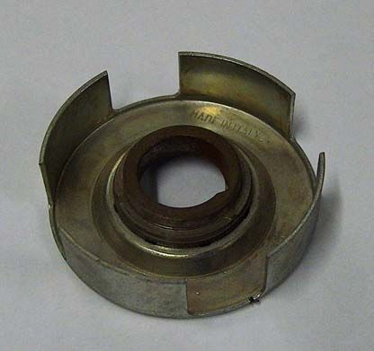
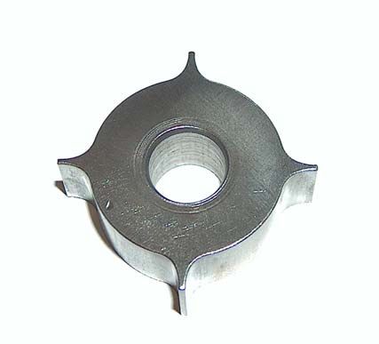
Bellow is examples of what a Hall Effect sensor looks like.
They need a Power Supply of 9V or 12V and Ground to
function correctly.
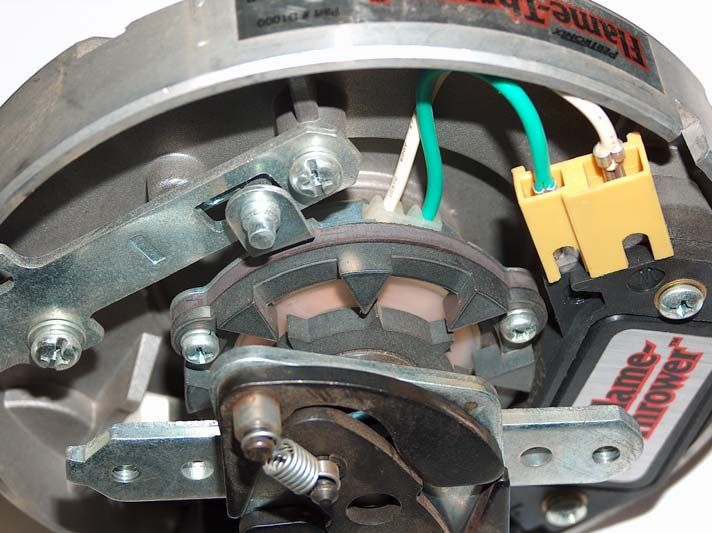
Typical chopper blade for Hall sensorBellow is an example of what an Optical sensor looks like. They need a Power Supply 5 V and Ground to function correctly. Below is a Nissan Crank angle sensor. Note the uneven slots on the trigger disk. Trigger disks with even spaced slots are available from your Dicktator agent for four and six cylinder Nissan engines.
Bellow is examples of what Magnetic sensors look like.
They need a magnetic converter to function correctly.
The best way to identify them is by looking for a coil in the
pick-up. They do not need a Power Supply but must be
grounded

                GM Style Magnetic Pick-Up

        Coil

              Toyota Style Magnetic Pick-Up

           Coil
The above picture shows a Toyota Trigger wheel with 24
teeth. Below is a replacement Trigger wheel for a four
cylinder Toyota with distributor. They are available for four
and six cylinder engines. Contact you Dicktator agent for
your requirements.
When you are using coil negative as trigger, you need to
open the cover of the Dicktator. Use solder and join the
two patches on the PC board.
Coil Neg
474J63- Do I need a magnetic converter? Only the magnetic type pick-up needs a magnetic converter to function correctly. There are different types of magnetic pick-ups. All the magnetic converter does is to convert a magnetic signal into an open collector type signal. Bellow is an example of a magnetic signal and what it looks like after it has been converted. The 60-2 box with magnetic input doesn’t need magnetic converters.
There are two common crank angle sensors in use:
       o Hall Effect (Mostly Siemens)
       o Magnetic ( Bosch)

As a general rule the sensor plug will indicate what type it
is.

                      Siemens (Hall)

                     Bosch (Magnetic)

- Fuel pumps

If the car you are modifying was fuel injection before the
modifications you shouldn’t have a problem with your fuel
pump. If the car was equipped with a carburetor or was
running on Diesel before the conversion, it is very
important to understand the following. Owners of very
high output engines who need to modify the fuel supply to
cater for the engines requirements should read as well.
At the coast water boils at 100°C and on top of Kilimanjaro
water boils at 81°C…….SO WHAT?

The boiling point of a liquid is the temperature at which the
vapour pressure of the liquid equals the environmental
pressure surrounding the liquid. A liquid in a vacuum
environment has a lower boiling point than when the liquid
is at atmospheric pressure. A liquid in a high pressure
environment has a higher boiling point than when the
liquid is at atmospheric pressure. In other words, the
boiling point of liquids varies with and depends on the
surrounding environmental pressure.
In short that means that your fuel pump should pump the
fuel and not suck it:
o Fit your fuel pump as close as possible to your fuel
tank.
o Fit your fuel pump below your fuel tank.
o Reduce any pressure drops before the pump.
o Shield your fuel pump and plumbing from heat.
o Fit Fuel filter before the pump to protect the pump.
o Fit high pressure filter after the pump to protect
injectors.
o Prevent suction from the top of the fuel tank.
If your metal fuel tank have to be modified to take suction
from the bottom it can normally be done by your local
radiator repair shop.
- Where to Dyno?
Very controversial question as you can imagine.
There are however a few things to look out for, to help you
finding the right tuner for your car:
o Does the tuner have a good quality LOADING
dyno?
o Does the tuner have a proper Air/Fuel ratio
meter and not one of the cheapies that uses a
narrowband lambda sensor? (LSM 11 excluded)
o Does tuner have a 4 or 5 gas analyzer? (It is
very important to spot problems during the
tuning)
o Does the tuner have a proper cooling fan with
motor of at least 5 kW?Connecting up the ECU
- Read and understand this manual.
- Disconnect your car’s battery negative.
- Unplug the harness connector from the Dicktator.
- Locate the ECU, ensuring that the wiring harness is
long enough to reach all components.
- Locate it away from any heat sources and prevent it
from getting wet.
- Feed wires through firewall and protect the wire
insulation against rubbing against the sharp metal
edges by using rubber grommets.
- Feed vacuum/boost sense pipe through same grommet.
- Connect vacuum pipe to the inlet manifold. Pipe must
be connected so that it senses manifold pressure with
throttle fully closed and not only when throttle is partially
open. (Do not connect vacuum pipe if TPS based map
is used)
- The Dicktator wiring harnesses are supplied without any
fuses. It is recommended that you fit a fuse at the
positive power connection (20 Amp). A fuse can also be
installed in the power supply to the fuel pump.
- Crimp pre insulated terminals to the thick red and thick
black wires and connect it to the battery terminals.
- Find the original power supply to the coil and connect
the thin red wire to it.
- Connect the harness connector to the Dicktator.
- Switch the ignition on.
- The red LED on the Dicktator should now be on.
- Now is a good time to connect your Laptop to the
Dicktator and see if there is power. The Coil charge
mode i.e. Constant charge time or constant duty
percentage must now be set.
- Very important is to set the coil trigger edge as well
before the coil is connected.
- Switch ignition off.
- Disconnect the battery negative.- Extend the short red/yellow wire to the fuel pump, crimp
a terminal onto it and connect the positive (Use wire of
similar gage or thicker)
- Connect the fuel pump negative with similar gage wire
to good earth.
- Connect the long red/yellow wire to all the positive sides
of the injectors (The positive side is the side that is
normally common on the original harness).
- Connect half the injectors to the one output (brown wire)
and the rest of the injectors to the other brown wire
- Connect the purple wire to one side of the water temp
sensor and a thin black wire to the other side.
- Connect the yellow wire to one side of the air temp
sensor and a thin black wire to the other side. (The air
temp sensor is not an absolute requirement for normally
aspirated engines).
- Connect the TPS:
o Red/White 5 V - positive
o Gray/Red or Gray/Blue - signal
o Thin Black – negative
- Connect the green trigger wire to the distributor or crank
angle sensor. (See installation drawings)
- Connect the white home signal wire to the cam sensor
or to the distributor with home signal. (Only required if
wasted spark box is used)
- Connect ignition output to igniter or directly to coil if
internal igniter is used.
- Determine if rev counter uses coil negative or 5 V
signal. Connect rev counter to blue/grey wire if 5 V
signal is used. If a wasted spark engine is fitted into a
car that had a coil negative rev counter and the original
rev counter is used, you might need a rev counter
booster/adapter.
- If there is cam control or a flap, connect relay or VTEC
driver. (See installation drawings)
- Connect the blue wire to one side of an idle control
motor and injector positive to the other wire. (Three wire
types can also be used????)ECU Plug pin functions and wire colours diagram
DICKTATOR ENGINE MANAGEMENT SYSTEM
20 PIN PLUG LAYOUT AS SEEN FROM HARNESS SIDE
All Multi Coloured W ires are always stated as : Main Colour / Stripe Colour
Position
Trigger
Home
Input
Input
10
20
Ignition White Ignition Green
Signal
Signal
Water
19
Air
TPS Yellow TPS Purple
9
Signal
Signal
POT
TPS
18
Green / Yellow TPS Grey / Red
8
Positive
Sensor
Output
Tacho
5 Volt
TPS (+5V) Ignition
17
7
Red / White Blue / Grey
Output 3
Ignition
Output
Flaps
Ignition Ignition
16
6
White / Black Yellow / Red
Output 2
Output 1
Ignition
Ignition
Ignition Ignition
15
5
Yellow / Green Yellow / Black
Positive
Injector
To Fuel
Relay
From
Battery (+12V)
14
Grey
4
Sensing Red
To Ignition
Negative
Switched
Control
+12V
13
Idle
Injector Blue Ignition Red
3
Negative
Injector
-VE
12
Injector Brown 2 Black
2
2
Negative
Injector
-VE
11
Injector Brown 1 Black
1
1
Short Thick
Fuel Pump
Red / Yellow
85
86
Main
Injector Relay +
Battery
87
30
Red / Yellow -• What igniters to use - Processor Controlled Ignitions (Smart Igniters) Earlier type igniters are known as intelligent igniters. They have a processor inside the igniter to control things like charge time, rev limiters and immobilizers. The most popular of the intelligent igniters is the “TP 100”. It was standard equipment on some German manufactured vehicles. Beware of the ones with the gray plastic cover, they are equipped with immobilizers and the pin configuration is different. When an intelligent igniter is used, it is preferred to set the Dwell Control to Constant Duty Percentage of 50%. - Dumb Igniters Modern igniters are all triggered from the car’s ECU. The charge time of the ignition coils are controlled by the ECU and there is no processor inside the igniter. Great care should be taken when these are used because if the wrong Spark Trigger Edge is selected the igniter and ignition coil will most definitely be damaged. The Dwell Control is set to Constant Charge Time. Start with a low value of ± 2 ms. and increase this value if needed. - Preferred Igniters Dicktator manufactures a range of igniters. They are all Dumb igniters with current limiting. It is recommended that a Dicktator igniter is used together with your Dicktator ECU. - Dicktator’s Single, Twin, Triple and Quad Igniters Dicktator manufactures igniters with 1, 2, 3, and four ignition channels. All the Dicktator igniters use the falling Spark Trigger Edge.
- No Igniter Required

In some cases the igniter is incorporated inside the ignition
coil. In these cases an igniter is not required. Examples of
ignition coils with internal igniters are:
                 o Volkswagen COP coils with 4 pins.
                 o New Volkswagen Polo with wasted
                    spark coil.
                 o Older Opel Corsa with wasted spark coil.
6. Glossary AFR - Air/Fuel Ratio ATDC - After Top Dead Center BAC - Bypass Air Control BTDC - Before Top Dead Center COP - Coil On Plug ECU - Engine Control Unit (Dicktator Box) EMI - Electromagnetic Interference IAC - Idle Air Control IGN - Ignition LED - Light Emitting Diode MAP - Manifold Absolute Pressure ms - Milliseconds NOS - Nitrous Oxide PC - Personal Computer POT - Potentiometer (Electronic) PWM - Pulse Width Modulation RAM - Random Access Momory RPM - Revolutions Per Minute TDC - Top Dead Center TPS - Throttle Position Sensor VGA - Video Graphics Display VTEC - Variable Valve-Timing and Lift Electronic Control WAT - Water
You can also read


