DEZURIK KGC-ES KNIFE GATE VALVES - 2-24" (50-600MM) - INSTRUCTION D10411 JANUARY 2023
←
→
Page content transcription
If your browser does not render page correctly, please read the page content below
DeZURIK KGC-ES
                           KNIFE GATE VALVES
                              2-24” (50-600mm)

                                                                                   Instruction D10411
                                                                                               January 2023

DeZURIK, Inc. Sartell, Minnesota USA | Phone: 320-259-2000 | www.dezurik.com | info@dezurik.com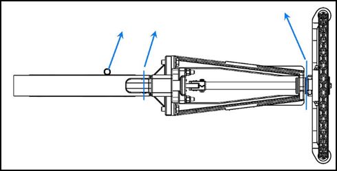
DeZURIK
Instructions
These instructions are for use by personnel who are responsible for the installation, operation and
maintenance of DeZURIK valves, actuators or accessories.

Safety Messages
All safety messages in the instructions are identified by a general warning sign and the signal word CAUTION,
WARNING or DANGER. These messages indicate procedures to avoid injury or death.
Safety label(s) on the product indicate hazards that can cause injury or death. If a safety label becomes difficult
to see or read, or if a label has been removed, please contact DeZURIK for replacement label(s).

Personnel involved in the installation or maintenance of valves should be constantly alert to potential
emission of pipeline material and take appropriate safety precautions. Always wear suitable protection
when dealing with hazardous pipeline materials. Handle valves which have been removed from service
with suitable protection for any potential pipeline material in the valve.

Inspection
Your DeZURIK product has been packaged to provide protection during shipment; however, items can be
damaged in transport. Carefully inspect the unit for damage upon arrival and file a claim with the carrier if
damage is apparent.

Parts
Replaceable wear parts are listed on the assembly drawing. These parts can be stocked to minimize
downtime. Order parts from your local DeZURIK sales representative or directly from DeZURIK. When ordering
parts please provide the following information:

   If the valve has a data plate: please include the 7-digit part number with either 4-digit revision number
   (example: 9999999R000) or 8-digit serial number (example: S1900001) whichever is applicable. The
   data plate will be attached to the valve assembly. Also, include the part name, the assembly drawing
   number, the balloon number and the quantity stated on the assembly drawing.
   If there isn't any data plate visible on the valve: please include valve model number, part name, and
   item number from the assembly drawing. You may contact your local DeZURIK Representative to help
   you identify your valve.

DeZURIK Service
DeZURIK service personnel are available to maintain and repair all DeZURIK products. DeZURIK also offers
customized training programs and consultation services. For more information, contact your local DeZURIK
sales representative or visit our website at DeZURIK.com.

Instruction and Operating Manual                     Page 2                                © 2023 DeZURIK, Inc.
DeZURIK
2-24” KGC ES KNIFE GATE VALVES

Table of Contents

Description                               4
Handling                                  4
Installation                              6
Operation                                 7
Lubrication                               7
Packing                                   7
Adjustment                                7
Drawings                                  8
Packing Replacement                       9
 Removing the Old Packing                 9
 Installing the New Packing               10
 Reassembling the Valve                   11
Seat Replacement                          11
 Reassembling the Valve                   12
Replacing the Gate                        12
Purge Port Option                         13
Troubleshooting                           15

January 2023                     Page 3
DeZURIK
2-24” KGC ES KNIFE GATE VALVES
Description
KGC knife gate valves have a stainless steel body and gate, and an all-metal or resilient-faced seat.
The KGC knife gate valve is available in 2-48" (50-1200mm) sizes. This manual covers the 2-24” (50-
600mm) sizes. A choice of several actuators and accessories is available.
Handling
The points below are for reference purposes only, use safe and proper lifting and support tech-
WARNING!
A potential hazard exists with handling valves. Failure to handle valves properly
may cause a valve to shift, slip or fall causing serious injury or death and/or
equipment damage.
niques. DO NOT lift valves with any adjoining pipe or other equipment attached. Lift with
properly rated lifting equipment. Follow jurisdictional safety requirements.
Suggested lifting points are as shown below to lift valve assemblies that are in a horizontal orientation.
Eye bolts in flange through holes can be used to lift the valve body or, for 2” through 12” valves, a
sling can be strapped around the top of the valve body.
For valves with bevel gear actuators, a sling or chain can a wrapped around the bevel gear actuator
body, between the mounting plate and the input shaft housing. This would be in conjunction with lift-
ing from the valve body as well. See Figure 1.
Figure 1— Knife Gate Valve with Bevel Gear Actuator,
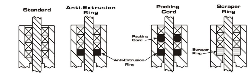
Horizontal Lifting For valves with pneumatic cylinder ac-
tuators, a sling can be wrapped around
the cylinder, near the cylinder head (piston rod end). This would be in conjunction with lifting from the
valve body. Utilize caution to not bump, dent or damage the cylinder tube. DO NOT utilize the cylin-
der tie-rod ends to lift. See Figure 2.
Figure 2, Knife Gate Valve with Pneumatic Cylinder Actuator,
Horizontal Lifting
D10411 Page 4 JanuaryDeZURIK
2-24” KGC ES KNIFE GATE VALVES
Handling continued
For valves with handwheel actuators, a sling or chain can be wrapped through the rim of the hand-
wheel. For chainwheel actuators, a sling can be wrapped in the area between the yoke/legs and the
chainwheel/guide assembly. This would be in conjunction with lifting from the valve body as well. See
Figure 3.
Figure 3, Knife Gate Valve with Handwheel or Chainwheel Actuator, Horizontal Lifting
Suggested lifting options are as shown below to lift valve assemblies that are in a vertical orientation.
For valves with bevel gear actuators, wrap slings or chains around the top of each leg. Use caution
not to put any side load on the bevel gear input shaft or on the valve’s threaded stem. See Figure 4.
For valves with pneumatic cylinder actuators, wrap slings around the top of each leg. Use caution to
not bump, dent or damage the cylinder tube and avoid any side load on the cylinder piston rod. DO
NOT utilize the cylinder tie-rod ends to lift. See Figure 5.
For valves with handwheel or chainwheel actuators, wrap slings or chains around the top of the each
leg or yoke side. Use caution to not put any side load on the valve’s threaded stem. See Figure 6.
Figure 4- Knife Gate Valve Figure 5- Knife Gate Valve Figure 6- Knife Gate
with Bevel Gear Actuator, with Pneumatic Cylinder Valve with Handwheel or
Vertical Lifting Actuator, Vertical Lifting Chainwheel Actuator,
Vertical Lifting
D10411 Page 5 JanuaryDeZURIK
2-24” KGC ES KNIFE GATE VALVES
Installation
Install the valve between ASME Class 125 or Class 150 pipeline flanges, or other flanges that match
valve end connection. Flange gaskets are required. Before installation, remove foreign material such
as weld spatter, oil, grease, and dirt from the valve and pipeline.
Normal Installations
Install the valve so that the side marked “SEAT” is on the lower pressure side of the valve when the
valve is closed; the pipeline pressure will then help seal the valve in the closed position.
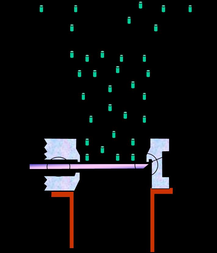
Gravity (Dry) Service Installations
When installing the valve in a vertical pipeline (such as a hopper
bottom, gravity flow, or other dry service application), install the
SEAT side of the valve facing upstream as shown in Figure 1.
Installing the valves with the seat side upstream prevents process
media buildup in the seat and chest area of the valve. This orien-
tation also allows the seat to act as an integral deflection cone,
protecting the seat from wear.
General Guidelines
Observe the following points to prevent distortion of the valve
body and gate when the flange bolts are tightened:
• Align the mating pipeline flanges.
• Select the length of the flange bolts so that the bolts
used in the blind holes near the chest area of the valve
Figure 1—Vertical Line/
do not bottom out when tightened. We recommend
using studs with nuts in the blind holes. Hopper Bottom
Table A: Recommended Flange Bolt/Stud
• Tighten the flange bolts evenly, in a
crisscross pattern. Refer to Table Torque Range in ft-lbs (non-lubricated)
A for recommended flange bolt/
stud torques. ASME Gasket Types
Rubber with
Note: Torque ranges are based on ASME Valve Size
Soft Fabric Fill- Soft Elastomer
Pressure Vessel Code Calculations and er, & 1/8” Thick Gasket Shore
lab test data. These torques are only for Hard Durometer < 75A
the listed gasket types. For other gasket 2” (50mm) 26 - 29 8-9
types listed in ASME, consult DeZURIK.
3” (80mm) 37 - 41 14 - 16
After installing the valve, pressurize pipeline 4” (100mm) 26 - 29 11 - 12
and ensure the packing is not leaking. If the 6” (150mm) 41 - 45 22 - 24
packing leaks, adjust the packing as described 8” (200mm) 55 - 61 35 - 39
on the next page. 10” (250mm) 56 - 62 40 - 44
12” (300mm) 80 - 88 59 - 65
14” (350mm) 107 - 118 81 - 89
16” (400mm) 103 - 114 79 - 87
18” (450mm) 128 - 141 102 - 112
20” (500mm) 123 - 136 99 - 109
24” (600mm) 188 - 207 155 - 171
D10411 Page 6 JanuaryDeZURIK
2-24” KGC ES KNIFE GATE VALVES
Operation
The gate in the valve is positioned by the valve actuator. The actuator moves the gate over the valve
port in the closed position, and withdraws the gate from the seat in the open position. Refer to the Ac-
tuator Instructions for adjustment and maintenance requirements for the actuator.
Lubrication
The valve does not require lubrication. If applicable, ensure that valve threaded stems are maintained
with proper lubrication. Refer to the Actuator Instructions for lubrication requirements for the actuator.
Packing
The gate packing is contained and compressed by the packing gland. See Figure 2 for component
identification.
Note: The packing gland is slightly loosened prior to shipping. This is done to increase the life of the
packing during extended storage.
Adjustment
If packing leaks, tighten the adjustment nuts on top of the packing gland. Tighten the nuts evenly and
gently just enough to stop the leak. Over tightening will cause excessive operating forces, and will de-
crease the life of the packing.
January 2023 Page 7DeZURIK
2-24” KGC ES KNIFE GATE VALVES
Drawings
Bolt (A5)
Nut (A7)
Washer (A6)
Gate (A3)
Packing Gland (A4)
Packing (A2)
Packing Cord (A8) (if supplied)
Packing (A2)
Anti Extrusion Ring (A9)
(if supplied)
Body (A1)
Seat (A10)
Body (A1)
Removable Seat Detail
Figure 2—Component Identification
D10411 Page 8 JanuaryDeZURIK
2-24” KGC ES KNIFE GATE VALVES
Packing Replacement
Removing the Old Packing
1. Relieve the pressure in the pipeline and close the valve.
WARNING!
Pipeline pressure can cause personal injury or equipment damage. Relieve pipe-
line pressure before removing gate stem and packing gland nuts.
WARNING!
Accidental operation of power actuator can cause personal injury or equipment
damage. Disconnect and lock out power to actuator before servicing.
2. If the actuator is powered, disconnect and lock out power to prevent accidental operation of the ac-
tuator.
3. Remove the two screws and nuts near the top of the gate and disengage the stem from the gate by
stroking the actuator (not the valve) to the open position.
4. Remove the gland nuts (A7), bolts (A5) and packing gland (A4).
5. Remove the used packing (A2), anti-extrusion ring (A9) if supplied and packing cord (A8) if sup-
plied, from the packing chamber.
January 2023 Page 9DeZURIK
2-24” KGC ES KNIFE GATE VALVES
Installing the New Packing
Packing (A2) strip length and quantity are shown in Table B. Ensure the inside and outside edges of
each ring are packed against the gate and packing chamber, so that each strip is compressed flat
and evenly. DeZURIK provides extra packing in their packing kits, but do not try to put more packing
into a layer than shown in Table B. If packing is for low pressure applications (40psi [2.7 bar]) contact
DeZURIK.
Table B: Packing Ring and Packing Cord
Do not compress the packing any more than Length & Quantity
needed to stop leaks. Valve Size Square Length, Qty
Size inches Quantity Cord
1. Ensure the gate (A3) is fully closed and cen-
tered in the body before packing. 2” (50mm) 7.50
2. If used, place the anti-extrusion ring (A9) or 3” (80mm) 9.50 4 w/o
scraper ring in the bottom of the packing anti-ext
4” (100mm) 11.50 ring or
chamber. 3/8”
5” (125mm) 13.50 cord
Note: Ensure that the anti-extrusion ring fits 6” (150mm) 15.50
tightly around the gate and that there is approxi-
mately 1/32-1/16" clearance around the packing 8” (200mm) 20.00
chamber.
10” (250mm) 25.00 1
3. Assemble and pack the rings one at a time, 12” (300mm) 29.00
with the ends together, but not overlapped 1/2” 3 w/o
14” (350mm) 32.00 cord
Note: Stagger the joints, on the long side of the 16” (400mm) 36.75
packing chamber. For packing rings, we recom-
mend using a square-ended wood or plastic tool, 18” (450mm) 41.25
driven by a hammer or mallet. Do not use a 2 with
sharp tool to pack the rings. 20” (500mm) 5/8” 45.25 cord
24” (600mm) 53.50
4. For packing systems with the packing cord
(A8), assemble and pack one row of packing (A2) and then insert the packing cord (A8). Assem-
ble and pack the last row of packing. See detail below:
Packing Scraper
Standard Cord Ring
Packing (A2)
Packing (A2)
Packing
Cord
(A8)
Scraper
Ring
(A9)
Anti-Extrusion
Ring
(A9) if supplied
Figure 3—
Packing Ring
Detail
D10411 Page 10 JanuaryDeZURIK
2-24” KGC ES KNIFE GATE VALVES
Reassembling Valve
1. Replace the packing gland (A4), bolts (A5), washer (A6) and nuts (A7). Tighten the nuts evenly
and finger tight, plus 1/2 turn.
2. Reconnect the stem to the gate with the two screws and nuts.
3. If the actuator is a powered actuator, reconnect power to the actuator.
4. Pressurize the pipeline and inspect packing for leakage.
5. If packing leaks, tighten the adjustment nuts on top of the packing gland. Tighten the nuts evenly
and gently - just enough to stop the leak. Over tightening will cause excessive operating forces,
and will decrease the life of the packing.
Replacing the Seat
See Figure 2 for component identification.
1. Relieve the pressure in the pipeline and close the valve.
WARNING!
Pipeline pressure can cause personal injury or equipment damage. Relieve pipe-
line pressure before removing gate stem and packing gland nuts.
2. If the actuator is powered, disconnect and lock out power to prevent accidental operation of the
WARNING!
Accidental operation of power actuator can cause personal injury or equipment
damage. Disconnect and lock out power to actuator before servicing.
actuator.
3. Remove the two screws and nuts near the top of the gate and disengage the stem from the gate.
4. Remove the pipeline flange bolts and flange from the side of the valve body opposite the word
“SEAT”. As an alternative, remove both flanges, and remove the valve from the pipeline.
5. Remove the actuator yoke and actuator from the valve.
6. Remove the gland nuts (A7), washers (A6), and packing gland (A4).
7. Remove the gate (A3) from the body. Seat (A10)
8. Remove the packing (A2) from the packing chamber.
9. Remove the seat. Push the top of the removable seat (A10)
toward the center of the valve, and remove the seat
through the packing chamber. Body (A1)
10. Install the new replaceable seat:
a. Note the gate side and body side of the seat as
shown in Figure 4.
b. Insert the new seat (A10) through the packing Figure 4—Seat
chamber.
c. Place the seat behind the lug at the 5 and 7 o‘clock positions in the body. Then push the
top of the seat into position.
January 2023 Page 11DeZURIK
2-24” KGC ES KNIFE GATE VALVES
Seat Replacement Continued
Reassembling the Valve
1. Reassemble the gate (A3) in the body, with the beveled edge facing away from the resilient seat.
See Figure 4.
2. Place the gate in the fully closed position.
3. Reassemble the packing, as described in “Installing New Packing”.
4. Reassemble the packing gland (A4), washers (A6), nuts (A7) and bolts (A5). Tighten the nuts
evenly to finger tight, plus 1/2 turn.
5. Reassemble the yoke and actuator on the valve.
6. Reconnect the stem to the gate with the two screws and locknuts.
7. Reassemble the pipeline flange and flange bolts, or reassemble the valve in the pipeline if the
valve was removed. Refer to the requirements in the “Installation” section.
8. If the actuator is a powered actuator, reconnect power to the actuator.
9. Pressurize the pipeline and inspect the valve for leaks.
10. If the packing leaks, tighten the adjustment nuts (A7) on top of the packing gland. Tighten the nuts
evenly and slowly, just enough to stop the leakage. Over tightening will cause excessive operating
forces, and will decrease the life of the packing.
Replacing the Gate
See Figure 2 for component identification.
1. Relieve the pressure in the pipeline and close the valve.
2. If the actuator is powered, disconnect and lock out power to prevent accidental operation of the
WARNING!
Pipeline pressure can cause personal injury or equipment damage. Relieve pipe-
line pressure before removing gate stem and packing gland nuts.
actuator.
WARNING!
Accidental operation of power actuator can cause personal injury or equipment
damage. Disconnect and lock out power to actuator before servicing.
3. Remove the pipeline flange bolts, and remove the valve from the pipeline.
4. Remove the actuator, actuator yoke, packing gland (A4), and packing (A2) from the valve.
5. Remove and inspect the gate (A3). If the gate appears to be scratched or galled due to too-long
flange bolts in the chest area of the body, check for body damage in the tapped flange holes and
within the chest cavity. Carefully check the seat for damage. Repair or replace the body, as appro-
priate.
D10411 Page 12 JanuaryDeZURIK
2-24” KGC ES KNIFE GATE VALVES
Gate Replacement Continued
6. Remove and inspect the seat components.
7. Replace or reinstall the seat components as described in step 10 in the “Seat Replacement “ sec-
tion.
8. Place the new gate (A3) in the body, in the fully closed position.
9. Replace or reinstall the packing (A2) as described in “Installing New Packing”.
10. Replace the yoke and actuator on the valve.
11. Adjust the actuator, yoke, and packing gland so that the valve actuates smoothly full stroke in both
directions, and so that there is no evidence of binding or scratching on the gate when the gate is
visible in the fully open position.
12. Reinstall the valve in the pipe line —see “Installation” section.
13. If the actuator is a powered actuator, reconnect power to the actuator.
14. Pressurize the pipeline and inspect the valve for leaks.
15. If the packing leaks, tighten the adjustment nuts (A7) on top of the packing gland.
Note: Tighten the nuts evenly and slowly, just enough to stop the leakage. Over tightening will cause
excessive operating forces, and will decrease the life of the packing.
Purge Port Option
When purge port options are ordered as illustrated, the intent is that the installer will connect purge
lines.
Installation:
WARNING!
If pipeline is under pressure with purge port plugs in place, release line pressure
before removing plugs. Serious or fatal injury may occur if not complied with.
1. Remove all purge plugs after valve has been installed in line and before line is pressurized.
2. Connect proper purge line to the ports.
3. Pressurize purge lines and check for leaks.
4. Pressurize pipe line.
See Figure 5 for Purge Port sizes and locations.
January 2023 Page 13DeZURIK
2-24” KGC ES KNIFE GATE VALVES
Purge Port Options
VALVE SIZE
INCH MM A
2 50
3 80
1/4 ”
4 100
5 125
6 150
8 200
3/8 ”
10 250
12 300
14 350
1/2 ”
16 400
18 450
20 500 3/4 ”
24 600
Figure 5—Purge Port Sizes and Locations
D10411 Page 14 JanuaryDeZURIK
2-24” KGC ES KNIFE GATE VALVES
Troubleshooting
Corrective
Condition Possible Causes Action
Packing is loose Adjust packing gland
Packing leaks, with no evidence
of galling on gate
Packing is worn or torn Replace packing
Replace packing and
Packing leaks and gate is galled Packing is worn or torn gate, check seat for
damage
Valve leaks when fully closed,
with no evidence of galling on Seat is worn or torn Replace seat
gate
Valve leaks when fully closed and
Seat is worn or torn Replace gate and seat
gate is galled
January 2023 Page 15Limited Warranty
DeZURIK, Inc. (“Seller”) manufactured products, auxiliaries and parts thereof that we manufacture for a period of twenty-four (24) months from date
of shipment from Seller’s factory, are warranted to the original purchaser only against defective workmanship and material, but only if properly stored,
installed, operated, and serviced in accordance with Seller’s recommendations and instructions.
For items proven to be defective within the warranty period, your exclusive remedy under this limited warranty is repair or replacement of the defective
item, at Seller’s option, FCA Incoterms 2020 Seller’s facility with removal, transportation, and installation at your cost.
Products or parts manufactured by others but furnished by Seller are not covered by this limited warranty. Seller may provide repair or replacement
for other’s products or parts only to the extent provided in and honored by the original manufacturer’s warranty to Seller, in each case subject to the
limitations contained in the original manufacturer’s warranty.
No claim for transportation, labor, or special or consequential damages or any other loss, cost or damage is being provided in this limited warranty.
You shall be solely responsible for determining suitability for use and in no event shall Seller be liable in this respect.
This limited warranty does not warrant that any Seller product or part is resistant to corrosion, erosion, abrasion or other sources of failure, nor does
Seller warrant a minimum length of service.
Your failure to give written notice to us of any alleged defect under this warranty within twenty (20) days of its discovery, or attempts by someone other
than Seller or its authorized representatives to remedy the alleged defects therein, or failure to return product or parts for repair or replacement as
herein provided, or failure to store, install, or operate said products and parts according to the recommendations and instructions furnished by Seller
shall be a waiver by you of all rights under this limited warranty.
This limited warranty is voided by any misuse, modification, abuse or alteration of Seller’s product or part, accident, fire, flood or other Act of God, or
your failure to pay entire contract price when due.
The foregoing limited warranty shall be null and void if, after shipment from our factory, the item is modified in any way or a component of another
manufacturer, such as but not limited to; an actuator is attached to the item by anyone other than a Seller factory authorized service personnel.
All orders accepted shall be deemed accepted subject to this limited warranty, which shall be exclusive of any other or previ ous warranty, and this
shall be the only effective guarantee or warranty binding on Seller, despite anything to the contrary contained in the purchase order or represented by
any agent or employee of Seller in writing or otherwise, notwithstanding, including but not limited to implied warranties.
THE FOREGOING REPAIR AND REPLACEMENT LIMITED WARRANTY IS IN LIEU OF ALL OTHER WARRANTIES, OBLIGATIONS AND
LIABILITIES, INCLUDING, BUT NOT LIMITED TO, ALL WARRANTIES OF FITNESS FOR A PARTICULAR PURPOSE OR OF MERCHANTABILITY
OR OTHERWISE, EXPRESSED OR IMPLIED IN FACT OR BY LAW, AND STATE SELLER’S ENTIRE AND EXCLUSIVE LIABILITY AND YOUR
EXCLUSIVE REMEDY FOR ANY CLAIM IN CONNECTION WITH THE SALE AND FURNISHING OF SERVICES, GOODS OR PARTS, THEIR
DESIGN, SUITABILITY FOR USE, INSTALLATION OR OPERATIONS. NEITHER ANY PERFORMANCE OR OTHER CONDUCT, NOR ANY ORAL
OR WRITTEN INFORMATION, STATEMENT, OR ADVICE PREPARED BY SELLER OR ANY OF OUR EMPLOYEES OR AGENTS WILL CREATE A
WARRANTY, OR IN ANY WAY INCREASE THE SCOPE OR DURATION OF THE LIMITED WARRANTY.
Disclaimer
Metric fasteners should not be used with ASME Class 150/300 bolt holes and flange bolt patterns. If you use metric fasteners with ASME Class 150/300
bolt holes and flange bolt patterns, it may lead to product failure, injury, and loss of life. DeZURIK Inc. disclaims all liability associated with the use of
metric fasteners with ASME Class 150/300 bolt holes and flange patterns, including but not limited to personal injury, loss of life, loss of product,
production time, equipment, property damage, lost profits, consequential damages of any kind and environment damage and/or cleanup. Use of metric
fasteners with ASME Class 150/300 bolt holes and flange bolt patterns is a misuse that voids all warranties and contractual assurances. If you use
metric fasteners with ASME Class 150/300 bolt holes and flange bolt patterns, you do so at your sole risk and any liability associated with such use shall
not be the responsibility of DeZURIK, Inc. In addition to the foregoing, DeZURIK’s Manufacturer’s Conditions apply.
Limitation of Liability
IN NO EVENT SHALL SELLER BE LIABLE FOR ANY DIRECT, INDIRECT, SPECIAL, PUNITIVE, EXEMPLARY, OR CONSEQUENTIAL DAMAGES
(INCLUDING, BUT NOT LIMITED TO; DAMAGE TO OR LOSS OF OTHER PROPERTY OR EQUIPMENT, BUSINESS INTERUPTION, COST OF
SUBSTITUTE PRODUCTS, LOSS OF TIME, LOSS OF PROFITS OR REVENUE, COST OF CAPTIAL, LOSS OF USE, OR DIMINUTION IN VALUE)
WHATSOEVER, AND SELLER’S LIABILITY, UNDER NO CIRCUMSTANCES, WILL EXCEED THE CONTRACT PRICE FOR THE GOODS AND/OR
SERVICES FOR WHICH LIABILITY IS CLAIMED. ANY ACTION FOR BREACH OF CONTRACT BY YOU, OTHER THAN RIGHTS RESPECTING OUR
LIMITED WARRANTY DESCRIBED ABOVE, MUST BE COMMENCED WITHIN 12 MONTHS AFTER THE DATE OF SALE.
Sales and Service
For information about our worldwide locations, approvals, certifications and local representative:
Web site: www.dezurik.com E-Mail: info@dezurik.com
250 Riverside Ave. N., Sartell, MN 56377 ● Phone: 320-259-2000 ● Fax: 320-259-2227
DeZURIK, Inc. reserves the right to incorporate our latest design and material changes without notice or obligation.
Design features, materials of construction and dimensional data, as described in this manual, are provided for your information only
and should not be relied upon unless confirmed in writing by DeZURIK, Inc. Certified drawings are available upon request.
December 2022You can also read