DESIGN NARRATIVE 100% DESIGN SUBMISSION FY21 - MCNAIR GROUP 01 QUARTERS 10 15 - USACE - NATIONAL CAPITAL PLANNING ...
←
→
Page content transcription
If your browser does not render page correctly, please read the page content below
Design Narrative
100% Design Submission
FY21 - McNair Group 01 Quarters 10 - 15

USACE

Project reference: JBMHH Army Family Housing
Project number: 60615576

June 09, 2021
Design Narrative
                      Project reference: JBMHH Family Housing
                       Solicitation Number – W912DR21BXXXX

Prepared for: USACE                                  AECOM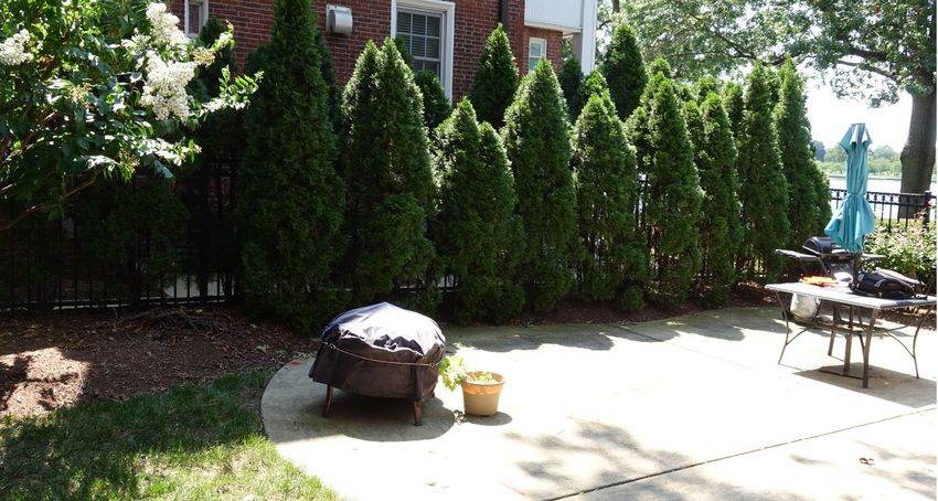
Design Narrative
                                                                                       Project reference: JBMHH Family Housing
                                                                                        Solicitation Number – W912DR21BXXXX

                 Quality information
                     Prepared                      Checked                   Verified by                      Approved
                     by                            by                                                         by
                     Blank                         Blank                     Blank                            Blank

                     Krista                        Joshua                    Ryan                             Krista
                     Kehrer                        Levy                      Horner/Troy                      Kehrer
                     Project                                                 Metz
                     Manager

                 Revision History
Revision                        Revision               Details            Authorized                Name                    Position
                                  date
           0                    Blank                  Blank              Blank                     Blank                   Blank
        Blank                   Blank                  Blank              Blank                     Blank                   Blank
        Blank                   Blank                  Blank              Blank                     Blank                   Blank
        Blank                   Blank                  Blank              Blank                     Blank                   Blank

                 Distribution List
                 # Hard                    PDF                   Association / Company Name
                 Copies                    Required
                 Blank                     Blank                 Blank
                 Blank                     Blank                 Blank
                 Blank                     Blank                 Blank
                 Blank                     Blank                 blank

  Prepared for: USACE                                                                                                 AECOM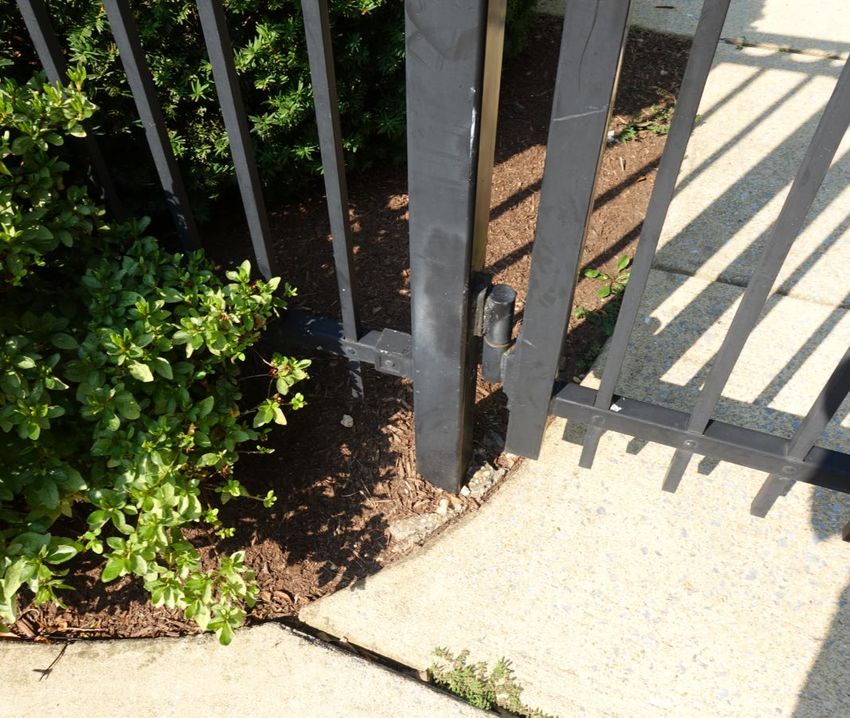
Design Narrative
                                                                              Project reference: JBMHH Family Housing
                                                                               Solicitation Number – W912DR21BXXXX

               Prepared for:
USACE W912DR21BXXXX -W912DR19F0647
Vivian Wong
2 Hopkins Plaza
Baltimore, MD 21201

               Prepared by:
Krista Kehrer
Project Manager
T: 703-682-4973
M: 703-867-7948
E: krista.kehrer@aecom.com

AECOM
3101 Wilson Boulevard
Arlington, VA 22201
aecom.com

               Copyright © 2019 by AECOM

               All rights reserved. No part of this copyrighted work may be reproduced, distributed, or
               transmitted in any form or by any means without the prior written permission of AECOM.

Prepared for: USACE                                                                                          AECOM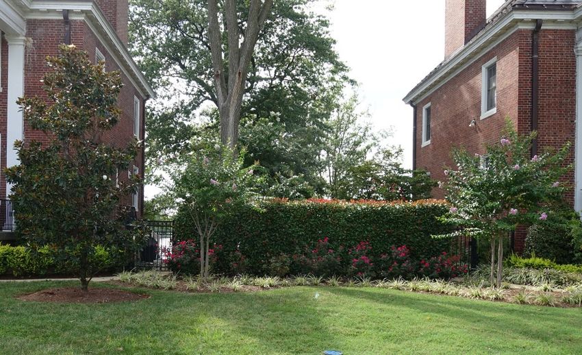
Design Narrative
                                                                                                               Project reference: JBMHH Family Housing
                                                                                                                Solicitation Number – W912DR21BXXXX

Table of Contents
1.         General Description ......................................................................................7
2.         Design Requirements and Provisions Building Group 01 Quarters 10 -
15         13
2.1.1      Civil .......................................................................................................................................... 13
2.1.2      Landscape Architecture ............................................................................................................. 19
2.1.3      Structural .................................................................................................................................. 23
2.1.4      Architecture............................................................................................................................... 25
2.1.5      Fire Protection / Life Safety ....................................................................................................... 51

Prepared for: USACE                                                                                                                                AECOM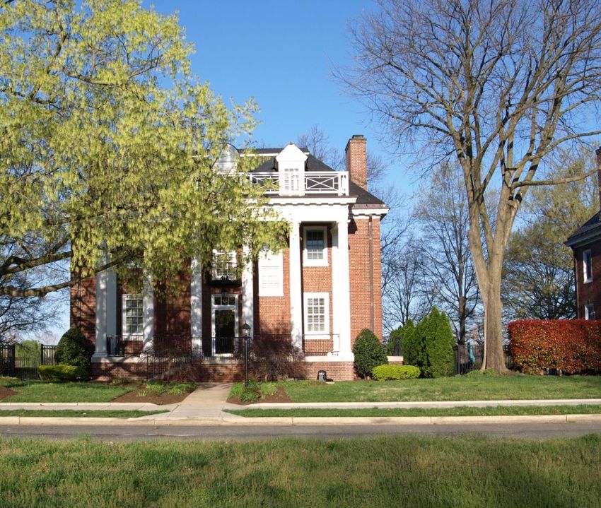
Design Narrative
                                                           Project reference: JBMHH Family Housing
                                                            Solicitation Number – W912DR21BXXXX

                      This Page Intentionally Left Blank

Prepared for: USACE                                                                       AECOM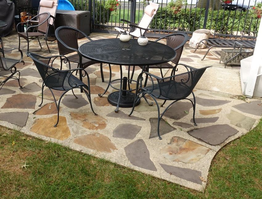
Design Narrative
                                                                               Project reference: JBMHH Family Housing
                                                                                               Project number: 60615576

1. General Description
1.1 Introduction
               The Design Narrative summarizes AECOM’s Design Documents in accordance with the 28
               January 2021 Scope of Work (SOW) for the Joint Base Myer Henderson Hall (JBMHH) project
               in addition to the Final Design Charrette Reports for FY21 dated 10 February 2021. The
               programming effort assessed the conditions of 12 historical family housing units at Fort Myer
               and Fort McNair and provide Architecture and Engineering documents to bring these housing
               units back into good repair. The housing units cover FY21 anticipated designs.

               FY21 – McNair Group 01 Quarters 10-15 (Single Family)
               FY21 – Myer Group 11 Quarters 08 (Single Family)

               This report will cover the existing conditions and requirements for McNair Group 01 Quarters
               10-15.

1.2 Project Drawings
               This project’s drawings for the Design Charrette Report have been prepared using Autodesk
               Revit 2019 and Enterprise CADD Standard Version 6.0. Select civil and sitework drawings
               have been prepared using a three-dimensional AutoCAD platform. As per the SOW, AECOM
               has prepared the project documents using Imperial units of measure only.

1.3 Specifications
               The project’s specifications sections indicate the proposed editing in SpecsIntact – the
               automated system for preparing standardized facility construction specifications that is used
               worldwide by the U.S. Army Corps of Engineers (USACE), National Aeronautics and Space
               Administration (NASA) and the U.S. Naval Facilities Engineering Command (NAVFAC).

1.4 Construction Cost Estimates
               Estimates for each respective phase of construction have been prepared in accordance with
               Unified Facilities Criteria (UFC) 3-700-02A – Construction Cost Estimates using the military‘s
               Micro Computer Aided Cost Engineering System (MCASES) II software platform.

               The estimates were prepared as a result of close collaboration between the project design
               team and the cost estimating team.

               Estimates are broken down into Base Bid and Bid Options per the funding amounts outlined in
               the scope of work.

1.5 Report Criteria
               This Report is based on the USACE, Baltimore District, Instructions and Guidance to Architect-
               Engineers Military Construction and the Department of the Army, USACE, Engineering and
               Design Analysis, Drawings and Specifications.

               All documentation has been prepared in accordance with AECOM‘s contract specific Design
               Quality control Plan (DQCP). AECOM is an International Standards Organization (ISO) 9001
               certified organization.

Prepared for: USACE W912DR19D0013-W912DR19F0647                                                                AECOM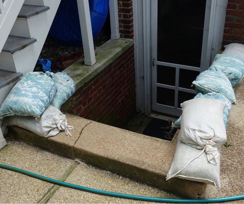
Design Narrative
                                                                             Project reference: JBMHH Family Housing
                                                                                             Project number: 60615576

1.6 Codes, Standards and Guidelines
1.6.1 International Code Council (ICC) Model Codes
               •   International Residential Code (IRC) 2018
               •   International Building Code (IBC) 2018
               •   International Existing Building Code (IEBC) 2015
               •   International Plumbing Code (IPC) 2018 - Classification Residential, Occupancy R-3, One-
                   and two-family dwellings

1.6.2 National Fire Protection Association (NFPA)
               •   NFPA-70A, National Electrical Code Requirements for One- and Two- Family Dwellings,
                   latest edition including all subsequent addendums 2005 Edition
               •   NFPA-75, Standard for the Protection of Information Technology Equipment 2003 Edition
                   Intra-Building Pathway Systems
               •   NFPA-72, National Fire Alarm and Signaling Code 2019 Edition
               •   NFPA-13D, Standard for Installation of Sprinkler Systems in One- and Two-Family
                   Dwellings and Manufactured Homes 2019 Edition
               •   NFPA-101, Life Safety Code 2018 Edition
               •   NFPA-110, Standard for Emergency and Standby Power Systems 2019 Edition
               •   NFPA-780, Lightning Protection Systems 2020 Edition

1.6.3 Industry Standards and Guidelines
1.6.3.1 American Society of Civil Engineers (ASCE)
               •   ASCE/SEI 7-16, Minimum Design Loads and Associated Criteria for Buildings and Other
                   Structures

1.6.3.2 American Society of Heating, Refrigeration and Air Conditioning Engineers
        (ASHRAE)
               •   ASHRAE Fundamentals 2013
               •   ASHRAE 90.2, 2010, Energy-Efficient Design of Low-Rise Residential Buildings
               •   ASHRAE 62.2, 2010, Ventilation and Acceptable Indoor Air Quality in Low-Rise
                   Residential Buildings
               •   ASHRAE Standard 140, 2017, Standard Method of Test for the Evaluation of Building
                   Energy Analysis Computer Programs

1.6.3.3 Building Industry Consulting Service International (BICSI)
               •   BICSI Telecommunications Distribution Methods Manual, latest edition

1.6.3.4 American Society of Testing and Materials (ASTM)
               •   ASTM D 5778, Seismic Piezocone Penetration Tests (SCPTu)
               •   ASTM D 6635, Flat Plate Dilatometer Testing (DMT)

Prepared for: USACE W912DR19D0013-W912DR19F0647                                                              AECOM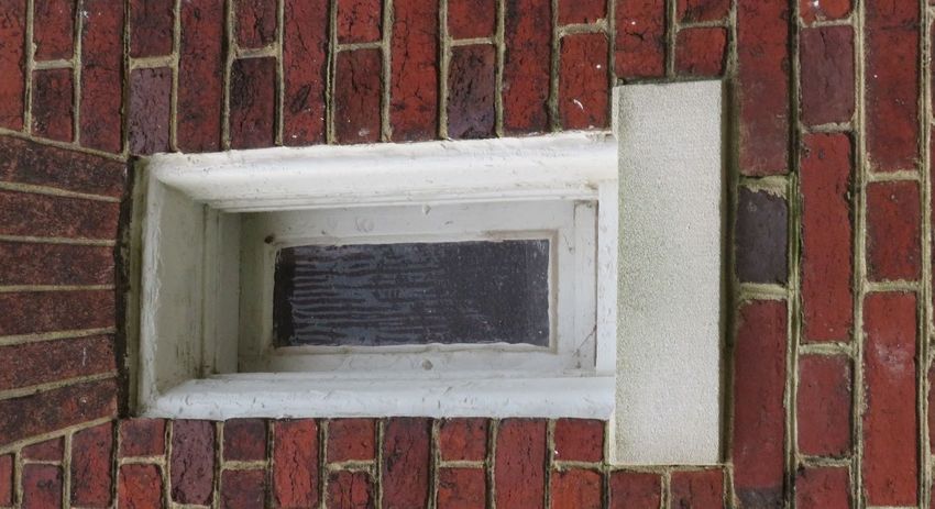
Design Narrative
                                                                              Project reference: JBMHH Family Housing
                                                                                              Project number: 60615576

               •   ASTM D 4719, Prebored Pressumeter Tests (PMT)
               •   ASTM E119, Standard Test Methods for Fire Tests of Building Construction and Materials

1.6.3.5 American National Standards Institute (ANSI)
               •   ANSI/TIA-569-E, Telecommunications Pathways and Spaces

               •   ANSI/TIA-570-D, Residential Telecommunications Infrastructure

               •   ANSI/TIA-606-C, Administration Standard for Telecommunications Infrastructure

               •   ANSI/TIA-607-D, Generic Telecommunications Bonding and Grounding (Earthing) for
                   Customer Premises

1.6.3.6 Underwriter's Laboratory (UL)
               •   UL 263, Standards for Fire Tests of Building Construction and Materials

1.6.3.7 American Society for Photogrammetry and Remote Sensing (ASPRS)
               •   Accuracy Standards for Photogrammetry and Remote Sensing Accuracy Standards for
                   Large Scale Maps

               •   Manual of Photogrammetry

1.6.4 Federal Government Legislation, Regulations, Standards and
      Guidelines
1.6.4.1 Unified Facilities Criteria (UFC)
               •   UFC 1-200-01, General Building Requirements (08 October 2019)

               •   UFC 1-200-02, High Performance Sustainable Building (HPSB) Requirements, Change 4
                   (1 October 2019)

               •   UFC 1-300-02, Unified Facilities Guide Specifications

               •   UFC 1-300-08, Criteria for Transfer and Acceptance of DoD Real Property

               •   UFC 3-101-01, Architecture with Change 5, 25 September 2019

               •   UFC 3-110-03, Roofing with Change 4, 01 May 2012

               •   UFC 3-120-10, Interior Design, 15 May 2018

               •   UFC 3-190-06, Protective Coatings and Paints, 16 January 2004

               •   UFC 3-201-01 Civil Engineering

               •   UFC 3-230-01 Water Storage and Distribution

               •   UFC 3-230-17FA Drainage in Areas Other than Airfields

               •   UFC 3-240-07FA Sanitary and Industrial Wastewater Collection: Gravity Sewers and
                   Appurtenances

               •   UFC 3-301-01, Structural Engineering (01 October 2019)

               •   UFC 3-410-01, Heating Ventilation and Air Conditioning Systems, 01 July 2013 Change
                   05, 01 Nov 2019

Prepared for: USACE W912DR19D0013-W912DR19F0647                                                               AECOM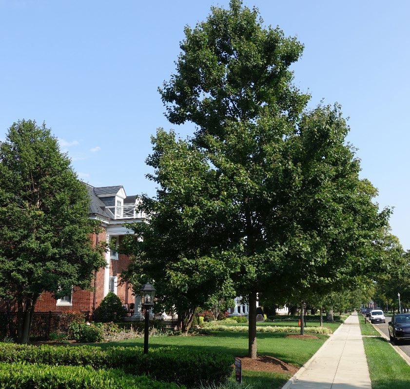
Design Narrative
                                                                             Project reference: JBMHH Family Housing
                                                                                             Project number: 60615576

               •   UFC 3-420-01, Plumbing Systems, Plumbing Systems, 25 October 2016 Change 04, 01
                   OCT 2019

               •   UFC 3-520-01, Interior Electrical Systems, 06 October 2015 Change 01, 20 March 2019

               •   UFC3-530-01, Interior and Exterior Lighting Systems and Controls, 01 April 2015 Change
                   04, 01 November 2019

               •   UFC 3-600-01, Fire Protection Engineering for Facilities (08 August 2016, Change 4, 07
                   February 2020)

               •   UFC 3-700-02A, Construction Cost Estimates Using the Military's Micro Computer Aided
                   Cost Engineering System (MCASES) II Software Platform

               •   UFC 3-701-01, DoD Facilities Pricing Guide

               •   UFC 3-730-01, Programming Cost Estimates for Military Construction

               •   UFC 3-740-05, Handbook: Construction Cost Estimating

               •   UFC 4-010-01, DoD Minimum Antiterrorism Standards for Buildings (12 December 2018)

               •   UFC 4-010-06, Cybersecurity of Facility-Related Control Systems, Change 1

               •   UFC 4-711-01, Family Housing

               •   UFC 4-711-02A, U.S. Army Service Schools

1.6.4.2 United States Army Corps. Of Engineers (USACE)
               Engineering and Construction Bulletin (ECB)

               •   ECB 2018-11, Control System Cybersecurity Coordination Requirement, dated 09 August
                   2018

               Engineering Manual (EM)

               •   EM 385-1-1, Safety and Health Regulations

               •   EM 1110-1-1000, Photogrammetric Mapping

               •   EM 1110-1-1002, Survey Markers and Monumentation

               •   EM 1110-1-1003, NAVSTAR Global Positioning System Surveying

               •   EM 1110-1-1005, Topographic Surveying

               •   EM 1110-2-1003, Hydrographic Surveying

               Engineering Regulation

               •   ER-1110-1-261, Quality Assurance of Laboratory Testing Procedures

               •   ER 1110-345-700, Design Analysis

               •   ER-1110-345-723, Total Building Commissioning Procedures, dated 31 March 2017

Prepared for: USACE W912DR19D0013-W912DR19F0647                                                              AECOM
Design Narrative
Project reference: JBMHH Family Housing
Project number: 60615576
1.6.5 Other Guidelines, Codes, Regulations and Local Utility
Requirements
1.6.5.1 Installation Guidelines
• Joint Base Real Property Master Plan Fort Myer Fort McNair Henderson Hall Installation
Design Guide, January 2013 (IDG)
1.6.5.2 Local Municipalities
• 2013 District of Columbia Plumbing Code
• District of Columbia Stormwater Management Guidebook
• District of Columbia Erosion and Sediment Control Handbook
• District of Columbia DC Water Project Design Manual
1.6.5.3 Other
• Load Calculation Program – Trane Trace 700 in accordance with ASHRAE Standard 140
• https://geopub.epa.gov/Radon/
1.7 Bid Options
The requirements for these quarters will include construction bid options. The options are
outlined in this report and on the matrix found in Appendix A. The base requirements are
intended to improve the life, health, safety of the buildings. The bid option expands the
renovations to improve the function of each quarters.
Prepared for: USACE W912DR19D0013-W912DR19F0647 AECOMDesign Narrative
Project reference: JBMHH Family Housing
Project number: 60615576
This Page Intentionally Left Blank
Prepared for: USACE W912DR19D0013-W912DR19F0647 AECOMDesign Narrative
Project reference: JBMHH Family Housing
Solicitation Number – W912DR21BXXXX
2. Design Requirements and Provisions
Building Group 01 Quarters 10 - 15
2.1 Building Group 01 Quarters 10 - 15
2.1.1 Civil
2.1.1.1 Existing Conditions
The Group 01 quarters at Fort McNair are single family dwellings aligned in a row fronting the
west side of 2nd Avenue which runs north south. The buildings are spaced approximately 40
feet apart, set back approximately 50 feet from 2nd Avenue, with a rear yard also approximately
50 feet from 1st Avenue which parallels 2nd Avenue. It is noted that the avenue numbering
system within Fort McNair is not coordinated with the street numbering system outside Fort
McNair in the District of Columbia, Southwest (DC SW). Each quarters have a fenced-in
concrete patio on its south side (left as you face the house from 2nd Avenue) with the exception
of Quarters 15 which has its patio on the north side. There is a total of 15 units in the row,
numbered from north to south. The scope of the current effort encompasses Quarters 10 – 15
only.
In preparing this report a comprehensive integrated review of GIS documents, historic design
documents, topographic survey data, geophysical subsurface utility survey data, and field
observations was conducted to resolve any discrepancies among the data sources. Where
available information was insufficient to resolve a particular issue, the contractor is directed to
conduct further investigation (e.g., test pits) during construction to avoid conflicts.
2.1.1.1.1 Grading
Topographic grades along 1st and 2nd Avenues are extremely flat – less than 0.3% based on a
topographic survey conducted by AECOM in October 2020. There is also very little slope from
the building fronts to the curb on 2nd Avenue, and between quarters. There is a comparatively
shallow gradient from the back yards down to 1st Avenue, but over time settling, landscaping
activities, utility work, etc. have resulted in localized low spots where water ponds in the yards
and around the building foundations. Some of the quarters were observed with sandbags
stacked around exterior basement stairwells to prevent surface runoff into the basements, and
post staff have stated that all of these buildings have basement/foundation water problems.
Photo 1 – Sandbags Stacked by Basement Stairs Quarters 12
Prepared for: USACE AECOMDesign Narrative
Project reference: JBMHH Family Housing
Solicitation Number – W912DR21BXXXX
2.1.1.1.2 Stormwater
Utility record drawings prepared by STV/Lyon Associates dated July 1996 were compared
against GIS utility maps provided by the installation and found to be consistent with one
another, and generally with field observations.
Surface drainage from the front yards of Quarters 12 through 15 flows overland east to 2nd
Avenue where it would be captured by a pair of storm drain inlets (catch basins) in the west
curb line of the street – one between Quarters 11 and 12, and one just southeast of Quarters
13. That water would then be conveyed by a small (12-inch) stormwater main running between
Quarters 11 and 12 to discharge into the tidal Washington Channel west of 1st Avenue. Runoff
in the rear yard flows west to 1st Avenue where there is a pair of inlets similarly located in the
east curb line of that street to collect the drainage. These inlets also carry stormwater to the
point of discharge into the Channel. Drainage from Quarters 10 and 11 flows in these two
streets a few hundred feet further to the north and is then similarly collected from the front
yards in inlets in 2nd Avenue, and from the rear yards in inlets in 1st Avenue, then conveyed
westward in pipes to an outlet into the Channel.
The Washington Channel is far enough removed both horizontally (almost 100 feet), and
vertically (at least 10 feet) from the structures that it has not been identified as a significant
source of the water problems for these buildings and is not considered further in this
discussion. Current FEMA flood mapping indicates that none of these quarters is within a
regulatory 100-year floodplain, though portions of the rear yards nearest 1st Avenue are.
Each of the houses has multiple roof drain downspouts, almost all of which discharge directly
into an underground pipe or leader. Some of these leaders may possibly be connected to
small (4-inch) diameter plastic drainpipes that have been cut through the curb line in 1st
Avenue, though no mapping was found that would indicate the route or location of these
connections. No visible signs of clogged or backed up roof drains were observed.
Photo 2 – Possible Roof Drain through Cut in Curb Quarters 10
Prepared for: USACE AECOMDesign Narrative
Project reference: JBMHH Family Housing
Solicitation Number – W912DR21BXXXX
Basement sump pumps also contribute to stormwater flow by discharging either into the
underground roof drain system, or directly to the ground surface.
Quarters-specific issues or deficiencies are noted below:
• Quarters 11, 12, 13, 15: sandbags stored near the exterior basement stairwell (northwest
corner) indicate periodic surface water flooding
• Quarters 14: this Quarters was visited during a rainstorm and ponded water was
observed directly adjacent to the southwest corner of the building foundation.
Photo 3 – Ponding at Roof Drain by Foundation Quarters 14
2.1.1.1.3 Water
Utility record drawings prepared by STV/Lyon Associates dated July 1996, and Maryland
Surveying and Engineering Co. (undated) were compared against GIS utility maps provided by
the installation and found to be generally, but not completely, consistent with one another.
The GIS maps and record drawings indicate that water is provided to Fort McNair via a 12-
inch feeder main connection in 4th Street SW. This connection is metered, but there are no
meters for these homes individually. The quarters in Group 01 are served by an 8-inch
distribution branch main running in the front yards of the quarters parallel to 2nd Avenue.
House water services are depicted with a single service line between adjacent buildings,
branching to serve both buildings, e.g., one line between Quarters 10 and 11, branching to
serve both; one line between Quarters 12 and 13, branching to serve both, etc. There is
supposed to be a valve on the primary service line at the main, and a valve on each of the
branches near the building, but no water meters. The Maryland Surveying Co. drawings
indicate that these house service lines are 3-inch diameter; however, the GIS maps show the
service lines as 2-inch diameter.
Fire hydrants serving these quarters were found on 2nd Avenue just north of the subject area
at the front of Quarters 9, between Quarters 12 and 13, and just south of the group near the
southeast corner of Building 60 (the old Officers Club). Fire flow pressure test results were
Prepared for: USACE AECOMDesign Narrative
Project reference: JBMHH Family Housing
Solicitation Number – W912DR21BXXXX
provided by the government for tests conducted at these hydrants in May 2020. These tests
indicated satisfactory flow capacity (approximately 2200 gpm at a desired flow rate of 20 psi).
Quarters-specific issues or deficiencies are noted below:
• Quarters 10 and 11: drawings and GIS indicate that a single water service line serving
both Quarters 10 and 11 should be located near the south side of Quarters 10. Records
also show a water service valve near the main in the front yard of Quarters 10, and a
valve near the outside wall of each house. The record drawings show an additional valve
on the main line in front of Quarters 11. A water valve box was found in the field in the
front yard of Quarters 10 positioned consistent with a valve on the main (not on a
service). A possible inference is that this was installed instead of the main line valve
shown on the drawings in front of Quarters 11. A valve box for the shared service line was
field located near the main between the building fronts. A third valve box was found where
the service enters the north side of Quarters 11, but no equivalent valve box was found
for Quarters 10. A fourth metal subsurface feature with a broken top/cap was found in the
front yard between the two Quarters. It’s size, material, and position could be consistent
with that of a valve box, but its function could not be identified.
• Quarters 12 and 13: the valves for the primary service line between Quarters 12 and 13,
and for the individual service branch at the south face of Quarters 12 were found in the
field (in addition to the operating valve for the fire hydrant between the buildings), but the
corresponding service valve for Quarters 13 was not.
• Quarters 14 and 15: GIS and record drawings indicate that a single water service line
serving both Quarters 14 and 15 should be located roughly between the two buildings,
with a primary service valve near the main in the front yard and a valve near the outside
wall of each house. A valve box for the shared service line was field located near the main
between the building fronts, and a valve box was found where the service enters the
north side of Quarters 15, but no corresponding valve box was found for Quarters 14. A
third valve box found in the yard southeast of Quarters 15 might be on the main, though
its position would be more consistent with a valve on a service line.
2.1.1.1.4 Sewer
Utility record drawings prepared by STV/Lyon Associates dated August 1994, and GIS utility
maps provided by the installation were consulted and found to be generally, but not
completely, consistent with field observations.
The records indicate that the quarters in Group 01 are served by an 8-inch clay sanitary sewer
collector main running in the front yards of the buildings parallel to 2nd Avenue. This collector
drains northward, turning east at a manhole in front of Quarters 11, running across the parade
ground, eventually discharging into the city wastewater system in 2nd Street SW near T Street.
House sewer services are configured with a single service line between adjacent buildings,
branching to serve both buildings, e.g., one line between Quarters 11 and 12, branching to
serve both; one line between Quarters 13 and 14, branching to serve both. The records show
a single cleanout on the shared service line at the branching point. The exceptions are that
Quarters 15 is paired on a service line with Building 60, and Quarters 10 is on a shared
service line with Quarters 9 (which is drained by a different main running toward P Street SW).
Records indicate that the shared part of the service line is a 6-inch diameter pipe, while the
individual branches are each 4 inches.
Quarters-specific issues or deficiencies are noted below:
• Quarters 10 through 14: None of the sanitary cleanouts shown on the record drawings
between these Quarters could be located during field investigations.
• No cleanout was found for Quarters 15, but a direct sanitary service connection from the
house to a manhole between the quarters and Building 60 was located.
Prepared for: USACE AECOMDesign Narrative
Project reference: JBMHH Family Housing
Solicitation Number – W912DR21BXXXX
2.1.1.1.5 Gas
Utility record drawings prepared by STV/Lyon Associates dated August 1994, and GIS utility
maps provided by the installation were consulted and found to be generally, but not
completely, consistent with field observations.
The records indicate that the quarters in Group 01 are served by a 10-inch ductile iron (DI)
main running in the rear yards of the buildings parallel to 1st Avenue. Each quarters is fed by a
2-inch coated wrapped steel (CWS) service line running from the main to the north side of the
house, Both sets of records show an exterior shutoff valve on each service line, but none of
these were located in the field investigations. A gas valve was found in the rear yard of
Quarters 15, but its position is consistent with a main line valve shown on the drawings, not a
service line valve. Gas meter assemblies were found in the interior basements of Quarters 10
and 15, but not in any of the others.
According to the STV drawings gas service is supplied to Fort McNair by Washington Gas
(formerly Washington Gas Light Company), but the gas distribution equipment on-post is
owned and operated by the U.S. Government.
2.1.1.2 Functional and Technical Requirements
2.1.1.2.1 Grading
Foundation leakage and infiltration were observed in Group 01 Quarters during the interior
surveys and documented in the Facility Condition Assessment (FCA). Failed grading that
results in water ponding around and adjacent to the buildings will contribute to this issue.
Multiple buildings in this group were found with sandbags stacked around the exterior
basement stairwell indicating a history of surface water flooding. Government direction
provided during the Programming and Charrette meetings in November and December 2020
and documented in the Programming Findings agreed with AECOM’s recommendation for
minor regrading of the lots to direct runoff away from the buildings as part of the foundation
repair and waterproofing process. This perimeter excavation will require the reconstruction of
sidewalks and patios within the limits of disturbance.
2.1.1.2.2 Stormwater
As part of the response to the foundation leakage issues discussed above, Government
direction provided during the Programming and Charrette meetings in November and
December 2020 and documented in the Programming Findings agreed with AECOM’s
recommendation to connect all downspouts and basement sump pumps to underground drain
pipes to convey drainage away from the structures as part of the foundation repair and
waterproofing process.
The Group 01 quarters are not within the limits of a delineated 100-year floodplain; however,
exterior excavation proposed to remedy foundation leaks could trigger requirements under
DC’s Department of Energy & Environment (DOEE) erosion and sediment control (ESC) and
stormwater management (SWM) regulations. The extent of the measures required is based on
the combination of total land disturbance for all quarters and the ratio of cost of improvements
vs. replacement. AECOM anticipates that the cost of improvements for the Base Bid will likely
exceed 50% of the total value of the houses, which would place the project in a category of
SWM requirements that is more stringent than the minimum under DC regulations. Design for
SWM requirements is being evaluated and will provide bio-retention facilities behind each
Quarter towards 1st Avenue. The bio-retention areas are designed to collect as much of the
roof leaders, sidewalks, and patio runoff at each Quarters as feasible. An underdrain will be
provided for each bioretention basin to outfall at 1st Avenue. The Design Team has had several
discussions with DOEE about the stormwater retention volume requirements that cannot be
met with the bioretention basins behind the Group 01 quarters. Additional offsite stormwater
Prepared for: USACE AECOMDesign Narrative
Project reference: JBMHH Family Housing
Solicitation Number – W912DR21BXXXX
management areas will be investigated with DPW Environmental to plan for providing
stormwater credit for these quarters and other upcoming quarters construction.
2.1.1.2.3 Water
For the buildings in this group water services are configured with a single service line between
adjacent buildings, branching to serve both buildings. Some water service shutoff valves
depicted in record documentation could not be located by field efforts indicating a condition
wherein water service to an individual quarters could not be turned off for repairs without
potentially requiring the shutoff of one or more neighboring units. Government direction
provided during the Programming and Charrette meetings in November and December 2020,
and in the response to RFI 0034 agreed with AECOM’s recommendation to install new shutoff
valves on those service lines where an existing valve in good working order cannot be found
(Quarters 10, 13, and 14). This work is included as part of Bid Option 5, not under the Base
Bid.
2.1.1.2.4 Sewer
House sewer services for the quarters in this group are configured with a single service line
between adjacent buildings, branching to serve both buildings. Sanitary cleanout stacks
depicted in record documentation could not be located by field efforts indicating a condition
wherein maintenance to an individual quarters requiring interruption of service could not be
done without potentially disabling service for one or more neighboring units. Government
direction provided during the Programming and Charrette meetings in November and
December 2020 and documented in the Programming Findings agreed with AECOM’s
recommendation that due to the preferred location of sanitary cleanouts within a few feet of a
building’s exterior wall, it would be cost effective to install individual cleanouts on the separate
service lines (one for each house) as part of the foundation repair and waterproofing process.
This work will be done under the Base Bid.
2.1.1.2.5 Gas
For the buildings in Group 01 gas service shutoff valves depicted in record documentation
could not be located by field efforts which indicates a potential life/health/safety issue, because
in the event of an emergency it may be necessary to enter the building to shut off the gas
service. This condition was not addressed directly for the Group 01 quarters during the
Programming and Charrette meetings in November and December 2020; however, for
consistency with Government direction provided for the Group 15 and 16 quarters, and in the
response to RFI 0035, AECOM includes installation of new shutoff valves on all six service
lines (Quarters 10 – 15) under the Base Bid .
See the Plumbing Section 2.1.6 for additional details.
2.1.1.3 Calculations
Calculations will be provided on the design drawings and initial DOEE stormwater
management spreadsheets will be provided in a calculation appendix.
Prepared for: USACE AECOMDesign Narrative
Project reference: JBMHH Family Housing
Solicitation Number – W912DR21BXXXX
2.1.2 Landscape Architecture
2.1.2.1 Existing Conditions
The Group 01 buildings (10-15) or Generals’ Quarters are located between 2nd Avenue to the
west and to 1st Avenue to the east and run parallel to the Washington Channel of the Potomac
River. These buildings were built in the early 20th century as part of the 1903 Beaux Arts
master plan by the architectural firm of McKim Mead and White. While the buildings were
designed to frame the vista down the quadrangle to the War College Building (61), it is unclear
whether the landscape design for the Group 01 Quarters was original to the design. Mature
trees line both 1st Avenue, characterized by White Oaks and Willow Oaks, and much of 2nd
Avenue, characterized by Red Maples. The exception is Quarters 15 where the 2nd Avenue
frontage features Crape Myrtles instead of Red Maples, a significant difference in the scale,
shape, and color of the street trees. The eastern 2/3 of the site slopes towards 1st Avenue and
the seawall of the Washington Channel. The western 1/3 of the site slopes more gradually
towards 2nd Avenue. The houses are sited on the ridge dividing the eastern and western
portions of the site. While the grading is mostly consistent, depressions, swales, and divots
occur in several locations throughout the site.
Photo 4 - Quarters 13 View from 2nd Avenue Photo 5 - 2nd Avenue Featuring Tree Line of Red
Maple (Acer rubrum)
Each landscape in Group 01 is characterized by three zones: the open perimeter, the
enclosed patio, and the rear yard.
The open perimeter contains walkways, light posts, turf, specimen plants, and screening
plants. Walkways in the perimeter appear to be well maintained with a few noticeable cracks
and some incidental spalling. Concrete and stone surfaces under the house gutters are often
stained by copper, most likely from the gutters, and occasionally by rust, most likely from the
integrated railings. Entry to the basement from the exterior of the building is typically from the
northwest of the building, east of the northwest walkway. Light posts and signage appear to be
well maintained. Plantings are unique to each building. Screening plants do not consistently
screen the foundations of the quarters but generally appear to be in good condition. Turf
appears well maintained but the soil beneath appears to be severely compacted at places.
Although the lawn surface does not appear to be eroding or holding water, observation during
a rain event showed that soils do not allow water to infiltrate well.
Prepared for: USACE AECOMDesign Narrative
Project reference: JBMHH Family Housing
Solicitation Number – W912DR21BXXXX
Photo 6 - Quarters 12 North Walkway Photo 7 - Quarters 15 Exterior Stair to Basement
The enclosed patio features fences, fence screening plants, foundation screening plants,
specimen plants, and a cast-in-place terrace. The treatment and shape of the terrace is
different for each building. However, the buildings’ planting layout and grading solution seem
generally consistent.
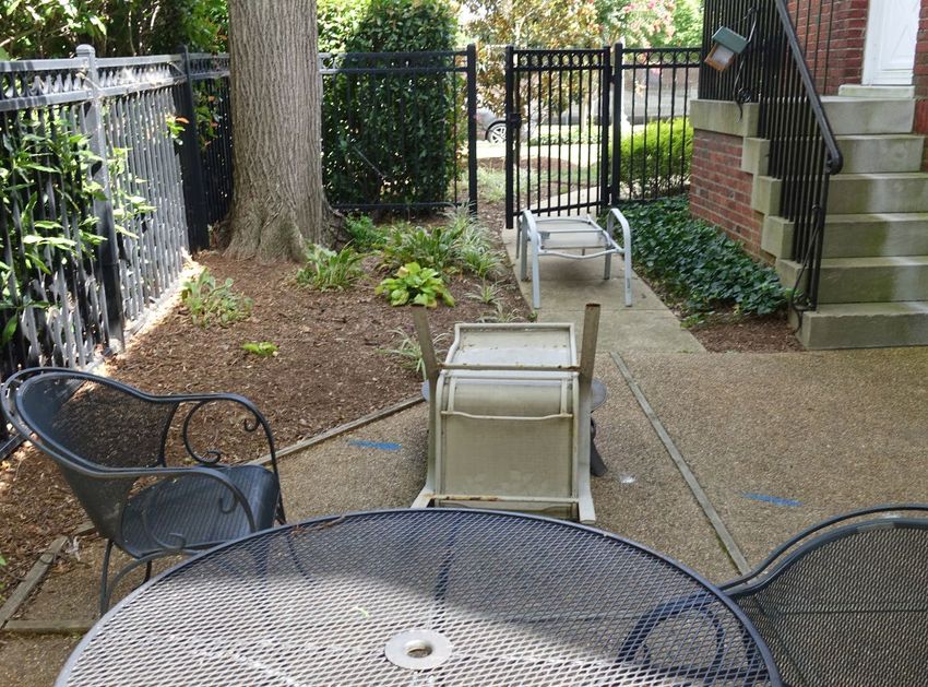
Photo 8 – View of the Exterior of the Enclosed Patio to Photo 9 - Enclosed Patio to the South of Quarters 12
the East (typical) Featuring White Cedar (Thuja occidentalis)
Screen
Photo 10 - Quarters 10 Enclosed Stone-Set-In- Photo 11 - Enclosed Patio to the North of Quarters 15
Concrete Patio Surface
Prepared for: USACE AECOMDesign Narrative
Project reference: JBMHH Family Housing
Solicitation Number – W912DR21BXXXX
Fence footings are often exposed and show signs of deterioration. The treatments of the edge
differ for each building. Foundation screening plants are inconsistent; an analysis of the
original desired planting plan would be of benefit to further evaluate their historic relevance.
Otherwise, those specimen plants seem to be in good condition.
Photo 12 – Exposed Footing and Missing Expansion Photo 13 – Liriope and Hydrangea Foundation
Joint at Quarters 11 East Gate Plantings within Enclosed Patios of Quarter 12
The front yard has a lawn area, street trees, lamp posts, and occasionally foundation planting
at each building. The perimeter is intermittently planted with Liriope and Holly at the base of
the buildings. Those landscape elements are in good condition.
Photo 14 – Front Yard Specimen Holly Tree (Ilex Photo 15 – Front Yard Walkway Border Plantings
opaca) Quarters 11 at Quarters 12
The rear yard has a large turf area, street trees, lamp posts, and occasionally screening plants
along the base of the perimeter of the building. Turf grass appears dry, especially near
walkways. Lamp posts along 1st Avenue are of a different color and style than those along 2nd
Avenue. Holly and intermittent Liriope screen the base of the building; it appears to be in good
condition.
Prepared for: USACE AECOMDesign Narrative
Project reference: JBMHH Family Housing
Solicitation Number – W912DR21BXXXX
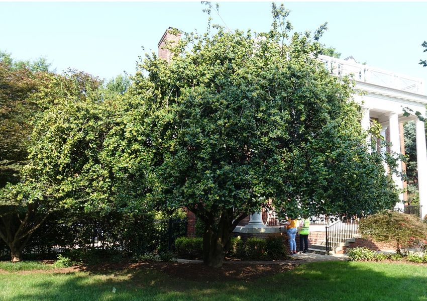
Photo 16 - Tree Line along First Avenue Photo 17 -Screening Plants for Rear Photo 18 -Screening Plants for Rear
Quarters 15 (Taxus baccata) Quarters 10 (Ilex aquifolium)
2.1.2.2 Functional and Technical Requirements
Demolition as part of the work includes removal of plants, turf, soil, and hardscape to facilitate
foundation work. Soil is stored at a location that does not interfere building modifications, site
modifications, or movement around the site, Trees are isolated from construction activity and
protected from injury. For the base bid, pavement and hardscape removal are primarily
around the perimeter of the quarters, though removal may occur in other locations in order to
implement the proposed design. For Bid Option 1 additional turf and landscape elements are
removed to the south of quarters 15 to provide a patio area comparable to those of the other
Group 01 quarters. For Bid Option 2 undesirable plants and all exterior hardscape associated
with the quarters are removed so that new concrete will match in quality and aesthetics.
The design includes stormwater features, hardscape amendments, and required regrading of
the site. The Base Bid scope incorporates provisions for tree preservation, the restoration of
plantings and fencing in areas affected by construction activities, and the proposed stormwater
and bioretention landscape. Bid Option 1 includes extended concrete surfaces, screening for
mechanical units to the north of the quarters, and patio space to the south for Quarters 15.
The Bid Option 2 scope replaces and repairs landscape and hardscape elements throughout
the entirety of the sites. As they are removed, invasive and undesirable plant species are
replaced with plants recommended in the Installation Design Guide (IDG). The landscape,
hardscape, and other site elements proposed support and reinforce the building design
concept, promote the pedestrian environment, enhance the occupant experience, conform to
applicable physical security guidelines, and meet the requirements of the IDG. The design
performs without permanent irrigation systems. Temporary irrigation may be used during the
establishment period for plants.
Prepared for: USACE AECOMDesign Narrative
Project reference: JBMHH Family Housing
Solicitation Number – W912DR21BXXXX
2.1.3 Structural
2.1.3.1 Existing Conditions
The Group 01 Quarters including Quarters 10 through 15 are three level single family quarters
with full basements. The Quarters were constructed between 1903 and 1905 with exterior load
bearing brick masonry walls and wood bearing walls and joists in the interior. Each home has
a two-level enclosed porch at the rear of the building which includes a concrete slab at the first
level and wood framing for the remainder of the floor, wall, and roof construction. The exact
configuration of the structural framing is not known due to the absence of original construction
documents.
A limited structural survey was conducted by AECOM in June, July, and August 2020 to
observe the building conditions and deficiencies identified in the Facilities Condition
Assessment (FCA). The FCA was based on findings from surveys conducted in early 2018.
The FCA, DD Form 1391, and Course of Action (COA) documents outlined the deficiencies in
each building and the remediation requirements.
A geotechnical investigation of the soils and sub surface bearing conditions was
recommended in the FCA for all Group 01 Quarters including Quarters 10 through 15. The
FCA identified exterior masonry wall cracks, uneven floors, water infiltration though the
foundation walls and slab, and basement slab cracks which may be an effect of building
settlement. A previous structural engineering study and a geotechnical investigation were
prepared for Quarter 6 in 2011 and 2012 respectively. The geotechnical recommendations for
Quarter 6 included foundation remediation at that time.
The condition of the structural framing was observed where visible during the site surveys and
the deficiencies reported in the FCA were confirmed by AECOM. Cracks in the basement slab,
masonry wall cracks, and water infiltration were observed to be typical for all Group 01
Quarters.
The rear enclosed porches have deficiencies including uneven floors and deterioration of the
first level concrete framing. Where the concrete framing was exposed to view cracks, spalls,
and corroded reinforcement were common throughout the Group 01 Quarters. Longitudinal
cracks were observed on the underside of the perimeter concrete beams at Quarters 12.
Cracks and out of plane movement were observed in the brick masonry foundation wall and
piers supporting the porch framing. Observed conditions of the second-floor porch framing
included unevenness and sloped framing but were not consistent among Group 01 Quarters.
The rear porches were enclosed after the original construction and the variations between
buildings may have resulted from different approaches to renovations over time.
2.1.3.2 Functional and Technical Requirements
In accordance with UFC 4-711-01, the building code criteria applicable to detached one and
two-family dwellings not more than three stories in height above grade will comply with all
sections of the International Residential Code (IRC) 2018 and reference codes and standards.
Design elements beyond the limits of applicably for IRC will comply with IBC, UFC, and the
reference standards of each. The Design Criteria loads were developed for the controlling
code loads. The IRC design wind velocity controlled over the UFC criteria and is used for the
Design Criteria. The UFC seismic ground motion values were used for the Design Criteria.
In accordance with UFC 4-010-01 (12 December 2018) DoD Minimum Antiterrorism Standards
for Buildings, low occupancy family housing with 12 units or fewer are exempt from the
requirements of the UFC 4-010-01 standard.
Prepared for: USACE AECOMDesign Narrative
Project reference: JBMHH Family Housing
Solicitation Number – W912DR21BXXXX
In accordance with UFC 3-301-01 (1 October 2019) Structural Engineering, buildings in
Seismic Design Category B are exempt from the requirements for the seismic evaluation and
retrofit of existing buildings in the UFC 3-301-01 standard.
Design Criteria:
Ground Snow Load: 25 psf
Wind Speed: 115 mph (ultimate) per the IRC 2018
Seismic Data:
Site Class: D
Ss: 0.133g
S1: 0.043g
Sds: 0.143g
Sd1: 0.069g
Seismic Design Category: B
A geotechnical engineering study has been conducted by AECOM for the Group 01 Quarters.
The findings and recommendations of the geotechnical investigation for the Group 01
Quarters included remediation measures of the foundations. The 2012 Quarter 6 geotechnical
investigation recommended the installation of helical piers approximately 25 feet long and
spaced at 5 feet maximum along bearing walls to arrest building settlement and provide new
foundation bearing. All new foundations in the Group 01 Quarters will be supported by helical
piers including the rear porches. The size, layout, and depth of the helical piers will be
determined by the helical pier delegated design engineer. Based on preliminary findings from
the borings and consultation with helical pier vendors the typical pier length is anticipated to be
40 feet. Helical piers up to 55 feet may be required based on the foundation loads and soil
conditions.
The structural scope includes repairs to the deficiencies identified in the FCA and the AECOM
site survey along with new design elements related to the renovation of the Group 01
Quarters. Remediation of the foundation will be coordinated with architecture to include
masonry repairs and waterproofing of the exterior basement walls. Exterior foundation
drainage and under slab drainage will be installed at each quarters. The basement slab-on-
grade will be demolished and replaced at each Group 01 quarters. Enlargement of the door
opening between the master bedroom and the adjacent room will be coordinated with
architecture as part of Bid Option 1. Mechanical openings through the existing structural
framing will be coordinated with mechanical where required as part of Bid Option 1.
Supplemental framing will be provided where equipment weights exceed the capacity of the
existing floor joists.
Due to the existing conditions and the use requirements, the rear porches will be removed and
replaced at each of the Group 01 Quarters. Replacement of the exterior porch will be designed
to replicate the existing construction including a concrete slab and beam system at the first
level and wood floor and wall framing for the level two and roof structure. Details of the new
porch structure will be coordinated with the architectural requirements.
2.1.3.3 Calculations
Calculations can be found in Appendix B.
Prepared for: USACE AECOMDesign Narrative
Project reference: JBMHH Family Housing
Solicitation Number – W912DR21BXXXX
2.1.4 Architecture
Group 01 quarters in this scope of work includes Quarters 10, 11, 12, 13, 14 and 15. The
quarters are located at the south end of Group 01, fronting Second Avenue, and overlooking
First Avenue and the Washington Channel. The residences were constructed as single-family
officer homes from plans dated 1902.
The Fort McNair Historic District was listed on the National Register of Historic Places in 1975.
All residences, including Group 01, contribute as cultural resources under Criterion C as they
retain historic integrity of their planning and design by McKim, Mead and White. They are not,
however, individually or as a group listed structures. Based on this location the Installation
Design Guide places the quarters within the Historic District Theme.
McKim, Mead and White chose Colonial Revival as the design style for the houses at the then
newly planned Army War College, now known as Fort McNair. Common features and elements
of this style include symmetry, double hung windows, pitched roofs with dormers, columned
front porches, and shaped white trim on 3-bay or 5-bay plan configurations with either a brick
or horizontal wood siding envelope. The quarters employ all these elements using a 3-bay
configuration and brick envelope.
Photo 19 Group 01 Quarters Photo 20 - Historic NARA Photograph circa WWII
Photo 21 – Quarters 12 - Typical Front Elevation Photo 22 – Quarters 10 - Typical Rear Elevation
2.1.4.1 Existing Conditions
Fort McNair Quarters 10, 11, 12, 13, 14 and 15 were surveyed in April (Quarters 13), August,
September, October, and November 2020. The exterior and interior of all the houses are in
Prepared for: USACE AECOMDesign Narrative
Project reference: JBMHH Family Housing
Solicitation Number – W912DR21BXXXX
acceptable to good condition with noted exceptions and exhibit a range of apparent or nearly
original and new architectural elements and finishes.
Information described below has been gathered through original drawings limited to a few floor
plans and several structural plans and sections, dimensioned plans dated September 1997,
direct observation, historical photographs, and the previous Facility Condition Assessments
dated April 2019. Renovation, repair, or remodeling drawings delineating changes over time
are not available for review. No intrusive exploration has been conducted at the time of this
report for these specific quarters however an intrusive survey of Group 01 Quarters 4 was
conducted in June 2020; as Quarters 4 is substantially similar to these quarters, it can be
assumed that conditions uncovered during that investigation are similar to Quarters 10 -15.
2.1.4.1.1 Masonry
Based on observations of the interior basement walls, the exterior envelope appears to be
multiple wythes of masonry with an interior plaster finish. Although plaster with expanded
metal on wood lath is visible on certain interior basement ceilings and walls, intrusive surveys
of the first floor of Quarters 4 indicates plaster directly applied to the inside face of the exterior
wall.
The red brick masonry envelope is set in a Flemish bond with random darkened headers. The
brick is of atypical size, 8 ¼” true length with three courses equaling 8 ¼”. Header brick is 4 ¼”
in true width and this is assumed to equal the depth of one wythe. A unique two step water
table comprised of one row of soldier brick projecting approximately one inch, then another
offset of running bond below, both with a flat top, accents the ground plane. The corner of the
soldier course is executed as three courses, alternating one stretcher and one header. Brick
lintels are constructed as flat arches on the first and second levels and a shallow curve arch at
the basement.
Photo 23 – Quarters 14 Two–step Water Table Photo 24 -Quarters 10 First Floor Lintel with Projecting Key
The first-floor lintels are further delineated with a keystone of 5 splayed vertical bricks that
extends approximately one course above and one inch below the adjacent brick while also
projecting outward approximately one inch.
The mortar joints are struck grapevine joints, with the edges proud of the adjoining brick.
Mortar bed joints are dilapidated in some areas and corrective repointing will be required.
The exterior masonry wall, although the outer brick wythe is crazed and fissured, appears to
be weathertight with no visible leaking on the interior face.
Prepared for: USACE AECOMDesign Narrative
Project reference: JBMHH Family Housing
Solicitation Number – W912DR21BXXXX
Photo 25 – Quarters 14 Flemish Bond
Brickwork with Darkened Headers
Brick walls with stone treads are utilized at the front and north side stairs as well as the stair
leading to the basement through the underside of the rear sunroom. The front grand stair has
two runs leading to a top landing one step below the front porch and symmetrical to the front
door. At the front and side stairs, the stone treads comprise both the tread and the riser, offset
as needed for the tread width. The front and side stairs treads are worn but are serviceable
and show the historic nature of the quarters. The brick walls are generally in good condition
with minimal isolated cracking and deteriorating mortar. The basement stairs are in poor
condition and must be replaced.
Photo 26 - Quarters 10 Front Stair Photo 27 - Quarters 11 Rear
Basement Stone and Brick
Steps
Photo 28 - Quarters 10 Front Step Detail Photo 29 - Quarters 15 North (Office) Stair
2.1.4.1.2 Wood
Historic exterior wood is employed for brickmoulds and eave fascias created from various
moldings and banding trim. Wood is also employed as pilasters, ceiling finish, and cornice at
the front porch. The rear porch envelope is primarily wood with various wood banding,
beadboard siding, and its cornice.
Prepared for: USACE AECOMDesign Narrative
Project reference: JBMHH Family Housing
Solicitation Number – W912DR21BXXXX
Roof Fascia
Roof eaves comprise a frieze board with a cove molding leading to a small soffit. The soffit is
framed by a vertical fascia board and another cove molding ending at the roof edge. A distinct
feature of the soffit is the bed-mould dentils. These shallow square blocks each have 9 circular
holes. The soffit extension conceals the box gutter above. General eave condition is good and
minimal repair and refinishing work is required.
Front Porch
The predominant feature of the front entry are six double story columns supporting an
entablature and cornice. The columns are based on the Roman Doric order with an additional
indented narrow oval pattern circling the necking. The columns have entasis and are equally
spaced except the center opening framing the front entry door is slightly wider. Sounding and
visible seams in the columns indicate a modern synthetic material such as fiberglass or glass
fiber reinforced concrete. The base is of the same material. Flat Doric pilasters, of wood, are
set on the brick aligned with the corner columns.
The entablature spans the full width and depth of the porch. The frieze utilizes a large convex
profile set between two bands of running coved trim. A distinct feature of the cornice is the
bed-mould dentils which continues that of the eave soffit.
Photo 30 - Quarters 15 Column Capital Photo 31 – Quarters 15 – Eave Bed-mould Dentil
and Bed-mould
Photo 32 - Quarters 11 Balustrade
Prepared for: USACE AECOMDesign Narrative
Project reference: JBMHH Family Housing
Solicitation Number – W912DR21BXXXX
A balustrade sits atop the porch cornice and consists of a pair of vertical posts aligned with the
columns below bracketing a custom staff. Between the paired posts is an inset rectangle within
a diagonal motif design. This wood detail has been well maintained and will need only minimal
work.
The porch deck comprises brick pavers set in a herringbone pattern on a concrete slab. As
visible below, the slab is supported on pilasters and corbelled brick. The porch ceiling is
painted tongue and groove wood.
Porch railings, including those on the entry steps, are vertical picket painted metal with a
traditional profile molded top rail. Brass urn finials adorn the posts at the top and bottom of the
entry stair, although at some Quarters these are missing.
Rear Porches
Typical in warm climates, a two-story porch sometimes referred to as a “sleeping porch” was
erected at the rear of each house. Based on level change from the interior to the porch and as
shown on 1906 plans, these now enclosed rooms were likely open and perhaps at one time
screened. Today, windows have been inserted between rectangular columns with a knee wall
below, the thin wall below does not seem to be insulated. The exterior finish is an assembly of
the wood columns, wood cornice, wood window casing, wood skirting and vertical wood bead
board paneling under the windows. The wood cornice, encasing a concealed gutter, continues
and aligns with the cornice and gutter assembly on the primary brick volume. Quarters 10’s
concrete beams and brick piers are severely deteriorating. Refer to structural narrative for
further analysis of structural deficiencies.
Photo 33 – Quarters 10 Rear Porch from Northwest
Photo 34 - Quarters 12 Rear Porch Photo 35 - Quarters 13 Rear Porch
Beadboard and Windows South Elevation
Prepared for: USACE AECOMDesign Narrative
Project reference: JBMHH Family Housing
Solicitation Number – W912DR21BXXXX
Dormers
Six dormers provide light to the attic level: three facing the front and three to the rear. The front
dormers reflect the pattern of the duplexes located on the opposite side of the Parade Ground,
with two triangular gable fronts bracketing a half round gable. All three rear dormers use the
triangular gable design. While the front gable face comprises a wood, double hung window
surrounded by wood casing and the wood gable panel, the sides and roof of the dormers are
clad in slate roofing tiles.
Photo 36 – Quarters 14 Front Dormers
Photo 37 – Quarters 14 Rear Dormers
2.1.4.1.3 Windows, Louvers and Exterior Doors
Replacement windows have been installed through-out. Windows are wood residential
simulated divided lite with insulated glazing set in double hung frames. Typical windows set in
brick are currently six over six lites. Special tall windows above the front door are nine over six
lites. Another tall window brings light to main stair landing, these windows are fixed, with a
unit of twelve lites above a unit with nine lights connected by a fix mullion. At Quarters 14, this
window is a true double hung with a twelve over nine lite configuration.
Prepared for: USACE AECOMDesign Narrative
Project reference: JBMHH Family Housing
Solicitation Number – W912DR21BXXXX
Photo 38 - Quarters 14 First Floor Window with Photo 39 – Quarters 11 First Floor Window
Original Casing with Aluminum Overcasing
Photo 40 – Quarters 14 Front Door, Photo 41 – Quarters 14 Front Door, Center Hall, and
Center Hall, and Stair Landing Windows Stair Landing Windows
Prepared for: USACE AECOMDesign Narrative
Project reference: JBMHH Family Housing
Solicitation Number – W912DR21BXXXX
Photo 43 – Quarters 11 Pantry Clerestory
Window
Photo 42 – Quarters 10 First Floor Bath Original Window Photo 44 – Quarters 14 Basement Window
Photo 45 - Quarters 10 Rear Porch Windows
Prepared for: USACE AECOMDesign Narrative
Project reference: JBMHH Family Housing
Solicitation Number – W912DR21BXXXX
The rear porch windows are set in wood framing. These are also simulated divided lites with a
six over six muntin pattern. At the first floor, a fixed row of clerestory windows sits above the
double hung windows, with mullions and framing that align.
Generally, in masonry wall locations, an aluminum canted flat casing appears to have been
placed over or substituted for a wood casing on the side elevations while the presumed
original wood curved, echinus casing has been maintained on the front façade. The small, high
window in the first-floor toilet room has not been replaced in the most recent window
replacement work and may be original. The condition of the original wood casing, behind the
aluminum trim is unknown.
Photo 46 – Quarters 11 Assumed Original Casing Photo 47 – Quarters 11 Aluminum Overcasing
The front doors appear to be recent wood
replacement doors, with a single glazed lite above a traditional raised panel. The doors are
wide, with an overall size of 3’-6” by 7’-0” high. The wood echinus casing and tripartite divided
lite transoms appear to be original or near original. The number of each Quarters is stenciled
in the transom, gold with a shadow black outline. A full single lite modern aluminum storm door
is attached to the frame. This assembly will be protected in place and refinished.
Photo 49 – Quarters 15 Front Door Transom
Photo 48 – Quarters 12 Front Door
Prepared for: USACE AECOMYou can also read