Design and Performance of the GERDA Low-Background Cryostat for Operation in Water
←
→
Page content transcription
If your browser does not render page correctly, please read the page content below
Prepared for submission to JINST

                                                  Design and Performance of the GERDA
                                                  Low-Background Cryostat for Operation in Water
arXiv:2202.03847v1 [physics.ins-det] 8 Feb 2022

                                                  K. T. Knöpfle and B. Schwingenheuer
                                                   Max-Planck-Institut für Kernphysik,
                                                   Saupfercheckweg 1, D-69117 Heidelberg, Germany

                                                   E-mail: Karl-Tasso.Knoepfle@mpi-hd.mpg.de

                                                  Abstract: In searching for the neutrinoless double-beta decay of 76 Ge the GERmanium
                                                  Detector Array (Gerda) experiment at the Infn Laboratori Nazionali del Gran Sasso
                                                  has achieved an unprecedented low background of well below 10−3 cts/(keV·kg·yr) in the
                                                  region of interest. It has taken advantage of the first realization of a novel shielding
                                                  concept based on a large cryostat filled with a liquid noble gas that is immersed in a
                                                  water tank. The germanium detectors are operated without encapsulation in liquid argon.
                                                  Argon and water shield the environmental background from the laboratory and the cryostat
                                                  construction materials to a negligible level. The same approach has been adopted in the
                                                  meantime by various experiments. This paper provides an overview of the design and the
                                                  operation experience of the 64 m3 liquid argon cryostat and its associated infrastructure.
                                                  The discussion inludes the challenging safety issues associated with the operation of a large
                                                  cryostat in a water tank.

                                                  Keywords: Double-beta decay detectors, detector design and construction technologies
                                                  and materials, overall mechanics design, cryogenics.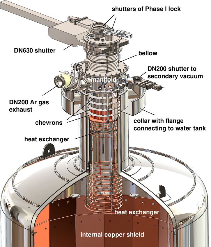
Contents

1 Introduction                                                          2

2 Design consideration for the cryostat - water tank system             4
  2.1 Shielding of external γ background                                4
  2.2 Safety considerations                                             6

3 Engineering description of cryostat                                   7
  3.1 Layout                                                            7
  3.2 Support of inner vessel                                           9
  3.3 Multilayer superinsulation                                       12
  3.4 Additional thermal insulation                                    12
  3.5 Production engineering                                           13
  3.6 The internal copper shield                                       14

4 Cryogenic infrastructure                                             15
  4.1 Cryogenic piping                                                 16
  4.2 Active cooling of LAr                                            16
  4.3 Vacuum system                                                    18
  4.4 Pressure regulation                                              18
  4.5 Safety devices against overpressure                              18
  4.6 Exhaust gas heater                                               19
  4.7 Slow control and graphical user interface                        19
  4.8 Water drainage                                                   20

5 Specific safety aspects                                              21
  5.1 Evaporation rates in case of failures                            21
  5.2 Critical operational parameters, alarms and mitigating actions   23

6 Commissioning and Performance                                        24
  6.1 Work at manufacturer                                             24
  6.2 Work in hall A of Lngs                                           25
  6.3 Performance and operating experience                             28

7 Conclusion                                                           29

A Heat transfer to LN2 and LAr in the pool boiling regime              30

B Timeline of the Gerda experiment                                     31

                                        –1–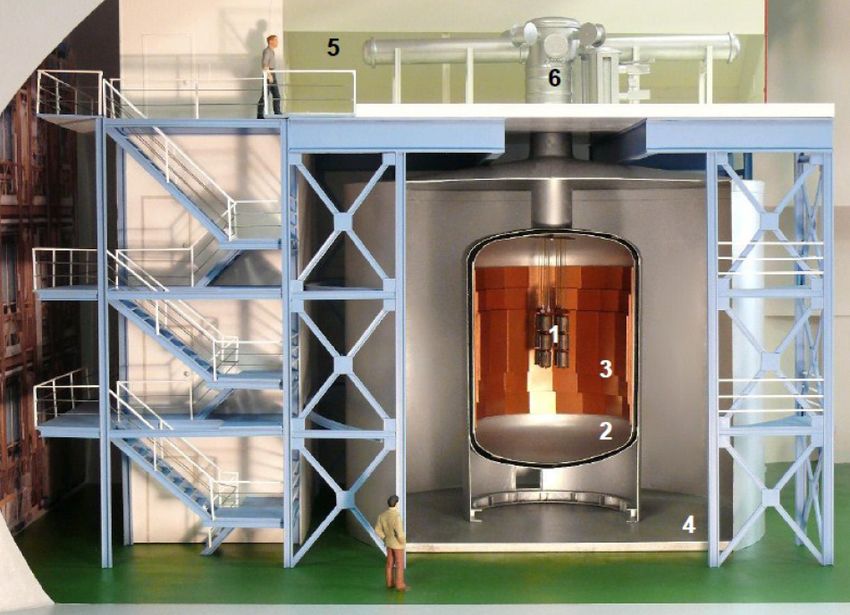
1   Introduction

The GERmanium Detector Array (Gerda) collaboration has terminated in February 2020
its search for neutrinoless double-beta (0νββ) decay of 76 Ge, 76 Ge→ 76 Se + 2e− [1–7].
Located in hall A of the Infn deep-underground Laboratori Nazionali del Gran Sasso
(Lngs), Italy, the experiment used germanium (Ge) diodes fabricated from high purity
Ge material enriched in the 76 Ge isotope fraction, simultaneously as source and detector.
The experimental signature for 0νββ decay is the observation of a peak in the energy
spectrum of the 2e− final state at the endpoint of the continuous energy spectrum of
the standard 2νββ double beta decay, 76 Ge→ 76 Se + 2e− + 2ν̄, which for 76 Ge is at the
transition energy Qββ = 2039 keV. The observation of 0νββ decay would have significant
implications on particle physics and cosmology: it would establish lepton number violation,
and the neutrino to be its own anti-particle (Majorana particle) supporting in this way
theoretical explanations of the baryon asymmetry in our universe [8].
     When the Gerda experiment was conceived in 2004 [9] previous experiments had
shown the detection of this hypothetical process to be extremely demanding. Almost 4
decades after the pioneering investigation into the 0νββ decay of 76 Ge by the Milano
group [10] its half-life limit had been improved by 5 orders of magnitude to about 1025
years. Major progress was due to the continuous reduction of the background index (BI)
which is the number of events at Qββ normalized to a 1 keV energy interval and exposure
(product of detector mass M and measurement time t). Another big improvement is due
to the use of enriched germanium since the signal-to-background ratio scales with the
enrichment fraction. However, none of the experiments was ‘background-free’, i.e., had an
expected background count < 1 at full exposure within an energy interval given by the
                                                                             √
energy resolution around Qββ . Hence their lifetime limit improved only as M · t and not
linearly in (M · t) as in the ‘background-free’ case. It was the goal of Gerda to realize for
the first time a ‘background-free’ experiment [9].
     Gerda achieved this goal in two steps. In Phase I (November 2011 to May 2013), it
improved the BI at Qββ to 10−2 cts/(keV·kg·yr), a factor of 10 lower than in previous Ge
experiments [2]. After an upgrade [3], Phase II (December 2015 to May 2018 and July
2018 to December 2019) yielded a further reduction of the BI by more than a factor of 10
[4–7]. A value well below 10−3 cts/(keV·kg·yr) had never been reached so far by any other
0νββ decay experiment if normalized by the energy resolution [7].
     Prerequisite for this success was the transition from the traditional compact lead-
copper shielding approach to the realization of a novel shielding concept. It emerged from
the proposal [11] to operate Ge detectors in ultra-pure liquid nitrogen (LN2) because of
the radiopurity of LN2 and its low Z. As we will discuss in the next section, LN2 was
replaced by liquid argon (LAr).
     Figure 1 shows the Gerda detector array of bare Ge diodes immersed in a large volume
(64 m3 ) of high purity (N5.0) LAr, which serves both as cooling and shielding medium. For
Phase II, the LAr was turned into an active veto system by adding instrumentation for the
readout of its scintillation light. The LAr is contained in a vacuum-insulated cryostat of

                                           –2–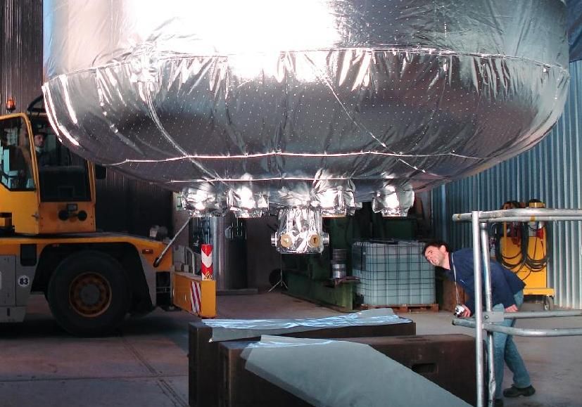
Figure 1. Artist’s view of the Gerda experiment in hall A of Lngs showing the (enlarged)
germanium detector array (1), the LAr cryostat (2) with internal copper shield (3), the surrounding
water tank (4), the clean room (5), and the lock (6) through which the Ge detectors are deployed
into the cryostat.

4.2 m diameter which itself is submerged in a large (650 m3 ) water tank of 10 m diameter.1
The purified water (> 0.17 MΩ·m) complements the shielding against the radiation from
the surrounding rock and concrete; it serves also as neutron shield and as the medium for
an active muon veto system [13].
     This installation comprises the first and so far the largest cryostat that is operated
underground within a large water tank. The same approach has been adopted in the
meantime by various experiments [14–17]. The new scenario of a cryostat immersed in
water required to construct a cryostat of extreme reliability. Because the surrounding water
represents a huge heat source, the failure/leakage of one of the two or both cryostat shells
could result in a huge evaporation or even a rapid phase transition of the cryogenic liquid
with potentially severe consequences. Special design features, extensive safety reviews and
a first measurement of the heat transfer in LAr contributed to a successful mitigation of the
associated risks. Since its first LAr fill in 2009 the cryostat has been operated without any
safety problem. Thus a major part of the Gerda experimental setup including cryostat
and water tank will be used for the upcoming Legend-200 experiment [18].
     This paper describes construction and performance of the cryostat including its cryo-
  1
      A similar setup with LN2 as cryoliquid had been proposed earlier [12], but has never been realized.

                                                   –3–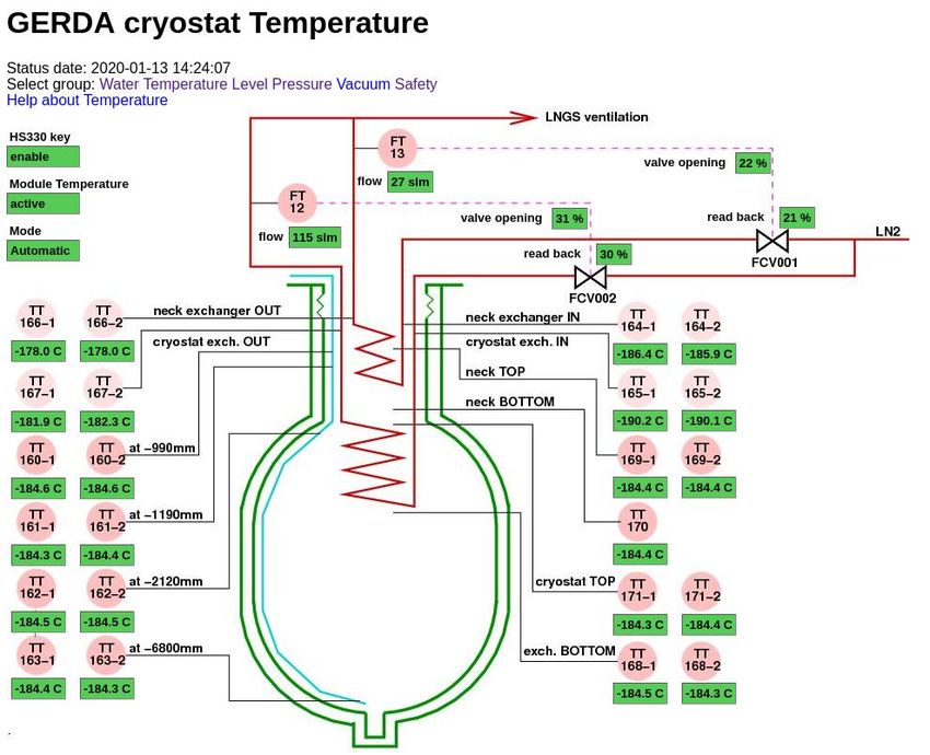
genic system. Section 2 discusses the specific design criteria of the water tank - cryostat
system and the associated safety aspects. Section 3 presents the engineering description
of the cryostat, section 4 the supporting cryogenic infrastructure. Section 5 addresses spe-
cial safety aspects of the operation of a cryostat in a water tank. Appendix A provides
supplementary material on heat transfer in the pool boiling regime. Section 6 summa-
rizes acceptance tests of the cryostat and its performance. Section 7 concludes the paper.
Appendix B shows the timeline of the Gerda experiment in more detail.

2     Design consideration for the cryostat - water tank system

Two major requirements determined the design of the cryostat and the surrounding water
tank, (i) reduction of the external γ radiation to the desired level, and (ii) outstanding
safe longterm operation. The first issue determines the size of cryostat and surrounding
water tank as well as the radio-purity of construction materials, the second - based on
rigorous risk analysis - the layout, construction procedures and certification of cryostat
and cryogenic infrastructure. Additional constraints include a minimum water thickness
of about 2 m to moderate neutrons efficiently and to provide a sufficiently large Cherenkov
medium for muon detection. The introduction of the water volume allows to use a smaller
volume of cryogenic liquid which is highly desirable from safety aspects. The diameter of
the cryostat is also limited by road transport to less than 4.5 m. Last but not least the
cryostat - water tank assembly has to fit into the allocated space in hall A, that is within
a diameter and height of 10 m, respectively. On top of that, about 2.5 m in height (4 m at
center) are left for cleanroom and lock through which the Ge detectors can be deployed
directly in the LAr contained in the cryostat (see Fig. 1 and Figs. 2 & 10 in [19]).

2.1    Shielding of external γ background
The external background consists of γ rays from the primordial decay chains, neutrons
and muons. As to the γ background at Qββ the predominant contribution is expected
to be due to the Compton tail of the 2.615 MeV γ line of the 208 Tl decay. In hall A of
LNGS the respective 2.615 MeV flux (surface activity) has been measured to be (0.031 ±
0.09)cts/(s·cm2 ) [20]. Assuming twice this value, measurements and Monte Carlo studies
have yielded for the BI of a shielded 2 kg Ge diode in hall A [19] the approximation of
BI = 2250 · X · exp(−X) cts/(keV·kg·yr) where X = Σi (ti µi ) > 5 is the sum of the products
of thickness ti and linear absorption coefficient µi of the various shielding materials i.
Table 1 lists absorption coefficients and activities of potential shielding materials. The
condition BI = 10−3 cts/(keV·kg·yr) yields X = 17.5. It implies that the surface activity
of hall A of 0.0625 Bq/cm2 has to be reduced by a factor exp(-17.5) to 1.6 nBq/cm2 which
yields t = 563 cm for LN2. Hence, to fit into hall A, a graded shield has to be considered
in which part of the LN2 is substituted by materials of larger absorption coefficients and
adequate radiopurity (see Table 1). Due to its high radiopurity water is a perfect substitute
for LN2.
     Figure 2 shows on the left a graded shield of water, copper of t = 3 cm thickness as
construction material for the cryostat, and LN2. The thickness of the water layer is chosen

                                           –4–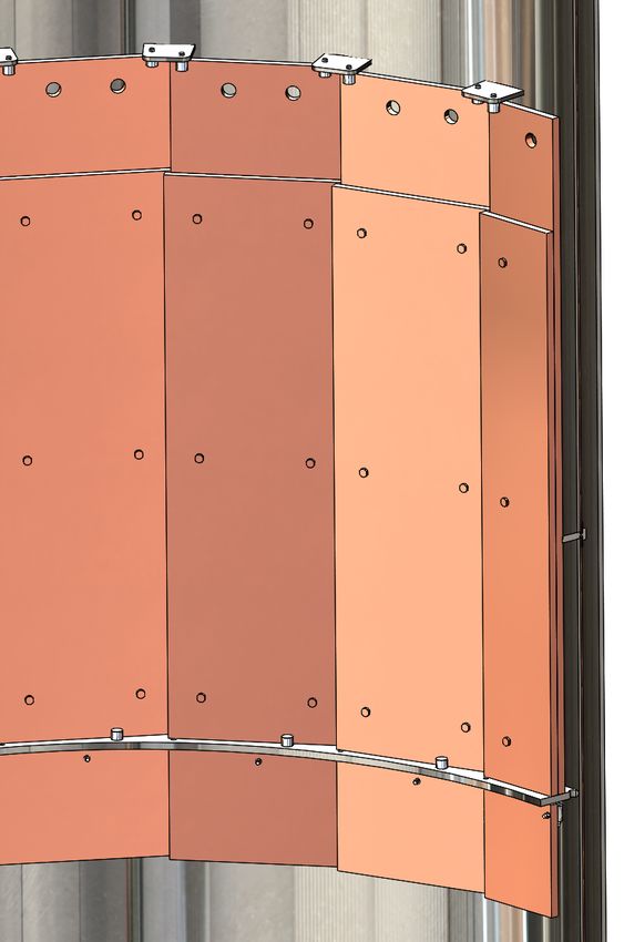
Table 1. Linear attenuation coefficients µ for 2.615 MeV γ rays in various materials including
liquid nitrogen (LN2) and liquid argon (LAr), the material’s assumed 228 Th mass activity Am as
well as the corresponding surface activity As for thickness t (see [19]). Note that, unexpectedly, it
was possible to procure stainless steel of significantly lower radioactivity (see Table 3).

                                                    materials                 µ              ρ        Am (228 Th)                                               As (208 Tl)
                                                                           [cm−1 ]      [g / cm3 ]     [µBq/kg]                                                [µBq/cm2 ]
                                                    LN2                    0.0311          0.81            *                                                         *
                                                    water                  0.0427           1.0            1                                                  t>1 m: 0.01
                                                    LAr                     0.050          1.39            *                                                         *
                                                    steel                   0.299          7.87          2·104                                               t=2 cm: 84.5
                                                    Cu                      0.338          8.96           25                                                 t=3 cm: 0.15
                                                                                                                                                            t>16 cm: 0.24
                                                    Pb                      0.484          11.35                                           30               t>10 cm: 0.25
                                                    * negligible

                                    −1   hall A : 0.0625 Bq / cm 2                                                                        −1    hall A : 0.0625 Bq / cm 2

                                    −2                                                                                                    −2
                                                                                                      log (surface activity / Bq/cm 2 )
log (surface activity / Bq/cm 2 )

                                                                                                                                                             262 cm water
                                    −3                303 cm water                                                                        −3

                                    −4                                                                                                    −4    steel

                                    −5                                                                                                    −5                                   17.4 cm copper

                                    −6                                                                                                    −6
                                         copper                                                                                                 copper
                                    −7                                                                                                    −7
                                                                                  168 cm LN2                                                                                          161 cm LN2
                                    −8                                                                                                    −8
                                         goal: 1.6 nBq / cm 2                                                                                   goal: 1.6 nBq / cm2
                                    −9                                                                                                    −9

                                               1           2          3            4        5                                                           1          2         3            4        5
                                                                     material thickness / m                                                                                 material thickness / m

Figure 2. Surface activities as a function of shielding thickness for the graded shields of the
Gerda baseline design of a copper cryostat (left) and the alternative of a stainless steel cryostat
with an internal copper shield (right). Thicknesses of water, copper and LN2 layers are indicated.

such to attenuate the external 2.615 MeV γ flux to the level of the copper surface activity.
To reduce the resulting low surface activity of 0.3 µBq/cm2 to the desired surface activity
of 1.6 nBq/cm2 , the LN2 layer has to be 168 cm thick. Taking the radial extension of the Ge
detector array into account, the inner diameter of the cryostat has to be 3.9 m to achieve the
desired BI. Preparations for the construction of an electron-beam welded superinsulated
cryostat of this size from low-radioactivity OFE copper (228 Th activity below 20 µBq/kg)
were well in progress when an unexpected increase of cost and safety concerns stopped the
project.
     The alternative design of a cryostat made from stainless steel (228 Th activity of 20

                                                                                                –5–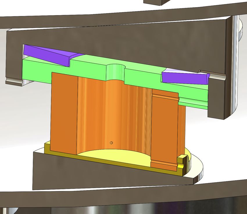
mBq/kg, typical for steel used in the Borexino experiment) would require a LN2 layer of
351 cm thickness that, together with the water layer, would not fit into hall A. Even the
equivalent thickness of an LAr layer of 217 cm would barely be acceptable and would result
in a total diameter that prohibits road transport. An additional copper layer of 17.4 cm
thickness will, however, reduce the surface activity of the steel to 0.24 µBq/cm2 so that a
LN2 layer of 161 cm thickness is needed (Fig. 2, r.h.s.). The thickness of the water shield
has to be chosen such that it suppresses the external 228 Th activity to a fraction of the steel
surface activity. For a 1% fraction the required water thickness is 262 cm. In this case, the
design of the cryostat has to accomodate also the additional weight of the internal copper
shield which is about 50 tons.
      The above estimates have been refined by detailed Geant4 simulations with a cryostat
geometry very close to that actually built [21]. The neck through which the detector array
is deployed has no water shielding which is ignored in above estimates. The full simulation
showed however that the γ flux through the neck is dominating the background for LN2
filling. This result together with the advantage of a reduced Cu thickness for LAr and
the additional background suppression by the detection of argon scintillation light led to
the decision to drop the LN2 option. The final solution is a double-walled superinsulated
stainless steel cryostat of cylindrical shape with an internal copper shield and a 172 cm long
neck (see next section). With a LAr fill the surrounding 228 Th radioactivity is expected to
contribute 8 · 10−6 cts/(keV·kg·yr) to the BI [21].

2.2   Safety considerations
The storage of a large amount of cryoliquid underground implies the risk to create large
volumes of N2 or Ar gas in case of leakage which themselves are not poisonous but might
cause suffocation of people working in the underground area. The standard mitigation
of this risk is monitoring the O2 content in air, and increased ventilation in case of too
low O2 concentration. The operation of a cryostat in water constitutes an enhanced risk
since leakage would imply here both the possibility of a fast evaporation of the cryoliquid
or the mixing of water and LN2/LAr resulting in an even faster possibly explosive phase
transition. Hence it is obvious that the risk of leakage should be minimized, as much as
possible, by design and construction. These measures are summarized below while the
mitigation of leakage and the safety aspects of the whole system are discussed in section 5.
     The design and production of the cryostat have been done according to the European
Pressure Equipment Directive (PED 97/23/EC) for a nominal overpressure of 1.5·105 Pa,
even though it is operated at 0.3·105 Pa and hence below the limit of 0.5·105 Pa above
which this code applies. An additional safety margin is achieved by the increase of 3 mm
of the wall thickness of the inner (cold) vessel which allows its evacuation. Evacuation is
needed for He leak tests, Rn emanation measurements and, before the filling with LAr,
the removal of contaminations. No ports below the filling levels of cryoliquid and water
have been implemented. Standard cryostats have ports e.g. at the bottom for emptying
or for measuring the hydrostatic pressure which are known [22, 23] to increase the risk
of leakage. The entire cryostat is rotational symmetric so that local stress is minimized.
Where this symmetry is broken locally, i.e. at the location of the support and centering

                                             –6–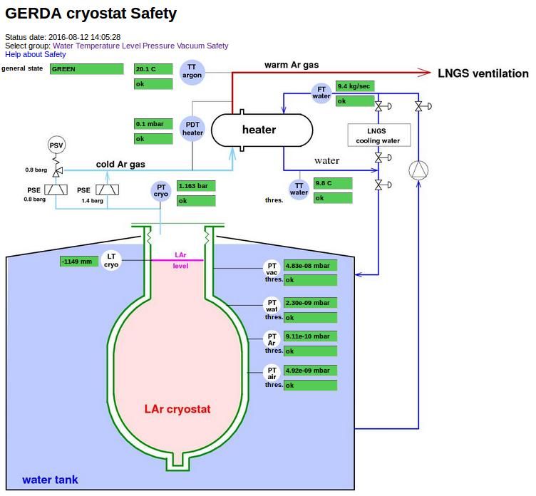
pads, the wall thickness is enlarged to lower absolute stress values. Different from standard
cryostats where the inner cold vessel is hung at the neck, it is resting here on pads at the
bottom. This reduces stress peaks from loads due to earthquakes. In fact, the cryostat is
designed to withstand loads from the ‘Maximum Credible Earthquake’ [24] of up to 0.6 g
horizontally and vertically without damage. The use of highly ductile stainless steel as
exclusive construction material enforces the ‘leak-before-break’ concept [25]. The choice of
a stainless steel alloy with Mo and Ti additions, 1.4571 (X6CrNiMoTi17-12-2), warrants
improved corrosion resistance. The inspections or certifications specified by the PED guar-
antee a high production quality that is enhanced by the special requirement of 100% X-ray
inspection of the accessible welds.
3 Engineering description of cryostat
3.1 Layout
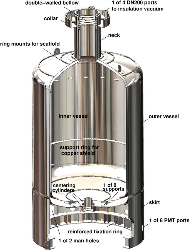
Views of the cross section and a solid model of the cryostat2 are shown in Fig. 3 and Fig. 4;
its main characteristics are listed in Table 2.
The cryostat3 consists of two coaxial vessels that are built from torospherical heads4 of
3976 mm and 4160 mm inner diameter and corresponding cylindrical shells of 3900 mm and
4149 mm height. Each vessel has a cylindrical neck of 789 mm and 964 mm inner diameter,
respectively, and of about 1.7 m height; on top they are connected to each other by a flange
which will hold a full metal seal. Since the inner container rests via pads on the bottom
of the outer vessel (see below), its shrinkage of about 2 cm when cooled down from 300 K
to 77(88) K is compensated by a double-walled stainless steel expansion joint5 in its neck.
It is kept centered by six Torlon® spacers within the neck and at the bottom. In case of
earthquake the largest stress will occur at the transition between neck and upper vessel
head, and thus this part is reinforced by an additional stiffening ring.
The volume between inner and outer vessel, about 8 m3 , will hold the vacuum multi-
layer insulation. Access to this volume is provided by four CF200 flanges at the very top of
the neck which are used as connections to the pumping station, safety and pressure relieve
valves and manometers (see Fig. 4). The flanges are separated from the water tank by a
circular collar around the neck that represents also the support ring for the flexible fabric
which closes the gap between cryostat and water tank.
The inner (cold) vessel is designed for vacuum and 1.5·105 Pa overpressure (i.e. 2.5·105 Pa
absolute pressure) together with the hydrostatic pressure of LAr. The outer vessel is de-
signed for 1.0·105 Pa overpressure and vacuum together with an external pressure of a
water column of 7.8 m (-1.78·105 Pa external overpressure). The construction material,
type 1.4571 stainless steel, purchased in various batches of varying thickness for vessel
2
An alternative layout based on an available standard cryostat design has been provided by PJSC
“Cryogenmash” 143907, Balashikha, Moscow Region, Russia.
3
Fabricated by Simic S.p.A., I-12072 Camerana, Italy.
4
Produced by ANTONIUS, NL-6051 Al Maasbracht, The Netherlands.
5
Delivered by HKS Unternehmensgruppe, D-18057 Rostock, Germany.
–7–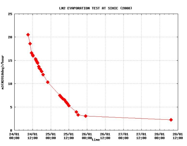
Table 2. Characteristics of cryostat.

  Materials, Th-228 radiopurity
  vessels, compensators                          1.4571* ( 25 ton )        0.1-5 mBq/kg
  multilayer insulation                        alu. polyester (15 kg)
Figure 3. Cross section of the Gerda cryostat. Labelled arrows and lines refer to (not shown)
further sectional views and to the parts list, respectively.

3.2   Support of inner vessel
The inner vessel rests on 8 support pads. The respective horizontal counter adaptors are
welded equally spaced at the bottom vessel heads of inner and outer vessels on a circle of
1600 mm diameter and milled afterwards for good flatness. The inner vessel is kept centered
by six Torlon® spacers within the neck and at the bottom. Fig. 5 shows a schematic of one

                                           –9–
Figure 4. CAD drawing of the steel parts of the Gerda cryostat. support pad. The usual material for support pads, glass fiber reinforced epoxy, has been replaced by tubes (Ø183(100) × H 100 mm) made from Torlon® 4203/4503. At 77 (296) K this polyamide-imide (PAI) material exhibits a better radiopurity of
Table 3. Size and activity (in mBq/kg) of 1.4571 stainless steel sheet material used for vessel
production. Full screening information is provided for each sample in [26].

                Outer vessel     Sample       L x H x t [mm3 ]            228 Th     60 Co

                top head            D3       4800    x   2500   x   12    1 ± 0.4      15
                                    D3       4800    x   2500   x   12    1 ± 0.4      15
                wall                G5       6000    x   2000   x   20   1.5 ± 0.2     16
                                    G1       1900    x   2000   x   20     < 0.2       46
                                    D6       6000    x   2000   x   20     < 0.8       17
                                    G1       6000    x   2500   x   20     < 0.2       46
                                    G2       8000    x   2500   x   20     < 0.1       14
                bottom head         D1       4800    x   2500   x   20    3.4 ± 1       7
                                    D1       4800    x   2500   x   20    3.4 ± 1       7
                Inner vessel
                top head            D2       4600    x   2500   x   12    < 1.7        14
                                    D2       4600    x   2500   x   12    < 1.7        14
                wall                G3      12900    x   2000   x   12    < 0.4        14
                                    G3      12900    x   2000   x   12    < 0.4        14
                bottom head         D5       4600    x   2500   x   15    < 1.1        17
                                    D4       4600    x   2500   x   15    < 1.8        15

                                                                            1

                                                                            2

                                                                    3

                                                                4

                                                 6
                                5
                                                                            7

Figure 5. Close up of one of the eight supports on the bottom of the inner vessel consisting of the
cage (2) for the Belleville spring (3) welded to the bottom vessel head of the inner vessel (1), the
Torlon® cylinder (4) for thermal insulation, and the countersurface (5) at the bottom vessel head
(7) of the outer vessel. The bronze shoe (6) for improved sliding has not been implemented.

of 282 (244) MPa [28]). Belleville springs6 made from Inconel X718 with spring constants
  6
      Delivered by MUBEA, D-57567 Daaden, Germany.

                                              – 11 –
of 58 kN/mm are used to compensate small differences of the gaps between the bearings
so that all pads will carry about equal load once the cryostat is filled (see sect. 6.1). Each
pad is fixed at the cold inner vessel. During cool down, the warm end of the pad will move
by about 3 mm.
3.3 Multilayer superinsulation
The complete outer surface of the inner vessel is covered up to the compensator with
multilayer superinsulation (MLI) consisting out of 2x 15 layers.7 The nominal thickness of
a 15 layers MLI blanket is 3 to 5 mm. The inner and outer layers of a blanket are made
from TERIL 53, a 6 µm thick polyester film aluminized on both sides with a thickness of
400 Å, reinforced with a polyester net. The other 13 layers consist of IR 305, i.e. a 6 µm
thick perforated polyester film aluminized on both sides with a thickness of 400 Å, and a
polyester tulle with an approximate weight of 5 g/m2 . The perforation diameter is 2 mm,
and the distance between perforations is 56 mm. Fig. 6 shows the bottom part of the
inner vessel including the Torlon® pads with the MLI assembly. Table 4 shows that the 8
Figure 6. Detail of the MLI arrangement at the bottom of the inner vessel showing the coverage
of support and centering pads.
Torlon® pads and the superinsulation contribute similarly to the expected thermal loss of
about 250 W while the neck - due to its thin walled (2x 0.8 mm thick) bellow - contributes
10% only.
3.4 Additional thermal insulation
Inner and outer vessel carry thermal shields which keep the Ar evaporation rate below
104 m3 /h (STP) for the case of a water/LAr leak in the outer/inner vessel (see section 5).
7
Delivered and mounted by Jehier, F-49120 Chemille, France.
– 12 –Table 4. Contribution of various components to thermal losses.
Component area, height thermal conductivity thermal loss
neck, bellow 0.0041 m2 , 0.44 m 15 W/(m·K) 30 W
Torlon® pads 8x0.041 m2 , 0.1 m 0.18 W/(m·K) 128 W
superinsulation 100 m2 , - 0.5 W/m2 100 W*
* including safety factor of 2
The outside surface of the vertical shell of the inner vessel is covered below the MLI
with a 6 mm thick polycarbonate (Makrolon® ). This material has been chosen since its
properties are adequate for the use at cryogenic temperatures, and since it is rigid and has
a relatively low thermal conduction coefficient of 0.2 W/(m·K). Less favourable features are
its relatively large linear thermal expansion coefficient (65·10−6 /K at room temperature)
as well as its water absorption of 0.12% at 23 ◦ C and 50% relative humidity.
Similarly, the outer surface of the vertical shell of the outer vessel as well as its bottom
are covered with 6 mm thick extruded polystyorol foam8 which is hermetically covered
by a multilayer polyester foil9 with > 98 % specular reflectance that serves in addition as
reflector for the Cherenkov radiation in the water tank.
The thickness of the polycarbonate and the polystyrol layers have been deduced from
test measurements of the heat transfer in the pool boiling regime for the interface liquid
nitrogen - stainless steel - water (see section 5).
3.5 Production engineering
The production process was subject to the AD 2000 code and PED 97/23/EG and con-
trolled by representatives of a notified body (TÜV Nord, Germany). We summarize here
a few non-standard additional features for further improvement of the cryostat’s reliability
and performance.
The production of the cryostat and the MLI installation have been carried out in a
‘gray’ area which was separated from the standard carbon steel production sites. All welds
were done by TIG welding using exclusively thorium-free TIG-welding electrodes. For the
welding filler, material of less than 5 mBq/kg 228 Th radioactivity has been selected. Before
production, the effectiveness of weld preparation and procedures even in case of thermal
shocks was verified with two 500 mm long 1.4571 sheets that were welded together and
subsequently immersed into liquid nitrogen. The chosen welding procedure yielded for the
low temperature notch impact energy the value of 120 J that is almost 4 times higher than
required by AD2000. All welds have been passivated to avoid corrosion. The cleaning
procedure for all inner and outer surfaces included removal of oil and grease, pickling and
passivation, rinsing with de-ionized water and subsequent drying. Ferroxyl tests did not
reveal any ferrite inclusions on the surfaces.
8
Jackodur KF300 FTD by JACKON Insulation GmbH, D-33803 Steinhagen, Germany.
9
VM2000 by 3MTM Deutschland GmbH, D-41453 Neuss, Germany.
– 13 –All accessible welds of the inner and outer container of the cryostat have been 100%
X-ray tested. Where such a test was not possible like at the final orbital weld an ultrasonic
test was done.
3.6 The internal copper shield
The screening of the stainless steel material used for the cryostat yielded an unexpected low
radioactivity [26] that allowed to reduce the amount of the internal copper shield from the
envisaged 48 tons to less than 16 tons. Its thickness and profile have been determined by
Monte Carlo calculations [21]. The profile is symmetric w.r.t. the midplane, the thickness
is 6 cm up to the height of 1 m, and continues from there with 3 cm thickness up to 1.4 m
(see Fig. 7). The shield is assembled from 20 overlapping segments which fit through the
cryostat’s neck. Each segment consists of three 3 cm thick and 61.5 cm wide copper plates
of 40, 200 and 240 cm length, respectively. The two longer plates are screwed together and
rest on a support ring within the cryostat. The short plate is attached below.
holes for lifting
0.4m
1m
screws
1m
0.4m
support ring
Figure 7. Three (and a half) of 20 segments of the internal copper shield as mounted in the
cryostat.
The copper plates have been rolled10 in spring 2007 from freshly produced OFPR
copper.11 After rolling, the plates were warmed up to 50◦ C, pickled in >15% sulfuric
acid, and, immediately afterwards, rinsed with de-ionized water. The individual segments
were vacuum-packaged after assembly, and an additional plastic wrap protected them for
10
By CSN Schreiber, D-57290 Neunkirchen, Germany.
11
By Norddeutsche Affinerie, now Aurubis AG, D-20539 Hamburg, Germany.
– 14 –Figure 8. Close up of the top of the cryostat including neck, manifold and interface to the lock.
For Gerda Phase II, the two shutters of the Phase I lock above the DN 630 shutter have been
removed.
transportation to Lngs where they are kept underground since June 2007 to prevent further
cosmic activation.
4 Cryogenic infrastructure
The cryogenic infrastructure has to ensure a stable and safe operation of the cryostat.
Since the neck provides the only access to the interior of the cryostat, a manifold on top
of the neck carries the flanges for all lines that penetrate into the cold volume including
filling tube, gas exhaust tube, tubes for active cooling, and feedthroughs for the cryostat
instrumentation (see Fig. 8). The manifold is connected with a bellow to a DN630 shutter12
which is located at the floor of the clean room. The bellow allows for 25 mm lateral
movements of the clean room with respect to the cryostat in case of an earth quake.
The shutter separates the cryostat from the lock. It is closed while the lock is open for
12
Gate valve, Series 19, by VAT Deutschland, D-01109 Dresden, Germany.
– 15 –germanium detector installation. All valves13 have metalic sealing against atmosphere.
The control of most pneumatic valves and readout of sensors is done with a programmable
logic controller (PLC) Simatic S714 that is dedicated to the control and monitoring of
the cryogenic infrastructure. The power for the entire infrastructure is connected to an
uninterruptible power supply backed by a generator which is either driven by normal electric
power or a battery.
The various parts of the cryogenic infrastructure are discussed below.
4.1 Cryogenic piping
The first filling of the cryostat with LAr and the optional refilling during the standard
operation is done from a selected storage tank (radon emanation about 5 mBq, operated
at 3·105 Pa) which is located in the TIR tunnel, about 30 m away from the cryostat. At the
same location are also 2 storage tanks for LN2. One (4.0-4.5·105 Pa) for LN2 extraction
at the nominal pressure of 3.2·105 Pa relative to atmospheric pressure for the LAr active
cooling and one for gaseous nitrogen at a higher pressure of 8·105 Pa which is used for
flushing of glove boxes and the operation of pneumatic valves. For the pipe15 from the
storage tank to the cryostat a triaxial pipe was chosen: the LAr pipe is the inner pipe
(DN 25) at a LAr boiling temperature of ≈99 K, the LN2 flows outside the LAr pipe in a
DN 50 pipe at a lower temperature of ≈91.3 K and the space between the DN 50 and the
outer third pipe (DN 100) holds the vacuum insulation. The lower LN2 temperature allows
to subcool LAr without freezing it (84 K) and hence to reduce argon flash gas losses.
As a safety feature the pressure in the LN2 pipe is used to operate pneumatic valves at
the outlets of the storage tanks. If due to a rupture of the pipe, for example, the pressure
is too low the valves close and the spilling of LN2 and/or LAr will be stopped.
The LAr passes optionally through a charcoal filter to retain radon (about 1 kg mass)
which is cooled with LN2 to about 86 K. Afterwards two PTFE filters16 with 50 nm pore
size and 10 inch length are added in series to retain any particles.
The filters together with all valves for LN2 and LAr are in a vacuum insulated box
called ‘valve box’.
Before the LN2 pipe enters the valve box a phase separator called ‘keep cold device’
allows to remove gaseous nitrogen.
4.2 Active cooling of LAr
Inside the cryostat are two LN2/LAr heat exchangers in form of spirals made from 18 mm
x 1 mm copper pipes: one at the liquid/gas surface and one in the main volume of the
cryostat (see Fig. 8). The diameter of the spirals is about 760 mm.
13
Cryogenic valves by Flowserve Kämmer, D-25524 Itzehoe, Germany; for gases manual valves series BG
by Swagelok, Solon, Ohio 44139, USA.
14
Simatic S7 by Siemens, D-80333 München, Germany.
15
Cryogenic piping, ‘valve box’ and ‘keep cold device’ produced and installed by DEMACO, NL-1723 ZG
Noord-Scharwoude, The Netherlands.
16
Fluorogard CTFZ01TPE by Entegris Eastern and Central Europe, D-01109 Dresden, Germany.
– 16 –The pressure at the gas outlet of the heat exchanger is about 1.2·105 Pa absolute which
corresponds to a LN2 boiling temperature of 79.6 K. The cryostat pressure is also regulated
to 1.2·105 Pa absolute which corresponds to an LAr boiling temperature of 89.0 K at the
liquid surface. Due to the hydrostatic pressure the boiling point increases deeper inside
the cryostat. The LAr is cooled to about 88.8 K.
Figure 9. Distribution of temperatures within the LAr cryostat with powered Ge detector array.
There are in total 29 PT-100 sensors inside the cryostat to measure the LN2 tempera-
tures at the heat exchanger inlets and outlets as well as the LAr temperatures at different
heights. It turns out (see Fig. 9) that the LAr temperatures are within the precision of
our measurement (0.1◦ C) the same everywhere except at the surface where they can be
adjusted to be a few tenths of a degree higher. The interpretation is that convective cur-
rents lead to a strong mixing effect and hence to a homogeneous temperature. Also: no
argon ice formation at the heat exchangers is observed despite the fact that the LN2 boiling
temperature is about 3 degrees below the freezing point.
The LN2 flow regulating valves are inside the valve box. The pressure at the inlet is
3.5-4·105 Pa absolute. After the valves the pressure is only 1.2·105 Pa absolute. Because of
the pressure drop a gas/liquid mixture passes through the heat exchangers. The diameter
of the pipe from the valve box to the cryostat was chosen to be only 8 mm and the pipe
is always inclining upwards to ensure a large flow speed such that the gas/liquid mixture
does not separate. This concept [29] is supposed to reduce flow variations in the cooling
and hence microphonics although the measured gas flow still shows variations by ±20% on
a time scale of minutes. Through the bottom heat exchanger the flow is adjusted to on
average 120 slm (liters of gas per minute at standard pressure and temperature) and for
– 17 –the other one to 15 slm.
4.3 Vacuum system
The insulation vacuum is pumped by a 600 `/s turbomolecular pump17 with mechanical
rotor suspension that was backed at full gas load by a 40 m3 /h , and later by a 8.5 m3 /h
rotary vane pump. The pump is mounted with a DN160/200CF adaptor onto a DN200CF
shutter18 that is attached to one of the four CF200 ports (see Fig. 8). After some years
of operation the turbomolecular pump was replaced by the smaller 150 `/s model. The
turbo pump is running continously. If momentarily switched off, the pressure increases at
5·10−7 hPa·`/sec.
The pressure is monitored redundantly and read out by the PLC. If it is too high or if,
e.g. the turbo pump signals an error, the shutter between cryostat and turbo pump will be
closed. The vacuum is also monitored by a residual gas analyzer.19 The partial pressures
for water, argon and nitrogen are read out and can be used to diagnose a problem in case
the total pressure rises unexpectedly.
Another one of the four CF200 ports carries the overpressure protection device for the
insulation vacuum volume. It is realized by a DN 100 disk with a rubber O-ring seal which
is tightened by the air pressure.
4.4 Pressure regulation
The Ar gas pressure in the cryostat is one of the critical parameters. It is regulated by two
intelligent pressure transmitters that include a PID (proportional, integral, differential)
controller with a mean time between failure (MTBF) of 244 years.20 Each of the analog
output signals is directly used to control a DN 50 valve21 (kvs = 40). These pressure
regulation circuits operate therefore independently of the PLC which has a lower MTBF
rating.
In case of power failure the above mentioned valves are normally closed. Therefore a
DN10 valve22 with a smaller opening (kvs = 1.6) was added. The discharge rate through
this ‘normally open’ valve is large enough to keep the pressure below 1.2·105 Pa absolute
for at least one week in case of loss of power or loss of nitrogen for the actuator.
4.5 Safety devices against overpressure
The cryostat is equipped redundantly with a safety valve and a rupture disk. The safety
valve23 has a trigger point of 0.85·105 Pa relative to atmospheric pressure and a flow area
of 7500 mm2 . Since the safety valve is not leak tight against the atmosphere, a DN150
rupture disk24 with a trigger point of 0.8·105 Pa relative to atmospheric pressure has been
17
Turbovac 600C by Oerlikon Leybold Vacuum, D-50968 Köln, Germany.
18
UHV gate valve, series 10, by VAT Deutschland, D- 01109 Dresden, Germany.
19
Model PPM100 Partial Pressure Monitor by Stanford Research Systems.
20
Model LD301 by Smar Europe B.V., D-55545 Kreuznach, Germany.
21
Type 2415 P3 from Flowserve Kämmer, D-45145 Essen, Germany.
22
Type 241 H3 from Flowserve Kämmer, D-45145 Essen, Germany.
23
Type 411 from LESER GmbH & Co. KG, D-20537 Hamburg.
24
Type CF160-UKB-LS-FL 6 from REMBE GmbH Safety + Control, D-59929 Brilon.
– 18 –added in front. This disk is welded into its stainless steel holder and has ConFlat flange
DN160 connections.
The same type is used as rupture disk, here with a maximum trigger point of 1.4·105 Pa
relative to atmospheric pressure. To signal its rupture or damage a signal rupture disk is
added afterwards.
Both devices are large enough to cope with a maximum discharge rate of 4.5 kg/s of
argon gas.
4.6 Exhaust gas heater
The argon exhaust gas is passed to the Lngs ventilation system that pushes it through
a pipe in the highway tunnel to the outside. In case of a faulty operation of the cryostat
the cold argon gas would freeze the water vapor present in the pipe and the fans could
stop working. Both scenarios would result in a collaps of the system. The argon gas must
therefore be warmed up above 0◦ C before it is discharged to the LNGS ventilation system.
A water/gas heat exchanger25 is installed for this purpose. The exhaust gas from the safety
valve and rupture disk of the cryostat, from the safety disk of the insulation vacuum and
all other valves is collected into a DN200 pipe which is connected to the inlet of the heat
exchanger. The gas then passes through a bundle of 121 pipes with 18 mm inner diameter.
Outside the pipes is water to heat up the cold gas. The outlet of the heat exchanger is
directly connected to the ventilation system of Lngs. A bypass between inlet and outlet
is added with a burst disk to avoid overpressure in case the heat exchanger is blocked for
some reason.
The water is normally the cooling water of Lngs but as a backup a pump is installed
to pump the water from the water tank through the heat exchanger.
4.7 Slow control and graphical user interface
Apart from the redundant high-reliability pressure regulation, all sensors, valves and pumps
of the cryogenic infrastructure are monitored and controlled continously by the Simatic S7
PLC. The PLC evaluates the safety status of the cryogenic system, and automatically
triggers appropriate actions if needed. The safety relevant status information is shared
with the Lngs safety network via MODBUS and hardwired by a cable transmitting the
relevant status bits. Using CGI scripts, a Linux web server reads or writes data from or to
the PLC via TCP/IP access, acting both as DBclient for the general Gerda slow control
system [30] and the Hypertext Transfer Protocol (HTTP). Thus performance and status
of the Gerda cryogenic system can be examined and, in part, controlled remotely. Fig. 10
shows for example the safety summary page where all critical operation parameters for the
cryostat and supporting infrastructure are displayed and color-coded (see subsection 5.2).
Other pages show the status of the water system, the temperature distribution (see Fig. 9),
the fill level, and the values of the pressures measured for cryostat and insulation vacuum.
25
Model C300 1708-2PASS by FUNKE Wärmetauscher Apparatebau GmbH, D-31028 Gronau, Germany.
– 19 –Figure 10. Safety status of the GERDA experiment as inquired at 14:05 on August 8, 2016 via
the web interface. The values of all critical operation parameters are within the specifications for
standard operation (see subsection 5.2).
4.8 Water drainage
The fast drainage of the water is important in case of an emergency. Therefore the PLC
that monitors the cryostat is also controlling the drainage valves of the water tank. There
are three different lines: (i) the main DN250 pipe below the tunnel road with an allowed
maximum flow rate of 80 ` / s, (ii) a DN90 line ( 18 ` / s) to 100 m3 storage containers in hall
A, the so-called ‘GNO pits’, and (iii) a DN80 pipe (20 ` / s) which is part of the emergency
water supply system for the Gerda exhaust heater leading also to the GNO pits. The
PLC controls the valves to these lines as well as the flow rate in the main DN250 pipe via a
butterfly valve so that a constant standard flow rate of 20 ` / s or, in emergency, a maxium
flow rate of ≤80 ` / s are maintained independent of the hydrostatic pressure in the water
tank.
A test of the fully automated drainage procedure in 2010 showed that measured and
predicted drainage times are in very good agreement with each other, and that in case of
emergency the water tank can be emptied in less than 2 hours.
– 20 –5 Specific safety aspects
5.1 Evaporation rates in case of failures
Compared to standard cryogenic installations the Gerda cryostat-water-tank system ex-
hibits the additional risk that the separation between water and the cryogenic container is
broken resulting in potentially huge gas exhaust rates.
In the worst case scenario, i.e. the simultaneous rupture of inner and outer container
wall, the mixing of LAr and water could lead to a rapid phase transition. External consul-
tants26 have evaluated this risk and found it to be extremely unlikely, < 10−8 ev/yr, due
to (i) the mutual independence of the two stainless steel cryogenic vessels that are built
according to established construction codes, (ii) the irrelevance of corrosion related to the
galvanic interaction between copper shield and the austenitic 1.4571 stainless steel, (iii)
the earthquake tolerance of 0.6 g, (iv) the redundant monitoring of the critical operational
parameters (COPs, see below sect. 5.2), and last but not least, (v) the fulfillment of the
‘leak-before-break’ principle.
In case of a small leak in one of the two vessels the insulation vacuum would be lost.
A compilation of the thermal conductivity of superinsulation in dependence of the gas
pressure shows [31] that in the most conservative estimate a superinsulation with a heat
flux of 1 W/m2 between 77 and 300 K is degraded by a factor of 1000 in case of a complete
loss of insulation vacuum. Hence, with the cryostat’s surface of about 100 m2 and 97 tons
of LAr it will take about 44 hours until all LAr has been evaporated. The resulting gas
flow (20 C◦ ) of about 1340 m3 /h is small compared to the limit of 10000 m3 /h set by Lngs.
A major leak in the outer vessels would destroy not only the insulation vacuum but
enable the surrounding water to enter the space between inner and outer vessel. Water
with its high specific heat capacity of 4.19 kJ/(kg·K) represents an efficient heater for the
cryogenic liquid. A drop of less than 6◦ C in temperature of the 590 m3 stored water
is enough to evaporate the 64 m3 of LAr contained in the cryostat. An estimate of the
resulting gas flow is difficult lacking detailed knowledge of the involved heat transfer. The
heat transfer in an unsteady state involving phase changes has been discussed by various
authors, see e.g. [32, 33] but the application of the reported results is not obvious. Hence,
experimental model studies have been performed in order to arrive at a more quantitative
understanding of the evaporation rates in a worst case scenario for a water-cryostat system
(see Appendix A).
Using the deduced maximum heat transfer coefficient of 27 kW/m2 for LAr, the rate of
exhaust gas for the Gerda configuration with a total mass of 90 tons of LAr is predicted
for the worst case scenario, that is the sudden removal of the outer container such that
the inner cryogenic container is immediately exposed to the surrounding water. The black
circles in Fig. 11 show that at the assumed heat transfer coefficient of 27 kW/m2 the
total mass is evaporated after less than 5 h, and that the corresponding gas exhaust rate
peaks at almost 30000 m3 /h which is not acceptable. However, if the heat transfer through
the cylindrical wall is limited to 5 kW/m2 (red curves in Fig. 11) it will take about 9
26
Nier Ingegneria S.p.A., I-40013 Castel Maggiore (Bo), Italy.
– 21 –Figure 11. Results of model calculations for the argon mass loss (top) and evaporation rate
(bottom) in case of an emergency with a heat transfer coefficient of 27 kW/m2 (black open circles)
and a reduction to 5 kW/m2 in the cyclindrical part (red filled circles).
– 22 –hours to evaporate all LAr, and the gas exhaust rate will stay well below the limit of
10000 m3 /hr. The limitation of heat transfer can be achieved by covering the wall of the
inner vessel with about 5 to 10 mm thick plastic material of thermal conductivity between
0.1 and 0.25 W/(m·K). This requirement is well fulfilled by polycarbonat which exhibits
also the required vacuum compatibility and low temperature properties. The amount of
LAr contained in the volume above the covered cylindrical wall in the vessel head and neck
is about 3 m3 . Its evaporation would take less than 5 minutes in which time the exhaust
rate could reach 13000 m3 /h.
For a leak in the inner vessel similar considerations apply. The maximum gas flow might
be lower since overpressure inside the insulation vacuum volume might inhibit further flow
of the cryoliquid. However, other than in case of a leak in the outer shell, the prevailing
amount of the gas cannot escape through the cryostat’s neck but has to pass through the
DN100 overpressure release disk mounted on one of the CF200 ports. Thus the insulation
volume is also equipped with an overpressure safety device. The thermal shield does not
need to be vacuum compatible. Hence on the outside of the outer vessel lightweighted
6 mm thick extruded polystyrol (Jackodur) panels (and a VM2000 foil layer for the muon
veto) are used.
5.2 Critical operational parameters, alarms and mitigating actions
Table 5 provides a list of the three COPs identified in the risk analysis [34], (i) pressure in
the cryogenic volume of the cryostat, (ii) pressure in the insulation volume, and (iii) the
LAr fill level27 in the cryostat’s neck. Seven additional COPs allow superior diagnostics
of possible failures and the suppression of false alarms: (iv-vi) partial pressures of ’air’,
argon and water in the insulation vacuum, and four parameters of the water-cooled Ar gas
heater, (vii) differential pressure between entrance and exit for the Ar gas being directly
proportional to the square of the mass flow through the heater, (viii) temperature of the
exhaust gas at its exit, (ix) flow rate of water through heater, and (x) temperature of water
at the exit of heat exchanger. All parameters are deduced from at least two redundant
sensors except the residual gas pressures and the cooling water parameters. The PLC
continously evaluates the COPs, and determines the Gerda safety status in terms of
familiar color codes. If some COPs deviate sigificantly from the foreseen range (see Table 5),
it prompts automatically appropriate alarms and actions to mitigate the associated risks.
‘Green’ indicates standard operation within the specifications. ‘Yellow’ summarizes all
events with no or marginal impact on the safety in hall A indicating the need for corrective
maintenance. A typical event for this class would be a loss of insulation vacuum due to
an air leak. ‘Orange’ designates events with little immediate impact on the safety of work
in hall A but which might develop to an event of category ‘red’. A typical event would
be a microscopic leak in one of the cryostat’s walls. ‘Red’ designates the events of highest
impact to the complete underground laboratory, e.g. a macrosopic leak in one cryostat
wall with the resulting high evaporation rate. The actions for the ‘orange’ levels 1-3 (see
27
This parameter turned out to be irrelevant since an insignificant amount of LAr was lost only during
Ge detector immersion.
– 23 –Table 5. Critical operational parameters (COPs) and thresholds for mitigating actions. The
threshold index code designates the category of the event which has triggered the respective alarm.
COP thresholds code
green yellow orange red
Cryostat
p [105 Paabsolute ] (i) < 1.5 > 1.5
fill level [mm] (ii) < −760 > −760
insulation vacuum
p [hPa] (iii) < 10−4 [10−4 , 0.1] o3 >0.1 r1
pres,air [hPa] (iv) < 10−4 > 10−4
pres,Ar [hPa] (v) < 10−4 > 10−4 o2
pres,water [hPa] (vi) < 10−4 > 10−4 o3
Ar gas heater
∆pAr [hPa] (vii) < 10 [10, 30] o4 >30 r2
TAr [◦ C] (viii) >2 [-5, 2] o5 5 6 [2, 6] o1for the innner container implies a test pressure of 3.6·105 Pa relative to atmospheric pres-
sure. For the outer vessel the test pressure is 1.85·105 Pa relative to atmospheric pressure.
The pressure test of the inner container was done with water as pressurized medium. The
pressure test of the outer container implies, however, the test of the fully assembled cryo-
stat. Hence it was done under appropriate safety precautions with nitrogen gas in order
to prevent wetting of the superinsulation. The helium leak tests yielded the requested
vacuum performance. Also the pump-down time of about 2 weeks (including purging with
dry nitrogen gas) for an insulation vacuum of about 10−3 hPa turned out to be acceptable
considering the additional polycarbonate layer below the MLI.
The inner vessel rests on 8 support pads. To ensure that all pads carry about equal
load, a special test was carried out: by temporarily mounting on each support pad a load
cell, the weight on each pad was measured after the empty inner vessel had been lowered
onto the pads. With each pad resting on a Belleville spring of known spring constant
(58 kN/mm), the differences between the measured loads translated into length differences
of less than 0.12 mm.
The evaporation rate of the cryostat has been determined with a fill of LN2 up to
the neck at an insulation vacuum of 10−3 hPa. During cool down, temperatures were
monitored at various locations of the cryostat by sensors installed either below the MLI at
the bottom and top of the vertical wall of the inner vessel or mounted with appropriate
thermal insulation on the vertical filling pipe inside the cryostat. LN2 was distributed
within the cryostat by a sprinkler with small holes covering a large surface and avoiding a
cold spot. The flow of LN2 was adjusted such that the cooling speed was less than 20 K/h
and the maximum temperature difference among all sensors less than 50 K. A few hours
after the completion of the fill, the spillway valve was closed, and the emerging gas was let
via a bundle of ambient air heat exchanger columns to a GN2 flow meter. Fig. 12 shows
the measured evaporation rate during the settling time until equilibrium. The asymptotic
flow of nitrogen is well below the specified rate of 4 m3 /h and corresponds to a thermal
loss of less than 300 W.
6.2 Work in hall A of Lngs
The cryostat was transported in horizontal orientation by flat bed truck to Lngs. A metal
rod inserted between top flange and bottom of the inner vessel prevented any horizontal
movement of the inner vessel. After arrival and erection in hall A the evaporation rate of
the cryostat was measured again, and the previously measured result was reproduced.
Installation of internal copper shield
The installation of the copper shield proceeded from a platform built around the cryostat’s
neck. A tent with an inside hoist was erected above the neck opening and kept at slight
overpressure to limit the amount of dust entering the cryostat. The individual copper
segments were brought with the hall crane up to the platform and transferred into the tent
after removal of the the outer plastic cover. The segments were lowered with the hoist into
the cryostat, freed there from the second plastic cover, and picked up by a temporarily
installed handling device that allowed to mount them at the appropriate location.
– 25 –Figure 12. Settling of evaporation rate after LN2 fill.
Radon emanation tests
A crucial specification of the cryostat is its radon emanation. Monte Carlo studies indicate
that a homogeneous distribution of 8 mBq of 222 Rn within the inner vessel would add
10−4 cts/(keV·kg·yr) to the background index.
The emanation measurements were performed with the mobile extraction unit (MOREX)
[35]. For each run the inner vessel was closed with a metal-sealed steel flange. In order to
remove air-borne 222 Rn the vessel was evacuated and filled twice with 222 Rn-free nitrogen
gas that was purified during the fill with the cryogenic activated carbon traps of MOREX.
The vessel was pressurized then up to 1.6·105 Pa relative to atmospheric pressure and sub-
sequently closed to accumulate the emanating 222 Rn. After 1 to 2 weeks the gas was mixed
within the vessel to establish a homogeneous 222 Rn distribution, and at least two gas frac-
tions of typical 20 to 40 m3 were extracted for the determination of their respective 222 Rn
concentration. Scaling these data to the total volume yielded then the total saturation
emanation rates.
Table 7 shows the various emanation rates that have been determined at various phases
of the commissioning of the cryostat. Two extractions after the first cleaning cycle of pick-
ling, passivation and rinsing with de-ionized water yielded rather different values, possibly
due to a fractioning of Rn inside the vessel such that the heavier Rn is concentrated at the
bottom. Hence the Rn concentration is enhanced in the second sample. Moreover, it was
noted that the cryostat’s inner surface was not everywhere metallic bright after the first
– 26 –Table 7. 222 Rn emanation in Gerda cryostat. Quoted results are the average of at least two
extractions, uncertainties include both statistical and systematic contributions.
Test Activity Comment
[mBq]
1 23.3 ± 3.6 cryostat after cleaning
2a 13.6 ± 2.5 after additional cleaning
2b 13.7 ± 2.8
3 34.4 ± 6.0 after Cu shield mounting
4 30.6 ± 2.4 after wiping of inner surfaces
5 54.7 ± 3.5 after mounting of infrastructure
cleaning. Hence grinding at various spots and another cleaning cycle were done, and in the
subsequent emanation measurement the gas was mixed before the extraction of samples,
one at the manufacturer’s site and one after transport to Lngs. Two consistent and signif-
icantly lower values were measured which, considering the volume, compare very well with
values measured for other selected cryogenic vessels. After the mounting of the internal
copper shield the emanation rate showed an unexpected large increase. Subsequent wiping
of all accessible steel and copper surfaces did barely improve the more precisely measured
emanation value of about 31 mBq which is more than twice the value of the empty vessel.
Later screening of the copper material revealed a surface contamination which presum-
ably was not removed by the acid treatment at the rolling mill. The installation of the
cryogenic infrastructure further increased the emanation level by almost a factor of two.
The measurements indicate that the new sources could be located in the pipes above the
cryostat.
During data taking we did not detect a high radon level inside the liquid argon with
the germanium detectors. This indicates that the radon emanating from the piping does
not mix with the argon.
Final installation work
Work close to the cryostat included the construction of the surrounding water tank and the
infrastructure building for Gerda with the platform above the cryostat for cleanroom and
lock. Latter activites caused the occasional deposition of carbon steel debris on some un-
protected surfaces of the cryostat. When noticed, protection measures were improved, and
after the end of the construction work the surface of the cryostat was carefully inspected.
All spots showing carbon steel deposits were grinded, pickled and passivated. These ac-
tivities as well as the installation of the Jackodur thermal insulation took advantage of
the scaffolding that was available within the water tank for covering the inner walls of the
water tank with the reflecting VM2000 foil.
With platform and cleanroom available, heat exchanger and radon shroud were in-
serted under controlled clean conditions into the cryostat. With the manifold mounted
the internal instrumentation of the cryostat was connected to the outside cryogenic infras-
– 27 –You can also read