Design and Analysis of a Compact Superwideband Millimeter Wave Textile Antenna for Body Area Network - Hindawi.com
←
→
Page content transcription
If your browser does not render page correctly, please read the page content below
Hindawi
Wireless Communications and Mobile Computing
Volume 2022, Article ID 2986536, 17 pages
https://doi.org/10.1155/2022/2986536

Research Article
Design and Analysis of a Compact Superwideband Millimeter
Wave Textile Antenna for Body Area Network

 Mohammad Monirujjaman Khan ,1 Kaisarul Islam ,1 Md. Nakib Alam Shovon,1
 Muhammad Inam Abbasi ,2 Sami Bourouis,3 Hany S. Hussein ,4,5
 and Hammam Alshazly 6
 1
 Department of Electrical and Computer Engineering, North South University, Dhaka-1229, Bangladesh
 2
 Centre for Telecommunication Research & Innovation (CETRI), Faculty of Electrical and Electronic Engineering
 Technology (FTKEE), Universiti Teknikal Malaysia Melaka (UTeM), Melaka 76100, Malaysia
 3
 Department of Information Technology, College of Computers and Information Technology, Taif University, P.O. Box 11099,
 Taif 21944, Saudi Arabia
 4
 Electrical Engineering Department, Faculty of Engineering, King Khalid University, Abha 62529, Saudi Arabia
 5
 Electrical Engineering Department, Faculty of Engineering, Aswan University, Aswan 81528, Egypt
 6
 Faculty of Computers and Information, South Valley University, Qena 83523, Egypt

 Correspondence should be addressed to Mohammad Monirujjaman Khan; monirujjaman.khan@northsouth.edu
 and Kaisarul Islam; islam.kaisarul@northsouth.edu

 Received 1 November 2021; Revised 26 January 2022; Accepted 18 February 2022; Published 18 March 2022

 Academic Editor: Issa Elfergani

 Copyright © 2022 Mohammad Monirujjaman Khan et al. This is an open access article distributed under the Creative Commons
 Attribution License, which permits unrestricted use, distribution, and reproduction in any medium, provided the original work is
 properly cited.

 The advancement of wireless technology has led to an exponential increase in the usage of smart wearable devices. Current
 wireless bands are getting more congested, and we are already seeing a shift towards millimeter wave bands. This paper
 proposes a design for a millimeter wave textile antenna for body-centric communications. The antenna has a quasi-self-
 complementary (QSC) structure. The radiating patch is a semicircular disc with a radius of 1.855 mm and is fed by a 5.07 mm
 long, 0.70 mm wide microstrip feedline. A complementary leaf-shaped slot is etched in the ground plane. The radiating disc
 and the ground plane are attached to a 1.5 mm thick nonconducting 100% polyester substrate. The antenna has an overall
 dimension of 10 mm × 7:00 mm. In free space, the antenna achieved a superwideband impedance bandwidth that covers the
 Ka, V, and W bands designated by IEEE. At 60 GHz, the antenna’s radiation efficiency was 89.06%, with a maximum gain of
 5.7 dBi. Millimeter waves are easily blocked by obstacles and have low skin penetration depth. On-body investigations were
 carried out by placing the antenna on a human phantom at five different distances. No significant amount of back radiation
 was observed. The radiation efficiency decreased to 67.48% at 2 mm away from the phantom, while the maximum gain slightly
 increased. The efficiency and radiation patterns improved as the distance between the antenna and the phantom gradually
 increased. Ten different textile substrates were also used to test the antenna. With a few exceptions, the free space and on-body
 simulation results were very similar to polyester. The design and simulation of the antenna were carried out using the CST
 microwave studio.

1. Introduction collect health monitoring data and communicate with other
 devices, like a smartphone. Due to the high demand for con-
Wearable technology has grown rapidly in the last decade, nectivity, current wireless bands are getting more congested,
simultaneously increasing the popularity of devices like fit- and as a result, millimeter wave (mmWave) bands are gener-
ness trackers and smart watches. These devices are used to ating more interest for future communication. The
2 Wireless Communications and Mobile Computing

 W gw2

 gw1

 gcr

 or

 I I
 gI
 aI eI

 fI

 W
 fw
 (a) (b)
 7.00 mm 1.84 mm

 0.67 mm

 10.00 mm
 10.00 mm

 8.50 mm
 8.78 mm

 m
 6m
 4.4
 5.07 mm

 7.00 mm

 0.70 mm
 (c) (d)

 Radiator
 Substrate
 Ground

 (e) (f)

 Figure 1: Continued.
Wireless Communications and Mobile Computing 3

 (g)

Figure 1: Parameters of the proposed antenna: (a) front view, (b) bottom view, (c) front view with dimension, (d) back view with
dimension, (e) perspective front view, (f) perspective back view, and (g) antenna with a waveguide port.

 Table 1: Values for antenna dimensions.
 antennas and nonconducting textile antennas [4]. Con-
S. no. Parameter Value (mm) ducting textiles, also known as electrotextiles, are made from
1 w 7 metal-coated conductive threads or by coating a metal layer
 on a normal fabric [5]. On the other hand, nonconducting
2 l 10
 textile antennas use the fabric itself as the substrate layer of
3 or 2 the antenna. An antenna’s performance is dependent on
4 wcr 3 the dielectric permittivity of the fabric.
5 gw1 0.67 A body-centric wireless network (BCWN) is a network
6 gl 8.5 of nodes working close to the human body. When these
7 fw 0.7 nodes are placed outside but close to a human body, the
8 fl 5.07 mode of operation is called “on-body.” As a result of the
 human body acting as a lossy medium, on-body antennas,
9 al 8.78
 particularly textile antennas, are prone to performance deg-
10 gw2 1.84 radation. Textile antennas are sensitive to wet, wrinkling,
11 el 4.46 and bending circumstances in addition to the lossy medium.
 It is therefore necessary to evaluate textile antennas for on-
 body applications. In this paper, we are proposing the design
millimeter wave offers communication bands with an enor- of a nonconducting quasi-self-complementary textile
mous amount of bandwidth, with data rates reaching up to antenna based on a 100% polyester substrate. The antenna
10 Gbps. mmWave occupies from 30 GHz to 300 GHz, will have a superwideband that will cover the Ka (27 to
which means the wavelength is very short over the whole 40 GHz), V (40 to 75 GHz), and W (75 to 110 GHz) bands
spectrum. The shorter size of the wavelength makes designated by IEEE. For on-body communications, the
mmWave highly susceptible to physical obstacles and antenna will also be analyzed by keeping it at certain dis-
requires line-of-sight (LOS) communication. Signals get eas- tances from a human body phantom. The antenna will also
ily attenuated due to high atmospheric absorption, effec- be evaluated by ten different textile materials. The design
tively reducing the transmission range. Millimeter wave and simulation process will be carried out with Computer
beams are very narrow, and due to short-range property, Simulation Technology (CST) Microwave Studio.
they are less vulnerable to interference and therefore provide In 2001, the 60 GHz band (57-64 GHz) was released by
high security [1]. At present, mmWave technology is being the Federal Communications Commission (FCC) for unli-
used in many applications like satellite communications, censed use. This has garnered much research interest pro-
automotive navigation, 5G networks, medical fields, and ducing various types of 60 GHz antenna designs.
many more areas [2, 3]. Impedance bandwidth ranging from 4 to 10 GHz with high
 Traditional electronic circuits and antennas are made gain has been investigated for on-body applications in
from rigid materials. It is desirable for wearable devices to [6–12]. There are very few textile antenna designs proposed
have good flexibility. Textile antennas are a convenient tech- for the mmWave spectrum. Two antenna designs—a Yagi-
nology that shows great potential in its ability to integrate Uda and a four-patch array based on a 0.2 mm thick cotton
directly into garments, thus providing great flexibility. There substrate—are proposed in [13, 14], respectively. At the
are two main types of textile antennas—conducting textile mmWave spectrum, it is difficult to manufacture
4 Wireless Communications and Mobile Computing

 S-parameters magnitude in dB
 –5

 –10

 –15

 Reflection coefficient (dB ) –20

 –25

 –30

 –35

 –40

 –45
 20 30 40 50 60 70 80 90 100

 Frequency (GHz)

 Free-space

 Figure 2: The proposed design’s simulated free space return loss.

electrotextiles due to the inaccurate cutting process. For this performance. With a maximum gain of 8.65 dBi, the mea-
reason, a thin copper foil with a thickness of 0.07 mm has sured bandwidth was 0.91 GHz. A patch antenna for wireless
been used as the conducting material for both designs. A communications was presented in [26]. The antenna was fed
driven dipole with ten directors printed on the textile makes by a microstrip path, and it works at 60 GHz with wide
up the Yagi-Uda antenna. In both free space and on-body bandwidth. The antenna was not tested for body-centric
situations, the return loss curve demonstrates that the communications (BCWCc). In [27], an mmWave Q-Slot
antenna is well matched from 57 to 64 GHz. The antenna antenna for BCWCs was presented. The antenna was
is 48% efficient with a maximum gain of 11.9 dBi. The printed on the FR-4 substrate. The antenna’s overall width
four-patch array antenna is printed with a 15.2 mm long and length were 12.9 mm and 14 mm, respectively. From
microstrip feedline on the cotton substrate. The measured our literature review, we could not find any polyester sub-
reflection coefficient shows good impedance bandwidth in strate antenna that covers the entire Ka, V, and W bands.
the 57-64 GHz range. Under crumpling conditions, the The design and study of a compact superwideband millime-
antenna’s gain is dropped by 1 dB, but the reflection coeffi- ter wave textile antenna for body area networks are the
cient is largely unaffected for body-centric communication. paper’s main contribution. The antenna is printed on a non-
 A circularly polarized dielectric resonator antenna conducting 100% polyester substrate. The antenna is super-
(DRA) was presented in [15] for off-body communications. wideband, and, at a -10 dB return loss, this antenna works in
This antenna was designed on an ECCOSTOCK HiK sub- the frequency range of 28 GHz to 100 GHz. After initial
strate with a dielectric value of 10. At -10 dB impedance, design, the antenna was designed on different substrates to
the antenna operates in the frequency range of 6.95– investigate the performance. Using CST software, the
8.68 GHz with good performance. A multiple-input antenna was modelled in free space as well as on a three-
multiple-output (MIMO) DRA antenna for WiMax applica- layer human phantom. The results are compared in both
tion is proposed in [16]. The antenna is wideband and circu- open space and on the body. The novelty of this antenna is
larly polarized. A DRA antenna has been proposed for 5G that it has a very large bandwidth and it is very compact in
New Radio (5G NR) applications [17]. The antenna is size as well, compared to the available antennas reported in
intended to be used in the sub-6 GHz spectrum. Employing the literature. The antenna has been designed on a 100%
wireless signals, a deep learning approach for subject- polyester substrate, which is a new design for a
independent emotion recognition has been developed in 60 GHz mm-wave antenna in BAN application. This work
[18]. In WBANs, [19] proposed a machine learning will be the first to present a polyester-based mmWave
approach for detecting sensor data modification intrusions. antenna that covers a superwide bandwidth.
 The majority of polyester-based textile antennas are The paper is divided into six sections, which includes the
intended for use in the ultra-wideband spectrum [19–24]. Introduction and the Conclusion. Antenna design details are
In [25], the authors propose a polyester-based textile discussed in Section 2. Section 3 contains the results of the
antenna for use in a 5G cellular network running at the free space simulation. In Section 4, on-body results are
26 GHz range. The antenna structure contains an electro- included. Free space and on-body simulation results of var-
magnetic bandgap (EBG) structure to enhance the antenna’s ious textile materials are discussed in Section 5.

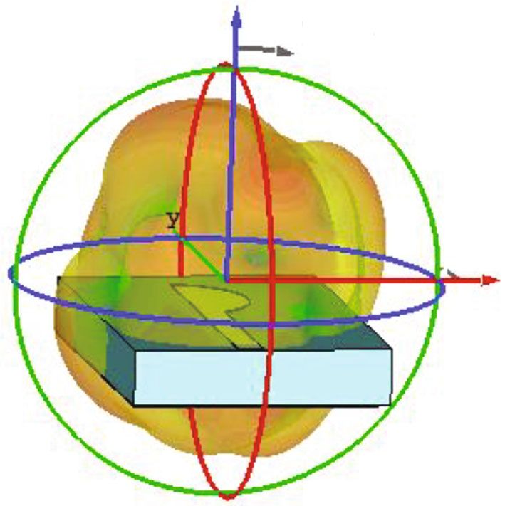
Wireless Communications and Mobile Computing 5

 Voltage standing wave ratio (VSWR)
 3.5

 3

 2.5

 2

 1.5

 1
 20 30 40 50 60 70 80 90 100

 Frequency (GHz)

 Freespace
 (a) (b)
 Z 0
 30 330
 Theta

 60 300

 90 270
 –50 –20 0

 Phi
 X
 120 240

 150 210
 180

 E plane- freespace

 (c) (d)
 0
 30 330

 60 300

 90 270
 –50 –20 0

 120 240

 150 210
 180

 H plane- freespace
 (e)

Figure 3: (a) VSWR, (b) surface current at 60 GHz, (c) 3D radiation pattern, (d) E plane radiation pattern at 60 GHz, and (e) H plane
radiation pattern at 60 GHz.
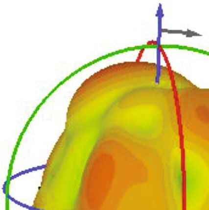
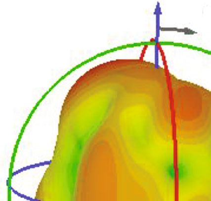
6 Wireless Communications and Mobile Computing

 Z Z
 Theta Theta

 Phi Phi
 X X

 (a) (b)
 0 0
 30 330 30 330

 60 300 60 300

 90 270 90 270
 –50 –20 0 –50 –20 0

 120 240 120 240

 150 210 150 210
 180 180

 E-plane 55 Ghz E-plane 65 Ghz
 (c) (d)
 0 0
 30 330 30 330

 60 300 60 300

 90 270 90 270
 –50 –20 0 –50 –20 0

 120 240 120 240

 150 210 150 210
 180 180

 H-plane 55 Ghz H-plane 65 Ghz
 (e) (f)

Figure 4: (a) 3D radiation at 55 GHz, (b) 3D radiation at 65 GHz, (c) E plane radiation at 55 GHz, (d) E plane radiation at 65 GHz, (e) H
plane radiation at 55 GHz, and (f) H plane radiation at 65 GHz.

2. Antenna Design of the polyester substrate has been considered 0.0045. The
 radiating patch is a semicircular disc with a radius of
Figures 1(a)–1(g) show the details of the antenna design. 1.855 mm placed on top of the substrate. The apex of the
Three layers make up the quasi-self-complementary disc is 2 mm away from a point on the substrate, and this
antenna. The antenna is designed on a 10 mm × 7:00 mm, distance is denoted by “or” in Figure 1. The ground plane
1.5 mm thick 100% polyester substrate. The relative permit- is etched with a leaf-shaped slot that complements the radi-
tivity (εr ) of polyester is 1.9. In this research, the loss tangent ating patch and is linked to the substrate’s bottom layer.
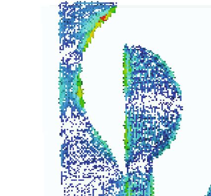
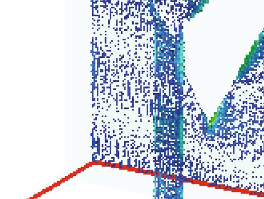
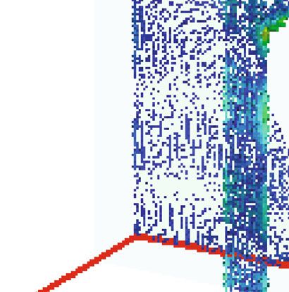
Wireless Communications and Mobile Computing 7

 (a) (b)

 Figure 5: (a) Current distribution at 55 GHz and (b) current distribution at 65 GHz.

Perfect Electric Conductor (PEC) material has been used as magnitude at this frequency is -11.25 dB. The maximum
a patch and ground. The thickness of the ground plane gain is 5.7 dBi with a radiation efficiency of 89.06%. The
and path is 0.035 mm. majority of the surface current is concentrated along the
 The leaf shape is etched from three distinct coexisting semicircular disc’s straight edges and the ground’s equiva-
slots—a circular, a rectangular, and a triangular slot. The cir- lent inner side edges (Figure 3(b)). At 60 GHz, the 3D radi-
cular slot has a radius of 3 mm (denoted by “gcr” in ation pattern is seen in Figure 3(c). The 3D radiation looks
Figure 1). A small rectangular slot, measuring 1:5 mm × like the antenna radiates towards the Z direction with some
0:67 mm, is etched from the right-top corner of the ground. distortion at different angles.
The width of this slot is denoted by “gw1” in Figure 1. This Figures 4(a) and 4(b) depict the antenna’s 3D radiation
rectangular slot creates a partial side (“gl”) on the ground pattern at 55 and 65 GHz, respectively. At 55 GHz and
and is on the same side as the semicircular disc is facing. 65 GHz, the E and H plane radiation patterns are shown in
Lastly, an isosceles triangular slot completes the overall Figures 4(c)–4(f). In this study, it is observed that at lower
shape of the ground slot. The triangle’s legs are denoted by and higher frequencies of 55 GHz and 65 GHz, the radiation
“el” in Figure 1 and measure 4.46 mm. A microstrip feedline patterns are nearly comparable. At 65 GHz, the radiation
with a length of 5.07 mm and a width of 0.70 mm feeds the patterns in both planes are slightly distorted at certain
antenna. The dimension of each of these parameters are angles. Figures 5(a) and 5(b) show the current distribution
given in Table 1. The radiating patch, feedline, and ground of the antenna at 55 GHz and 65 GHz.
are made from 0.035 mm thick Perfect Electric Conductor The return loss curve was barely affected by a change in
(PEC). the dimension of the feed width (fw), while other parameters
 of the antenna were kept constant (Figure 6(a)). The ground
3. Free Space Simulation Results plane’s circular slot size is denoted by the radius “gcr.” The
 optimum radius size is 3 mm. Decreasing the radius to
In free space, the antenna’s return loss curve shows a super- 2.9 mm and 2.8 mm had an insignificant effect on the imped-
wide impedance bandwidth of more than 78 GHz. From ance bandwidth (Figure 6(b)). The relative position of the
Figure 2, it is noted that the antenna works very well at radiating semicircular disc with respect to a fixed point on
-10 dB impedance from 28 GHz to 100 GHz. The impedance the substrate is denoted by the word “or.” The optimum value
bandwidth of this antenna is very large. Three different res- of “or” is 2 mm. When the radiating disc is closer to the point;
onant frequencies were observed—one in the V band and i.e., the position of the disc is moved slightly to the left, the
two others in the W band region (Figure 2). The voltage return loss curve is above -10 dB at around 60 GHz. As the dis-
standing wave ratio (VSWR) at these frequencies is very tance increased, i.e., as the disc was moved slightly to the right,
close to the desired value of 1 (Figure 3(a)). At 60 GHz, a the impedance bandwidth decreased by almost 13 GHz, cover-
good radiation pattern was observed in the E plane ing only the V and W bands (Figure 6(c)). Reduction of
(Figure 3(d)), while the H plane (Figure 3(e)) had very lim- impedance bandwidth can also occur if we increase or
ited radiation with a narrow beam width. The return loss decrease the size of the partial ground side “gl” (Figure 6(d)).
8 Wireless Communications and Mobile Computing

 S-parameters magnitude in dB
 0

 –10

 Reflection coefficient (dB)
 –20

 –30

 –40

 –50

 –60
 20 30 40 50 60 70 80 90 100

 Frequency (GHz)

 fw = 0.7 (original)
 fw = 0.5
 fw = 0.9
 (a)
 S-parameters magnitude in dB
 0

 –10
 Reflection coefficient (dB)

 –20

 –30

 –40

 –50

 –60
 20 30 40 50 60 70 80 90 100

 Frequency (GHz)

 gcr = 3 (original)
 gcr = 2.8
 gcr = 2.9
 (b)

 Figure 6: Continued.
Wireless Communications and Mobile Computing 9

 S-parameters magnitude in dB
 –5

 –10

 –15

 Reflection coefficient (dB)
 –20

 –25

 –30

 –35

 –40

 –45
 20 30 40 50 60 70 80 90 100

 Frequency (GHz)

 or = 2 (original)
 or = 1.8
 or = 2.2
 (c)
 S-parameters magnitude in dB
 0

 –5

 –10
 Reflection coefficient (dB)

 –15

 –20

 –25

 –30

 –35

 –40

 –45
 20 30 40 50 60 70 80 90 100

 Frequency (GHz)

 gl = 10 (original)
 gl = 9
 gl = 9.5
 (d)

Figure 6: Changes in parameters have an impact on return loss: (a) feed width (“fw”), (b) ground circular slot radius (“gcr”), (c) disc
position (“or”), and (d) partial ground length (“gl”).

 Table 2: Antenna parametric change results.

 Final fw = 0:5 fw = 0:9 or = 1:8 or = 2:2 gcr = 2:8 gcr = 2:9 gl = 9 gl = 9:5
Parameters at 60 GHz
 design (mm) (mm) (mm) (mm) (mm) (mm) (mm) (mm)
Return loss magnitude
 -11.25 -12.06 -10.76 -8.91 -16.18 -11.40 -11.13 -22.49 -21.01
(dB)
Gain (dBi) 5.704 5.529 5.858 5.989 4.999 5.634 5.674 6.322 6.425
Radiation efficiency (%) 89.06 88.59 89.35 88.71 88.69 89.76 89.65 92.29 87.89
10 Wireless Communications and Mobile Computing

 Skin 2 mm

 Fat

 Muscle

 (a) (b)
 4 mm 6 mm

 (c) (d)
 8 mm 10 mm

 (e) (f)

Figure 7: (a) Outermost layers of the phantom, antennas placed (b) 2 mm, (c) 4 mm, (d) 6 mm, (e) 8 mm, and (f) 10 mm away from the
phantom.

 Table 3: Dimension and physical properties of skin, fat, and muscle at 60 GHz [28].

 Dimension (mm) Relative permittivity Conductivity Average penetration depth (mm)
Phantom layers
 Length Width Thickness
Skin 18 14 2 7.98 36.39 0.48
Fat 18 14 3 3.13 2.82 3.37
Muscle 18 14 10 12.86 52.83 0.41
Wireless Communications and Mobile Computing 11

 S–parameters magnitude in dB
 0

 –10

 Reflection Coefficient (dB)
 –20

 –30

 –40

 –50

 –60

 –70
 20 30 40 50 60 70 80 90 100

 Frequency (GHz)

 Freespace 6mm
 2mm 8mm
 4mm 10mm

 Figure 8: Simulations of on-body return loss at various distances.

 0 0
 30 330 30 330

 60 300 60 300

 90 270 90 270
 –50 –20 0 –50 –20 0

 120 240 120 240

 150 210 150 210
 180 180
 2 mm 2 mm
 4 mm 4 mm
 6 mm 6 mm
 8 mm 8 mm
 10 mm 10 mm
 E plane freespace H plane freespace
 (a) (b)

 Figure 9: On-body radiation pattern at 60 GHz: (a) E plane and (b) H plane.

In general, at 60 GHz, the gain varied from 5 dBi to 6.4 dBi vary at different frequencies, and for mmWave, these values
while the radiation efficiency ranged from 87.89% to 92.29% are reported in [26]. Millimeter waves are easily blocked by
for various parametric changes. The detailed results for para- obstacles, and at 60 GHz, on average, they can penetrate
metric changes are summarized in Table 2. the skin up to a depth of 0.48 mm. For fat, this value is
 3.37 mm, and for muscle, it is 0.41 mm. To mimic the
4. On-Body Simulation Results human body, a phantom was created by stacking the three
 layers above each other (Figure 7(a)). Table 3 summarizes
Skin, fat, and muscle are the three outermost layers of the the physical characteristics of the phantom human. The
human body. The layers can be characterized by their rela- space between the antenna and the human body model is
tive permittivity or electric conductivity. These parameters shown in Figures 7(b)–7(f).
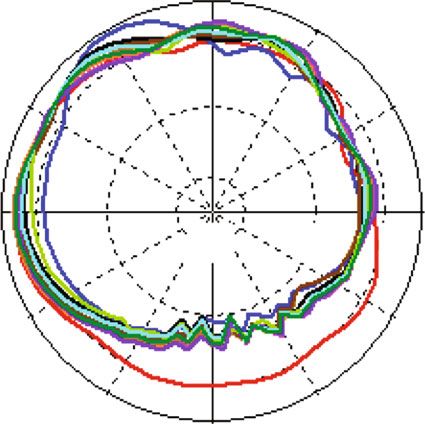
12 Wireless Communications and Mobile Computing

 Voltage standing wave radio (VSWR)
 4

 3.5

 3

 2.5

 2

 1.5

 1
 20 30 40 50 60 70 80 90 100

 Frequency (GHz)
 Free space On-body 6 mm
 On-body 2 mm On-body 8 mm
 On-body 4 mm On-body 10 mm

 Figure 10: Free space and on-body (various distances) VSWR.

 Table 4: On-body results at different gap distances.

Parameters at 60 GHz Free space On-body 2 mm On-body 4 mm On-body 6 mm On-body 8 mm On-body 10 m
Return loss -11.25 -11.69 -11.64 -11.60 -11.29 -11.26
Gain (dBi) 5.704 6.137 5.806 5.813 6.046 5.922
Radiation efficiency (%) 89.06 67.48 75.79 79.02 81.95 83.71

 Table 5: Free space comparison between different substrates.

Substrate Relative permittivity Thickness (mm) Return loss magnitude (dB) Gain (dBi) Radiation efficiency (%)
100% polyester 1.9 1.5 -11.25 5.70 89.06
Jeans 1.7 1 -11.16 5.34 90.38
Denim 1.88 1.5 -11.20 5.83 89.04
Silk 1.75 1.16 -10.61 5.68 89.36
Tween 1.69 1.37 -11.38 6.32 88.71
Panama 2.12 1.04 -09.92 6.27 88.88
Felt 1.38 1.38 -13.15 6.76 91.69
Moleskin 1.45 1.17 -13.08 5.88 91.33
Cotton 1.63 1.5 -11.97 6.99 88.96
Quartzel fabric 1.95 1.5 -11.36 5.66 89.42
Cordura/lycra 1.5 0.5 -14.10 5.91 93.95

 On-body simulations were carried out by placing the At close range, a grating radiation pattern can be seen in
antenna at five different positions away from the phantom, both the E and H planes. The radiation pattern becomes
starting at 2 mm (Figure 7(b)) and ending at 10 mm. When comparable to free space patterns as the gap distance
compared to open space, the antenna’s impedance band- increases. The E plane has some backward radiation towards
width reduced by almost 10 GHz when it was closest to the the phantom at these distances (Figure 9(a)). The H plane
phantom. At this distance, the antenna is covering the V does not exhibit any backward radiation for distances up
and W bands. As the gap between the antenna and the phan- to 4 mm (Figure 9(b)). The maximum gain at 60 GHz
tom increased, the return loss curves were almost identical. increased to a value of more than 6 dBi at a gap distance of
The resonant frequencies hardly shifted at these distances 2 mm and 8 mm. Radiation efficiency at 2 mm decreased to
(Figure 8). 67.48% and gradually increased to 83.71% at the furthest
Wireless Communications and Mobile Computing 13

 S–Parameters magnitude in dB
 0

 –10

 Reflection Coefficient (dB)
 –20

 –30

 –40

 –50

 –60
 20 40 60 80 100

 Frequency (GHz)

 On–body
 100% polyster Moleskin
 Jeans Felt
 Denim Cotton
 Silk Quartzel
 Tween Cordura/Lycra
 Panama

 Figure 11: Simulated on-body return loss at different distances.

 0 0
 30 330 30 330

 60 300 60 300

 90 270 90 270
 –50 –20 0 –50 –20 0

 120 240 120 240

 150 210 150 210
 180 180
 E-plane H-plane
 100% polyester 100% polyester
 Cordura Cordura
 Cotton Cotton
 Denim Denim
 Felt Felt
 Jeans Jeans
 Moleskin Moleskin
 Panama Panama
 Quartzel Quartzel
 Silk Silk
 Tween Tween
 (a) (b)

 Figure 12: Comparison of several textile substrates’ 60 GHz radiation patterns in free space: (a) E plane and (b) H plane.

distance, which is similar to free space efficiency. Figure 10 between this antenna and the human phantom does affect
shows the free space and on-body VSWR for various dis- the VSWR significantly. The on-body and free space simu-
tances away from the body. Results show that the distance lated VSWR results are very close to each other over the
between this antenna and the human phantom does affect large frequency range as shown in Figure 10. On-body sim-
significantly the VSWR. Results show that the distance ulation results are summarized in Table 4. Even though the
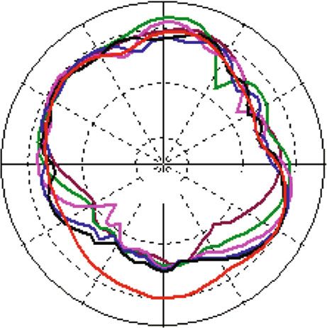
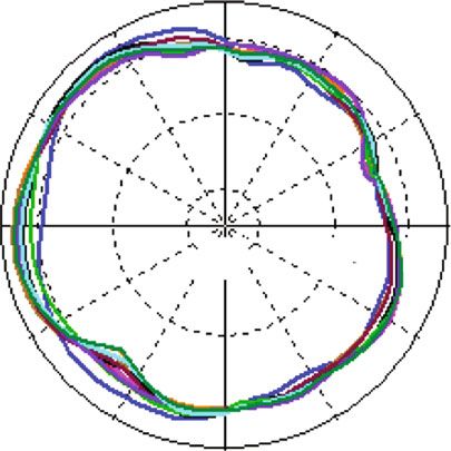
14 Wireless Communications and Mobile Computing

 S–parameters magnitude in dB
 0

 –10

 Reflection Coefficient (dB)
 –20

 –30

 –40

 –50

 –60
 20 40 60 80 100

 Frequency (GHz)

 On-body
 100% polyester Moleskin
 Jeans Felt
 Denim Cotton
 Silk Quartzel
 Tween Cordura/Lycra
 Panama

 Figure 13: Different textile substrate on-body return losses.

 0 0
 30 330 30 330

 60 300 60 300

 90 270
 90 270 –50 –20 0
 –50 –20 0
 120 240
 120 240
 150 210
 150 210 180
 180
 H-plane
 E-plane 100% polyester
 100% polyester Cordura
 Cordura Cotton
 Cotton Denim
 Denim Felt
 Felt Jeans
 Jeans Moleskin
 Moleskin Panama
 Panama Quartzel
 Quartzel Silk
 Silk Tween
 Tween
 (a) (b)

 Figure 14: Comparison of on-body 60 GHz radiation patterns of different textile substrates: (a) E plane and (b) H plane.
Wireless Communications and Mobile Computing 15

 Table 6: On-body comparison between different substrates.

Substrate Relative permittivity Thickness (mm) Return loss magnitude (dB) Gain (dBi) Radiation efficiency (%)
100% polyester 1.9 1.5 -11.64 5.81 75.79
Jeans 1.7 1 -12.03 6.80 73.20
Denim 1.88 1.5 -11.57 5.79 75.73
Silk 1.75 1.16 -11.36 6.07 73.08
Tween 1.69 1.37 -11.96 5.99 74.06
Panama 2.12 1.04 -10.30 6.43 73.94
Felt 1.38 1.38 -14.41 6.25 75.44
Moleskin 1.45 1.17 -14.11 5.98 74.38
Cotton 1.63 1.5 -12.46 6.59 75.04
Quartzel fabric 1.95 1.5 -11.71 5.72 76.08
Cordura/lycra 1.5 0.5 -14.38 8.97 74.40

 Table 7: Comparison with other articles.

 Size length (L) and Operating Relative Bandwidth (GHz) Gain Efficiency Antenna
Antenna Substrate material
 width (W) mm frequency permittivity at -10 dB (dBi) (%) type

 50 × 50 6.95- ECCOSTOCK ∗ DRA
Ref [15] 10 6.95-8.68 5.00
 8.68 GHz HiK antenna
 DRA
Ref [16] ∗ 3.89 GHz 10 ECCOSTOCKHIK 3.50-4.95 5.2 ∗
 MIMO
 350 × 350 3.23– ECCOSTOCK ∗ DRA
Ref [17] 10 3.23–3.59 6.00
 3.59 GHz HiK antenna
This Single
 10 × 7 60 GHz 1.9 Polyester substrate Wideband 5.70 89.06
paper antenna
∗
 Exact value not provided.

human body phantom is made of lossy material, the antenna free space, the polyester substrate was replaced by each of
performance is not much affected by it. the ten substrates. The impedance bandwidth is very close
 to that of free space (see Figure 13). Similar to the previous
5. Various Textile Substrates section’s on-body results, the 60 GHz E plane radiation pat-
 tern for all ten substrates is grated (Figure 14(a)). The H
We analyzed the antenna’s performance further by replacing plane has an insignificant amount of backward radiation
the polyester substrate with ten different textile substrates. (Figure 14(b)). No significant amount of change was seen
These substrates have different relative permittivity and on the maximum gain of these substrates when compared
thickness. Only the thicknesses of these substrates were to free space. The radiation efficiency varied between 73
modified, as they were the same as the polyester. The list and 76%. See Table 6 for more details.
of all ten textiles along with their detailed parameters and The proposed antenna is compared to other articles in
60 GHz free space results is summarized in Table 5. Table 7. The proposed antennas in [1–17] work at lower fre-
 With the exception of the panama textile, the free space quency ranges, and the bandwidth and other performance
impedance bandwidth of nine other textile substrates is well parameters are good. However, the proposed antenna in this
matched to the polyester. The return loss curve of panama study works at a higher frequency band. This antenna shows
was above –10 dB at certain frequencies in the Va and V very large bandwidth, and at -10 dB impedance, it shows
bands (Figure 11). The 60 GHz radiation patterns of all ten 28 GHz to 100 GHz bandwidth. In addition, this proposed
substrates are very comparable to polyester in both the E antenna has a different substrate material compared to the
and H planes (Figure 12). The radiation efficiency of all antennas presented in [15–17]. The physical size of the pro-
the ten substrates was very close to polyester. Tween and posed antenna is also compact due to its high operating
panama’s efficiency was a bit lower than that of polyester’s, frequency.
while cordura/lycra’s efficiency was highest at 93.95%. Cot-
ton and felt’s maximum gain at 60 GHz was almost 7 dBi, 6. Conclusion
while the gain of the rest of the textiles was very similar to
polyester’s value. In this paper, a superwideband QSC textile antenna design is
 The antenna was kept 2 mm away from the phantom for presented. Due to a lack of proper facilities, no measure-
on-body placement. Each of the ten substrates was used to ments were taken and we have only offered simulation
replace the polyester substrate, just like empty space. Like results. Design and simulation were done using CST, which
16 Wireless Communications and Mobile Computing

is known for its reliability. The antenna’s impedance band- [5] B. Almohammed, A. Ismail, and A. Sali, “Electro-textile wear-
width covered three different mmWave bands designated able antennas in wireless body area networks: materials,
by IEEE. Due to high research interest in the 60 GHz V band, antenna design, manufacturing techniques, and human body
we have considered basing our study around the 60 GHz fre- consideration—a review,” Textile Research Journal, vol. 91,
quency. Even though the antenna was not resonant at this no. 5-6, pp. 646–663, 2021.
frequency, the antenna achieved high radiation efficiency [6] X. Y. Wu, L. Akhoondzadeh-Asl, Z. P. Wang, and P. S. Hall,
and a satisfactory amount of gain. The impedance band- “Novel Yagi-Uda antennas for on-body communication at
 60GHz,” in 2010 Loughborough Antennas & Propagation Con-
width is affected by the position of the radiating disc and
 ference, pp. 153–156, Loughborough, UK, 2010.
the size of the ground edges, according to the parametric
 [7] S. Razafimahatratra, J. Sarrazin, A. Benlarbi-Delaï et al., “On-
analysis. For on-body communications, the radiation pat-
 body propagation characterization with an H-plane substrate
terns were distorted, especially close to the phantom. integrated waveguide (SIW) horn antenna at 60 GHz,” in
 The main design of the antenna was based on a noncon- 2015 European Microwave Conference (EuMC), pp. 211–214,
ducting polyester textile substrate. For further evaluation, we Paris, France, 2015.
replaced the substrate with ten different textiles. Both free [8] J. Puskely, M. Pokorny, J. Lacik, and Z. Raida, “Wearable disc-
space and on-body communication simulations were con- like antenna for body-centric communications at 61 GHz,”
ducted. The results are very comparable to the polyester sub- IEEE Antennas and Wireless Propagation Letters, vol. 14,
strate. Good radiation efficiency and gain are maintained pp. 1490–1493, 2015.
throughout the simulations. Compared to reported studies, [9] M. Ur-Rehman, N. A. Malik, X. Yang, Q. H. Abbasi, Z. Zhang,
this proposed design is unique in terms of operating band- and N. Zhao, “A low profile antenna for millimeter-wave
width, radiation efficiency, and choice of materials. In the body-centric applications,” IEEE Transactions on Antennas
future, the upper frequency of the antenna can be further and Propagation, vol. 65, no. 12, pp. 6329–6337, 2017.
extended to investigate the performance of the antenna. [10] N. Chahat, M. Zhadobov, L. Le Coq, S. I. Alekseev, and
Currently, the limitation is that we do not have the high R. Sauleau, “Characterization of the interactions between a
computational resources to simulate the antenna for a wide 60-GHz antenna and the human body in an off-body sce-
range of frequencies, which requires more memory. nario,” IEEE Transactions on Antennas and Propagation,
 vol. 60, no. 12, pp. 5958–5965, 2012.
 [11] K. Islam, T. Hossain, and M. Khan, “A compact novel design
Data Availability of a 60 GHz antenna for body-centric communication,” Inter-
The data used to support the findings of this study are freely national Journal on Communications Antenna and Propaga-
 tion (IRECAP), vol. 10, no. 5, pp. 325–333, 2020.
available at http://niremf.ifac.cnr.it/tissprop/.
 [12] K. Islam, T. Hossain, M. M. Khan, M. Masud, and
 R. Alroobaea, “Comparative design and study of a 60 GHz
Conflicts of Interest antenna for body-centric wireless communications,” Com-
 puter Systems Science and Engineering, vol. 37, no. 1, pp. 19–
The authors declare that they have no conflicts of interest to
 32, 2021.
report regarding the present study.
 [13] N. Chahat, M. Zhadobov, L. Le Coq, and R. Sauleau, “Wear-
 able Endfire textile antenna for on-body communications at
Acknowledgments 60 GHz,” IEEE Antennas and Wireless Propagation Letters,
 vol. 11, pp. 799–802, 2012.
The authors extend their appreciation to the Deanship of
 [14] N. Chahat, M. Zhadobov, S. A. Muhammad, L. Le Coq, and
Scientific Research at King Khalid University for supporting R. Sauleau, “60-GHz textile antenna Array for body-centric
this research through a Research Groups Program under communications,” IEEE Transactions on Antennas and Propa-
Grant (RGP.1/49/42). The authors would like also to thank gation, vol. 61, no. 4, pp. 1816–1824, 2013.
the support from the Taif University Researchers Supporting [15] U. Illahi, J. Iqbal, M. I. Sulaiman et al., “Design of new circu-
Project (TURSP-2020/26), Taif University, Taif, Saudi larly polarized wearable dielectric resonator antenna for off-
Arabia. body communication in WBAN applications,” IEEE Access,
 vol. 7, pp. 150573–150582, 2019.
References [16] J. Iqbal, U. Illahi, M. I. Sulaiman, M. M. Alam, M. M. Su’ud,
 and M. N. Yasin, “Mutual coupling reduction using hybrid
 [1] J. F. Harvey, M. B. Steer, and T. S. Rappaport, “Exploiting high technique in wideband circularly polarized MIMO antenna
 millimeter wave bands for military communications, applica- for WiMAX Applications,” Access, vol. 7, pp. 40951–40958,
 tions, and design,” IEEE Access, vol. 7, pp. 52350–52359, 2019. 2019.
 [2] G. Chittimoju and U. D. Yalavarthi, “A comprehensive review [17] J. Iqbal, U. Illahi, M. N. M. Yasin, M. A. Albreem, and M. F.
 on millimeter waves applications and antennas,” Journal of Akbar, “Bandwidth enhancement by using parasitic patch on
 Physics: Conference Series, vol. 1804, no. 1, article 012205, dielectric resonator antenna for sub-6 GHz 5G NR bands
 2021. application,” Alexandria Engineering Journal, vol. 61, no. 6,
 [3] M. G. Sanchez, “Millimeter-wave communications,” Electron- pp. 5021–5032, 2022.
 ics, vol. 9, no. 2, p. 251, 2020. [18] A. N. Khan, A. A. Ihalage, Y. Ma, B. Liu, Y. Liu, and Y. Hao,
 [4] B. Xu, R. Eike, A. Cliett, R. Cloud, and Y. Li, “A short review of “Deep learning framework for subject-independent emotion
 textile applications in antenna design,” Trends in Textile Engi- detection using wireless signals,” PLoS One, vol. 16, no. 2, arti-
 neering & Fashion Technology, vol. 1, no. 5, 2018. cle e0242946, 2021.
Wireless Communications and Mobile Computing 17

[19] A. Verner and D. Butvinik, “A machine learning approach to
 detecting sensor data modification intrusions in WBANs,” in
 2017 16th IEEE International Conference on Machine Learning
 and Applications (ICMLA), pp. 161–169, Cancun, Mexico,
 2017.
[20] S. B. Roshni, M. P. Jayakrishnan, P. Mohanan, and K. P. Suren-
 dran, “Design and fabrication of an E-shaped wearable textile
 antenna on PVB-coated hydrophobic polyester fabric,” Smart
 Materials and Structures, vol. 26, no. 10, article 105011, 2017.
[21] Y. Mukai and M. Suh, “Development of a conformal woven
 fabric antenna for wearable breast hyperthermia,” Fashion
 and Textiles, vol. 8, no. 1, p. 7, 2021.
[22] J. G. Joshi and S. S. Pattnaik, “Polyester based wearable micro-
 strip patch antenna,” in 2013 IEEE Applied Electromagnetics
 Conference (AEMC), pp. 1-2, Bhubaneswar, India, 2013.
[23] K. Fujiwara, H. Shimasaki, and K. Morimoto, “Studies on a
 fabric feed line sewn to a flexible slot antenna,” in 2016 Inter-
 national Workshop on Antenna Technology (iWAT), pp. 11–
 14, Cocoa Beach, FL, USA, 2016.
[24] P. J. Soh, G. A. E. Vandenbosch, X. Chen, P. S. Kildal, S. L. Ooi,
 and H. Aliakbarian, “Wearable textile antennas' efficiency
 characterization using a reverberation chamber,” in 2011 IEEE
 International Symposium on Antennas and Propagation
 (APSURSI), pp. 810–813, Spokane, WA, USA, 2011.
[25] M. Wissem, EL, L. O. ImenSfar, and J.-M. Ribero, “A textile
 EBG-based antenna for future 5G-IoT millimeter-wave appli-
 cations,” Electronics, vol. 10, no. 2, p. 154, 2021.
[26] M. S. Alam, M. T. Islam, N. Misran, and J. S. Mandeep, “A
 wideband microstrip patch antenna for 60 GHz wireless appli-
 cations,” Elektronica and Elektrotechniek, vol. 19, no. 9,
 pp. 65–70, 2013.
[27] M. M. Khan, K. Islam, M. N. A. Shovon, M. Baz, and
 M. Masud, “Design of a novel 60 GHz millimeter wave Q-
 slot antenna for body-centric communications,” International
 Journal of Antennas and Propagation, vol. 2021, Article ID
 9795959, 12 pages, 2021.
[28] D. Andreuccetti, R. Fossi, and C. Petrucci, Calculation of the
 Dielectric Properties of Body Tissues, Italian National Research
 Council, IFAC-CNR, Florence, Italy, 2005.
You can also read