Degradation Mechanism of Monocrystalline Ni-Rich Li Ni xMnyCoz O2 (NMC) Active Material in Lithium Ion Batteries - IOPscience
←
→
Page content transcription
If your browser does not render page correctly, please read the page content below

Journal of The Electrochemical
Society

OPEN ACCESS

Degradation Mechanism of Monocrystalline Ni-Rich Li[Nix Mny Coz ]O2
(NMC) Active Material in Lithium Ion Batteries
To cite this article: P. Teichert et al 2021 J. Electrochem. Soc. 168 090532

View the article online for updates and enhancements.

                                This content was downloaded from IP address 46.4.80.155 on 12/11/2021 at 08:58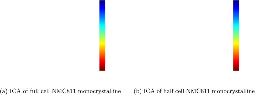
Journal of The Electrochemical Society, 2021 168 090532

                               Degradation Mechanism of Monocrystalline Ni-Rich
                               Li[NixMnyCoz]O2 (NMC) Active Material in Lithium Ion Batteries
                               P. Teichert,1 H. Jahnke,1 and E. Figgemeier2,3,z
                               1
                                 Volkswagen AG, 38239 Salzgitter, Germany
                               2
                                 Aging Processes and Lifetime Prediction of Batteries, Institute for Power Electronics and Electrical Drives (ISEA), RWTH
                               Aachen University, Jaegerstrasse 17-19, 52066 Aachen, Germany
                               3
                                 Helmholtz Institute Münster (HI MS), Forschungszentrum Jülich, 52066, Aachen, Germany

                 Lithium ion batteries are the enabler for electric vehicles and, hereby, a sustainable and green mobility in the future. However, there
                 are high requirements regarding electric vehicles which can be translated into great demands of life time and sustainibility on cell
                 level. Ni-rich Li[NixMnyCoz]O2 (NMC), where x ⩾ 0.6, became the state of the art electrode material for the positive electrode to
                 meet energy and power demands. However, further optimization is required to increase the life time and safety of those materials.
                 An approach is the change from polycrystalline NMC to single crystals to increase the intrinsic stability by suppressing degradation
                 phenomena like particle cracking. In this work, we show that particle cracking is still an issue for monocrystalline Ni-rich NMC811
                 under moderate abusive conditions. Intragranular cracking, i.e. cracking within the primary particle, was revealed as a result of
                 structural degradation of the NMC structure accompanied with oxygen release and cross-talks which affected the SEI and,
                 ultimately, accelerated the ageing of the single crystal NMC811 containing cell compared to its polycrystalline counterpart.
                 © 2021 The Author(s). Published on behalf of The Electrochemical Society by IOP Publishing Limited. This is an open access
                 article distributed under the terms of the Creative Commons Attribution 4.0 License (CC BY, http://creativecommons.org/licenses/
                 by/4.0/), which permits unrestricted reuse of the work in any medium, provided the original work is properly cited. [DOI: 10.1149/
                 1945-7111/ac239f]

                 Manuscript submitted July 2, 2021; revised manuscript received August 26, 2021. Published September 16, 2021.

    Lithium ion batteries gathered importance as energy storage                        electrolyte additives,19 applying a surface coating onto the
device for portable devices, e.g. smartphones and notebooks, grid-                     active material of the active material to diminish side reactions at
level energy storage and automotive applications. For the latter, i.e.                 the electrode-electrolyte-interface20 or doping the electrode active
battery electric vehicles (BEV), hybrid electric vehicles (HEV) and                    material to stabilize the structure at highly delithiated states.21 The
plug-in hybrid electric vehicles (PHEV), there are ever increasing                     modification of the morphology of the NMC particles from a
demands for higher specific energy densities of the LiB to extend the                   polycrystalline structure to a monocrystalline one is a simple and
range of the vehicles for a broader customer’s acceptance for a                        proven strategy to diminish material degradation and thereby ageing
greener transportation.1 As approx. 80 % of transportation belong to                   of the LiB. The synthesis and beneficial properties were reported for
on-road vehicles in the U.S. and Germany, EVs will help to decrease                    NMC532,22,23 NMC62224 and NMC811.25 The main claim of
the carbon footprint of this sector. Beside the demands on the                         monocrystalline active materials is that particle cracking is avoided
mileage of the EVs and thereby the specific energy density of the                       due to the absence of grain boundaries.26,27 Particle cracking is a
LiB also the costs, safety and the lifetime of the LiB are important                   known mechanism which increases the electroactive surface of the
regarding the market acceptance. It is noteworthy that an increased                    active material during ageing and, thereby, facilitates side reactions
specific energy density of the LiB can be a lever to reduce costs at                    like electrolyte degradation and gas formation.17,28–30
system level.2,3 Recently, Tesla presented several approaches to                           However, it was shown recently25,31,32 that a small amount of
decrease the cost per kWh of the cell and increase the specific energy                  cracking may be seen under abusive condition, i.e. very high upper
density by using different cell designs. Further, they announced a                     cutoff voltages, for monocrystalline NMC with various Ni contents.
1000 km battery. This meets the high demands for next-generation                       In this work, we show that minor cracking can be a result of the
batteries ( > 400 Wh · kg−1, > 500 Wh · L−1).4,5 In the past years                     formation of twin boundaries during synthesis and severe intragra-
the specific energy density of the LiB was elevated by changes in the                   nular cracking can be found in Ni-rich single crystal NMC
cell chemistry and its intrinsic stability at higher voltages. Both help               (Ni ⩾ 80%) at moderate upper cutoff voltages during cyclic ageing
to increase the energy.6 Ni-rich Li[NixMnyCoz]O2, x + y + z = 1                        in NMC811/C full cells with reference electrode.
(NMC), where x ⩾ 0.67 have become the most important factor to
further push the capacity of the cells, since the active material of the                                               Experimental
positive electrode present the bottleneck as their specific capacity
(q < 200 mAh g−1) is much smaller compared to graphite as active                           All tests were carried out in PAT cells from EL Cell with the so
material for the negative electrode (q = 360 mAh g−1). Such mate-                      called PAT Core system. Here, a Whatman GF glas fiber separator
rials like Li[Ni0.6Mn0.2Co0.2]O2 (NMC622) and Li[Ni0.8Mn0.1                            (thickness = 260 μm) is used and a Li metal ring reference electrode
Co0.1]O2 (NMC811) were widely investigated recently.8 Generally,                       made of metallurgic Li metal is built in the core on the same height
the specific capacity of NMC active materials rise as the Ni ratio                      level as the separator. The separators were build and sealed in a
is increased, since more Li can be extracted at the same upper                         glove box under Ar atmosphere (H2O < 0.1 ppm, O2 < 0.1 ppm) and
cutoff voltage. Simultaneously, the higher amounts of extracted Li                     delivered in this atmosphere. The cell bodies were dried in a
diminish the intrinsic stability of the material and thereby its safety                convection drying cabinet at 60 °C for at least 3h and inserted into
properties, since for example a high amount of highly reactive Ni4+                    the glove box under vacuum overnight. The electrolyte was a
is formed due to charge compensation.9,10 The latter is leading to                     mixture of DMC:EC:DEC (1:1:1 w/w, Solvonic, Battery grade)
numerous degradation phenomena such as particle cracking, gassing,                     with 1 M LiPF6 as Li containing conductive salt. For the tests,
phase transformations and cation mixing leading to capacity fading,                    200 μ L were introduced in every cell. The positive electrode sheets
impedance rise and ultimately to failure of the LiB.11–18                              were supplied by Novonix Ltd. with the materials specified in
    A wide range of mitigating strategies were published focusing                      Table I.
e.g. on stabilizing the electrode-electrolyte-interface by utilizing                       Coins (diameter = 18 mm) were punched out of the electrode
                                                                                       sheets with an EL Cut from EL Cell. After cutting, the coins were
                                                                                       dried in a Büchi glass oven D-585 Drying at 150 °C under vacuum
  z
      E-mail: egbert.figgemeier@isea.rwth-aachen.de                                     over night. Negative electrode coins were produced, pre-cut, dried
Journal of The Electrochemical Society, 2021 168 090532
Table I. Positive electrode materials.
Material Morphology Supplier Loading D50 particle size
−2
NMC622 polycrystalline Shanshan 3.40 mAh · cm 12.96 μm
NMC622 monocrystalline EA Spring 3.47 mAh · cm−2 4.20 μm
NMC811 polycrystalline BTR 3.00 mAh · cm−2 11.36 μm
NMC811 monocrystalline BTR 2.96 mAh · cm−2 3.60 μm
and packed under Ar atmosphere by Custom Cells Itzhoe (see low C-rates (C/10) which only leads to small overpotentials. Under
Table II). The cell assembling was carried out in a glove box these conditions the kinetic disadvantages of the single crystal
(MBraun, H2O < 0.1 ppm, O2 < 0.1 ppm). Afterwards, the cells material is not noticeable. However, a moedestly higher delithiation
were transfered into CTS climate chambers to provide constant of the monocrystalline NMC electrode is indicated by the results.
temperature during testing and connected to a BioLogic VMP3 with However, according to previous findings for Ni-poorer NMC
EIS enabled cell testing. chemistries the monocrystalline morphology is believed to show a
The cells underwent a formation procedure and an initial higher stability.22–25 This assumption is declined by the results of
characterization. This included a capacity probe with three cycles capacity retention shown in Fig. 2. Here, a faster capacity fade is
CCCV/CC with a C-rate of C/10 and a cutoff current of C/20 at the noticeable for NMC811SC cells compared to their polycrystalline
end of the CV phase. The measured capacity of the last cycle defined counterpart. In the end, less cycles can be performed with the SC
the following C-rates. Afterwards, a galvanostatic electrochemical material (100 cycles (SC) vs ⩾150 cycles (PC)).
impedance spectroscopy (GEIS) and the determination of DC Since the capacity determination is carried out at a low C-rate
internal resistance (DCIR) was carried out according to Table III. (C/10) where low overpotentials can be expected, the voltage curve
The value of the DCIR is the quotient of the difference of the open can be further investigated by differential voltage analysis.33–36 In
circuit voltage right before the current step (VOC) and the last voltage the DVA, the two intercalation steps II (LiC12) and III (LiC18) are
during the current step (Vend) devided by the current (I) (see Eq. 1). both noticeable as local minima (compare to Fig. 3). Considering the
capacity difference between both, there is an indication of loss of
Vend − VOC active material on the negative electrode site as long as there is
RDCIR = [1]
I. enough mobile Li in the system.35 The loss of graphite active
material as used here can have several origins. For example an
A cyclic ageing test were performed with 25 cycles CCCV/CC amorphization of the graphite structure could occur.34 As a result Li
with a C-rate of 1C to a cutoff current of C/10 followed by a would be stored in a capacitor-like manner in the electrochemical
characterization equal to the initial one. The latter was repeated until double layer instead of intercalating into the graphite structure.
a state of health (SoH) of 70% was reached. The voltage range Hence, the intercalation steps would not be clearly noticeable
remained constant throughout the whole cycling test between anymore. Another possibility is that the negative electrode could
3.0 V–4.3 V at full cell level. The C-rate was adjusted after each detach off the electrical network and current collector. The latter
characterization accordingly to the measured capacity. Following the would lead to an abrupt capacity drop. Accordingly, both, i.e.
cyclic aging test, positive electrodes were extracted for post-mortem amorphization and detachment, can be neglected. Another reason
analysis by scanning electron microscopy. Therefore, the cells are can be cross-talk reactions between anode and cathode. Hereby,
disassembled in the glove box and the positive electrodes are washed degradation products of the positive electrode, e.g. dissolved
with DMC to remove solvent and conductive salt residues. transition metal ions or degraded electrolyte, can shuttle toward
the negative graphite electrode. There, pores can become clogged or
Results and Discussion the SEI disturbed which seemingly lead to a loss of active material
The results of the NMC622 positive electrodes containing cells of the negative electrode and loss of lithium storage sites, since
(in the following Sections the cell will be named accordingly to the utilization of the graphite active material is hindered.37–39
morphology of their containing positive electrode after: poly crystals In this work, the loss of Li storage sites by loss of active material
—PC, single crystals—SC) in both morphological configurations (LAMNE) of the negative graphite electrode is taken as an indicator
revealed no new findings and, thus, are not further discussed, since of the impact of the degradation of the postive electrode on the full
the beneficial effect of the monocrystalline morphology for this cell aging. As Fig. 4 shows, the courses of LAMNE and SoH show
chemistry is already well reported.24–27 Still, the results can be found similarities but also differences. Again, NMC622 shows the litera-
in the following Figures. and are used for the discussion of the ture known behavior and becomes more noticeable in the DVA. The
findings of the NMC811. LAMNE is smaller than the overall capacity loss for NMC622,
The supplier recommended an upper cutoff voltage of 4.3 V vs which is vice versa for NMC811. Here, the losses are over 30% but
Li/Li+ for the NMC811 materials. During testing the actual upper still enough mobile Li is available to fill the graphite beyond
NMC potential was slightly above that limit at approx. 4.38 V vs intercalation step II. In case for NMC811, the counter electrode is
Li/Li+ as Fig. 1 shows. Hence, the active materials of the posivite oversized by approx. 33% so that Li plating is not an issue during the
electrode are under moderate abusive conditions during the cycling. cycles where a massive LAMNE takes place (see Fig. 5). Especially
Initially, a capacity of 147.5 mAh g−1 (6.86 mAh total capacity) was during formation and the first cycles the most severe degradation on
found in the NMC811PC cell and 149.2 mAh g−1 (7.58 mAh total the graphite electrode site seems to occur as indicate by DVA
capacity) in the NMC811SC cell. The capacity was determined at results. However, during those cycles only little capacity fade is
noticeable. Hence, it can be assumed that the degradation me-
Table II. Detailed information about graphite negative electrode. chanism of the single crystalline positive electrode leads to
accelerated ageing. Hereby, mainly the graphite active materials is
Active material Graphite affacted in the first cycles (up to 50 cycles). In the same time span,
there is only litte influence of the Li inventory of the LiB.
Specific energy density 350 mAh g−1 Nevertheless, during the DC inner resistance test kinetic hin-
Active material content 96 % drance due to degradation phenomena is revealed since higher
Areal capacity 4.0 mAh cm−2 C-rates are used compared to the capacity determination. The latterJournal of The Electrochemical Society, 2021 168 090532
Table III. Detailed information about electrochemical impedance spectroscopy and determination of DC inner resistance.
Step Command Step information
1 Charge CC C/3 to upper cutoff voltage
2 Charge CV C/20
3 Pause 5 min
4 Discharge CC C/20 to potential of positive electrode equal to SoC 95%
5 GEIS 100 kHz–10 mHz, Ia = 2mA
6 DCIR Rest 5 min
7 DCIR Charge CC 2.5C for 18 s or upper cutoff voltage
8 DCIR Rest 5 min
9 DCIR Discharge CC 2.5C for 18 s or lower cutoff voltage
10 DCIR Rest 5 min
11 Discharge CC C/20 to potential of positive electrode equal to SoC 50%
12 GEIS 100 kHz–10 mHz, Ia = 2 mA
13–17 DCIR Repeat steps 6–10
18 Discharge CC C/20 to potential of positive electrode equal to SoC 5%
19 GEIS 100 kHz–10 mHz, Ia = 2 mA
20–24 DCIR Repeat steps 6–10
Figure 3. Scheme to illustrate position of minima in the differential voltage
analysis (DVA) that indicate intercalation steps II and III.
Figure 1. Potential of NMC811SC electrode vs Li/Li+ (blue) and full cell
voltage (orange) at 23 °C and C/10.
Figure 2. Course of the state of health (SoH) of NMC622PC cell (red), Figure 4. Course of the loss of active material of negative electrode of
NMC622SC cell (black), NMC811PC cell (blue), NMC811SC cell (yellow) NMC622PC cell (red), NMC622SC cell (black), NMC811PC cell (blue),
over total number of cycles with three devices under testing (DUT). NMC811SC cell (yellow) over total number of cycles.Journal of The Electrochemical Society, 2021 168 090532
Figure 7. Results of DC inner resistance tests at the positive electrode site at
SoC 50% for NMC622 (black) and NMC811 (blue) in both, monocrystalline
(dotted line) and polycrystalline (solid line) morphology.
no morphological changes seem to occur during aging of the
NMC622 electrodes. The appearance of the NMC811 electrodes
Figure 5. Cycling data of NMC811SC cell with full cell voltage (black), after cycling is different. Regarding the polycrystalline NMC811
cathode potential (red) and anode potential (blue). Black solid line represents electrodes, there are morphological changes noticeable as they are
Li plating boundary at 0V vs Li/Li+. Curves are recorded during cycling at already described elsewhere.8 The evolution of intergranular cracks,
1C//1C and capacity probe at C/10//C/10 at 23 °C. i.e. at the grain boundaries between the primary particles, becomes
obvious as a results of the aging. These cracks can increase the
surface area and, thereby, the electroactive surface. As a result, the
resistance can be lowered but also the tendency for side reactions is
increased.
A surprising result is shown in Figs. 8g and 8h. The pristine
material of monocrystalline NMC811 shows the expected particle
shape. Additionally, some grain boundaries are noticeable which can
be a result of insufficient milling after synthesis. The latter should
not affect the performance of the material at all. However, the
appearance of the material after cycling to a cell SoH of 70% reveals
remarkable morphological changes which were unexpected. To best
of author’s knowledge, such a degradation was not reported else-
where, yet.
In the SEM image some larger cracks are noticeable. Regarding
the pristine material (Fig. 8g) it is obvious that the NMC811 particle
do not have a purely monocrystalline morphology. There are
particles, where some single crystals are packed together. This
Figure 6. Results of DC inner resistance tests at the negative electrode site results in the formation of grain boundaries. During cycling, a
at SoC 50% for NMC622 (black) and NMC811 (blue) in both, monocrystal- frequent mechanical stress is applied on the grain boundaries due to
line (dotted line) and polycrystalline (solid line) morphology. anisotropic volume changes of the unit cell of the NMC during Li
insertion and extraction. Intergranular cracks are induced as result of
mechanical fatigue of the grain boundaries.16,41 In a worst case
is noticeable in Fig. 6. Here, the NMC811SC cell reveals an scenario, loss of Li inventory could occur due to disconnection of a
accelerated resistance growth at the negative electrode site. The particle to the matrix. Furthermore, there is a large number of micro-
latter indicates worsen kinetics due to cross-talks and shuttle reaction and nanocracks visible, respectively. These were not noticeable at
as a result of the degradation of the NMC electrode. the pristine material and, thus, must be a result of aging. It is
Interestingly a decrease of the DC inner resistance of the positive unlikely that these intragranular cracks, i.e. within the primary
electrode is shown in Fig. 7. This can be a result of the decreased particle, are only a result of mechanical fatigue, since the cracks are
currents, since the C-rate for the pulses was adjusted accordingly to distributed homogeneously and randomly in the particle. Ryu et al.31
the current capacity similar to C-rates during cycling. However, it recently reported the evolution in Ni-rich NMC single crystals after
could also suggest particle cracking which leads to an increased electrochemical cycling. Their findings revealed intragranular cracks
surface area which improves the kinetics. Similar results were found as a result of an inhomogeneous spatial Li distribution within the
using electrochemical impedance spectroscopy.40 single crystal NMC particle. The latter lead to tensile, compressive
For a deeper insight into the degradation mechanism cross- and shear stress in the particle, which is released by layer plane
section images of the NMC electrodes are taken in pristine and aged gliding in the lattice. Thereby, intragranular cracks are formed
state. Therefore, the cells are disassembled after the aging tests in the parallel to the (003) plane.31 This mechanism is also reported for
glove box and the electrodes are extracted. Afterwards, to remove intragranular crack formation in NMC333.32 However, in both
residues of Li containing salt and solvents, the positive electrodes reports the density of intragranular cracks are lower compared to
are rinsed with DMC and dried in the glove box. Cross-sections of the findings in this work. Additionally, intragranular cracks due to
pristine and aged NMC electrodes are made with an Ar ion mill. The mechanical stress are only found parallel to the (003) lattice plane,
cross-sections are transferred into the scanning electron microscope. which is not the case in this work as Fig. 8h reveals. Here, it is
There, images are taken by using secondary electrons. noticeable that cracks are distributed anistropically and nonparallel
Figure 8 gives an overview over the cross-section images of the within the particle. Hence, there must be an addtional degradation
pristine and aged positive NMC electrodes. As Figs. 8a–8d reveal, mechanism.Journal of The Electrochemical Society, 2021 168 090532 Figure 8. Overview of cross-section images of pristine and aged NMC electrode materials. Electrical data (see Figs. 2 and 4) already indicated a large was the same for all tests. A known degradation mechanism for degradation of the cell, where seemingly degradation of the positive Ni-rich NMC electrodes are phase transformations. Hereby, the electrode affected the aging the most since the negative electrode layered transition metal oxide structure (R3̅m) is transformed to a
Journal of The Electrochemical Society, 2021 168 090532

Figure 9. Incremental capacity analysis of NMC811 monocrystalline electrode containing cell. ICA derived from full cell voltage 9a and half cell potential of
the positive electrode 9b.

spinel structure (Fd3̅m) and, ultimately, into a rock-salt structure                                                Conclusions
(Fm3̅m).17,30 The structural degradation leads to volumetric changes
                                                                                     In conclusion, the change to a monocrystalline morphology can
of the phase and can induce mechanical stress and cracks within the
                                                                                 have a beneficial effect as the result of NMC622 electrodes containing
primary particle. The phase transformation starts at the surface of the
                                                                                 cells shows. However, under abusive conditions, i.e. elevated upper
particle and the reaction layer grows anisotropic to the particle
                                                                                 cutoff voltages, the advantageous behavior may not appear anymore
center. Here, the reaction kinetics are faster in direction of lithation,
                                                                                 as the results of NMC811 showed, which can be due to both,
i.e. crystallographic direction a, than perpendicular to it.42 Regarding
                                                                                 the material’s nature and the elevated upper cutoff voltage. The latter
the stoichiometry, the degradation structure has an oxygen deficit
                                                                                 is known to pronounce degradation of the active material and aging
compared to the pristine structure which leads to excess oxygen
                                                                                 of the cell by a number of degradation mechanisms, e.g. phase
which is released from the lattice. It was reported that this released
                                                                                 transformation of the NMC active material, faciliation of cracking and
oxygen can be highly reactive singlet oxygen 1O2. The latter
                                                                                 electrolyte consumption. Whereas the change of morphology to single
degrades the electrolyte and triggers further degradation, e.g.
                                                                                 crystals impedes some ageing phenomena like particle cracking.
formation of water and HF.15,18,43 Degradation products formed at
                                                                                 However, the results may suggest that other degradation phenomena,
the NMC electrode site are able to shuttle toward the negative
                                                                                 e.g. phase transformation of the NMC active material, could be
electrode and can cause there side reactions. There, the degradation
                                                                                 amplified. The findings in this work reveal a massive morphological
products can disturb or damage the SEI, which leads to an additional
                                                                                 breakdown of the Ni-rich NMC811 single crystals as a result of cyclic
SEI growth. Thereby, mobile Li is consumed.38,39 The oxygen
                                                                                 aging, which goes beyond previous findings of Ryu et al.31 and Yan
release and phase transformation is mainly triggered by the
                                                                                 et al.32 This is the first time that such a breakdown is reported. Beside
spontaneous reduction of highly reactive Ni4+ which is presented
                                                                                 the mechanical stress due to inhomogeneous spatially Li distribution,
in highly delithiated states of the Ni-rich NMC. Since the kinetics of
                                                                                 its origin is assumed in the spontaneous reduction of highly reactive
the oxygen release are faster compared to the reaction rates of phase
                                                                                 Ni4+ which can be found at high delithated states of the positive
transformation, oxygen vacancies are induced and can agglomerate.
                                                                                 electrode, i.e. at high SoC. The reduction leads to phase transformation
Finally, intragranular cracks are formed as Mu et al.44 have shown in
                                                                                 from the pristine layered transition metal oxide structure (R3̅m) to
their studies. Figure 8h reveals a massive degradation of the NMC
                                                                                 spinel structure (Fd3̅m) and further to rock-salt structure (Fm3̅m).
electrode which agrees well with the findings of the cycling aging.
                                                                                 Both degraded structures show an oxygen deficit compared to the
    An incremental capacity analysis (dQ/dU)15,36,43 was carried out
                                                                                 pristine structure. Furthermore, the reduction of Ni4+ leads to oxygen
in addition to gain further understanding of the findings. A pseudo-
                                                                                 release from the lattice. Since the oxygen release kinetics are faster
OCV curve was recorded in the 3-electrode set-up during capacity
                                                                                 than the phase transformation rate, oxygen vacancies are formed
probe at low C-rates (C/10) to maintain small overpotential at the
                                                                                 which agglomerate and induce intragrunalar cracking. The latter is
electrodes. The pOCV curve of the full cell voltage (Fig. 9a) and the
                                                                                 mainly found in the degraded NMC811 single crystals since inter-
NMC half cell potential (Fig. 9b) were derived to calculate the ICA
                                                                                 granular cracks as a result of mismatching strains at grain boundaries
(dQ/dU). Especially in the NMC electrode half cell potential derived
                                                                                 are mainly declined by the particle morphology.
ICA a narrowing of the voltage window over the aging is noticeable
(see Fig. 9, compare blue curve (SoH 100%) to red curve (approx.
                                                                                                                    Disclaimer
SoH 70%)). This can be a result of loss of Li inventory and kinetic
hindering at lower positive electrode potentials as reported                        The results, opinions and conclusions expressed in this work are
elsewhere.45 As a result, the lithiation level of the NMC electrode              not necessarily those of Volkswagen Aktiengesellschaft.
at a fully discharge state of the full cell will decrease over the course
of aging. Interestingly, the peak around 4.2 V vs Li/Li+ becomes                                                       ORCID
more pronounced as aging proceeds. This peak is attributed to a
irreversible phase transformation where oxygen release from the                  E. Figgemeier         https://orcid.org/0000-0002-6621-7419
NMC lattice takes place.15,46 This pronounced reaction at this
potential can compensate lost Li inventory so that capacity losses                                                   References
appear less severe. At the same time, the degradation which occurs                1. H.-H. Ryu, K.-J. Park, C. S. Yoon, and Y.-K. Sun, “Capacity fading of ni-rich li [ni
at this potential of 4.2 V vs Li/Li+ is amplified to accelerates the                  x co y mn1-x-y] o2 (0.6 ⩽ x ⩽ 0.95) cathodes for high-energy-density lithium-ion
breakdown of the cell by degenerating the active material of the                     batteries: bulk or surface degradation?” Chemistry of materials, 30, 1155 (2018).
                                                                                  2. G. G. Eshetu, D. Mecerreyes, M. Forsyth, H. Zhang, and M. Armand, “Polymeric
posivite electrode, electrolyte consumption due to oxygen release off                ionic liquids for lithium-based rechargeable batteries.” Molecular Systems Design
the NMC lattice and, thereby, consumption of mobile Li.                              & Engineering, 4, 294 (2019).
Journal of The Electrochemical Society, 2021 168 090532
3. M. Winter, B. Barnett, and K. Xu, “Before li ion batteries.” Chem. Rev., 118, 11433 25. G. Qian, Y. Zhang, L. Li, R. Zhang, J. Xu, Z. Cheng, S. Xie, H. Wang, Q. Rao,
(2018). Y. He, Y. Shen, L. Chen, M. Tang, and Z.-F. Ma, “Single-crystal nickel-rich
4. X. Zeng, M. Li, D. Abd El-Hady, W. Alshitari, A. S. Al-Bogami, J. Lu, and layered-oxide battery cathode materials: Synthesis, electrochemistry, and intra-
K. Amine, “Commercialization of lithium battery technologies for electric granular fracture.” Energy Storage Materials, 27, 140 (2020).
vehicles.” Adv. Energy Mater., 9, 1900161 (2019). 26. J. Li, H. Li, W. Stone, S. Glazier, and J. R. Dahn, “Development of electrolytes for
5. Richard Schmuch, Ralf Wagner, Gerhard Hörpel, Tobias Placke, and single crystal nmc532/artificial graphite cells with long lifetime.” J. Electrochem.
Martin Winter, “Performance and cost of materials for lithium-based rechargeable Soc., 165, A626 (2018).
automotive batteries.” Nat. Energy, 3, 267 (2018). 27. S. Sharifi-Asl, G. Chen, J. Croy, M. Balasubramanian, and R. Shahbazian-Yassar,
6. W. Li, E. M. Erickson, and A. Manthiram, “High-nickel layered oxide cathodes for “Aberration-corrected scanning transmission electron microscopy of single crystals
lithium-based automotive batteries.” Nat. Energy, 5, 26 (2020). and chemically-gradient nmc cathodes.” Microscopy and Microanalysis, 24, 1536
7. X. Judez, G. G. Eshetu, C. Li, L. M. Rodriguez-Martinez, H. Zhang, and (2018).
M. Armand, “Opportunities for rechargeable solid-state batteries based on li- 28. F. H. Pavoni, L. E. Sita, C. S. dos Santos, S. P. da Silva, P. R. C. da Silva, and
intercalation cathodes.” Joule, 2, 2208 (2018). J. Scarminio, “Licoo2 particle size distribution as a function of the state of health of
8. P. Teichert, G. G. Eshetu, H. Jahnke, and E. Figgemeier, “Degradation and aging discarded cell phone batteries.” Powder Technology, 326, 78 (2018).
routes of ni-rich cathode based li-ion batteries.” Batteries, 6, 8 (2020). 29. H. Nara, K. Morita, D. Mukoyama, T. Yokoshima, T. Momma, and T. Osaka,
9. S.-M. Bak, E. Hu, Y. Zhou, X. Yu, S. D. Senanayake, S.-J. Cho, K.-B. Kim, “Impedance analysis of lini 1/3 mn 1/3 co 1/3 o 2 cathodes with different
K. Y. Chung, X.-Q. Yang, and K.-W. Nam, “Structural changes and thermal secondary-particle size distribution in lithium-ion battery.” Electrochimica Acta,
stability of charged linixmnycozo2 cathode materials studied by combined in situ 241, 323 (2017).
time-resolved xrd and mass spectroscopy.” ACS applied materials & interfaces, 6, 30. F. Lin, I. M. Markus, D. Nordlund, T.-C. Weng, M. D. Asta, H. L. Xin, and
22594 (2014). M. M. Doeff, “Surface reconstruction and chemical evolution of stoichiometric
10. Y. Zhang, Y. Katayama, R. Tatara, L. Giordano, Y. Yu, D. Fraggedakis, J. G. Sun, layered cathode materials for lithium-ion batteries.” Nat. Commun., 5, 3529 (2014).
F. Maglia, R. Jung, M. Z. Bazant, and Y. Shao-Horn, “Revealing electrolyte 31. H.-H. Ryu, B. Namkoong, J.-H. Kim, I. Belharouak, C. S. Yoon, and Y.-K. Sun,
oxidation via carbonate dehydrogenation on ni-based oxides in li-ion batteries by “Capacity fading mechanisms in ni-rich single-crystal ncm cathodes.” ACS Energy
in situ fourier transform infrared spectroscopy.” Energy & Environmental Science, Lett., 6, 2726 (2021).
13, 183 (2020). 32. P. Yan, J. Zheng, M. Gu, J. Xiao, J.-G. Zhang, and C.-M. Wang, “Intragranular
11. U.-H. Kim, D.-W. Jun, and K.-J. Park et al., “Pushing the limit of layered transition cracking as a critical barrier for high-voltage usage of layer-structured cathode for
metal oxide cathodes for high-energy density rechargeable li ion batteries.” Energy lithium-ion batteries.” Nat. Commun., 8, 14101 (2017).
& Environmental Science, 11, 1271 (2018). 33. P. Keil and A. Jossen, “Calendar aging of nca lithium-ion batteries investigated by
12. F. Schipper, E. M. Erickson, C. Erk, J.-Y. Shin, F. F. Chesneau, and D. Aurbach, differential voltage analysis and coulomb tracking.” J. Electrochem. Soc., 164,
“Review–recent advances and remaining challenges for lithium ion battery A6066 (2017).
cathodes.” J. Electrochem. Soc., 164, A6220 (2017). 34. H. M. Dahn, A. J. Smith, J. C. Burns, D. A. Stevens, and J. R. Dahn, “User-friendly
13. T. Li, X.-Z. Yuan, L. Zhang, D. Song, K. Shi, and C. Bock, “Degradation differential voltage analysis freeware for the analysis of degradation mechanisms in
mechanisms and mitigation strategies of nickel-rich nmc-based lithium-ion bat- li-ion batteries.” J. Electrochem. Soc., 159, A1405 (2012).
teries.” Electrochemical Energy Reviews, 3, 43 (2020). 35. M. Lewerenz, A. Marongiu, A. Warnecke, and D. U. Sauer, “Differential voltage
14. M. Tang, J. Yang, N. Chen, S. Zhu, X. Wang, T. Wang, C. Zhang, and Y. Xia, analysis as a tool for analyzing inhomogeneous aging: A case study for lifepo4-
“Overall structural modification of a layered ni-rich cathode for enhanced cycling graphite cylindrical cells.” Journal of Power Sources, 368, 57 (2017).
stability and rate capability at high voltage.” Journal of Materials Chemistry A, 7, 36. C. Pastor-Fernández, K. Uddin, G. H. Chouchelamane, W. Dhammika Widanage,
6080 (2019). and J. Marco, “A comparison between electrochemical impedance spectroscopy and
15. R. Jung, M. Metzger, F. Maglia, C. Stinner, and H. A. Gasteiger, “Oxygen release incremental capacity-differential voltage as li-ion diagnostic techniques to identify
and its effect on the cycling stability of Li[NixMnyCoz]O2 (NMC) (nmc) cathode and quantify the effects of degradation modes within battery management systems.”
materials for li-ion batteries.” J. Electrochem. Soc., 164, A1361 (2017). Journal of Power Sources, 360, 301 (2017).
16. Dong-Su Ko, Jun-Ho Park, Sungjun Park, Yong Nam Ham, Sung Jin Ahn, Jin- 37. S. J. An, J. Li, C. Daniel, D. Mohanty, S. Nagpure, and D. L. Wood, “The state of
Hwan Park, Heung Nam Han, Eunha Lee, Woo Sung Jeon, and Changhoon Jung, understanding of the lithium-ion-battery graphite solid electrolyte interphase (sei)
“Microstructural visualization of compositional changes induced by transition metal and its relationship to formation cycling.” Carbon, 105, 52 (2016).
dissolution in ni-rich layered cathode materials by high-resolution particle 38. I. A. Shkrob, A. J. Kropf, T. W. Marin, Y. Li, O. G. Poluektov, J. Niklas, and
analysis.” Nano Energy, 56, 434 (2019). D. P. Abraham, “Manganese in graphite anode and capacity fade in li ion batteries.”
17. D. J. Xiong, L. D. Ellis, J. Li, H. Li, T. Hynes, J. P. Allen, J. Xia, D. S. Hall, The Journal of Physical Chemistry C, 118, 24335 (2014).
I. G. Hill, and J. R. Dahn, “Measuring oxygen release from delithiated lini x mn y 39. J. A. Gilbert, I. A. Shkrob, and D. P. Abraham, “Transition metal dissolution, ion
co 1-x-y o 2 and its effects on the performance of high voltage li-ion cells.” migration, electrocatalytic reduction and capacity loss in lithium-ion full cells.”
J. Electrochem. Soc., 164, A3025 (2017). J. Electrochem. Soc., 164, A389 (2016).
18. A. T. S. Freiberg, M. K. Roos, J. Wandt, R. de Vivie-Riedle, and H. A. Gasteiger, 40. M. Wünsch, M. Kurrat, and D. U. Sauer, Separation der Kathodenalterung in Lithium-
“Singlet oxygen reactivity with carbonate solvents used for li-ion battery electro- ionen-batteriezellen mittels elektrochemischer Impedanzspektroskopie, RWTH Aachen
lytes.” The journal of physical chemistry. A, 122, 8828 (2018). (2020), https://publications.rwth-aachen.de/record/773304/files/773304.pdf.
19. D. Y. Kim, I. Park, Y. Shin, D.-H. Seo, Y.-S. Kang, S.-G. Doo, and M. Koh, “Ni- 41. L. Nation, J. Li, C. James, Y. Qi, N. Dudney, and B. W. Sheldon, “In situ stress
stabilizing additives for completion of ni-rich layered cathode systems in lithium- measurements during electrochemical cycling of lithium-rich cathodes.” Journal of
ion batteries: An ab initio study.” Journal of Power Sources, 418, 74 (2019). Power Sources, 364, 383 (2017).
20. R. Zhao, J. Liang, J. Huang, R. Zeng, J. Zhang, H. Chen, and G. Shi, “Improving 42. N. Y. Kim, T. Yim, J. H. Song, J.-S. Yu, and Z. Lee, “Microstructural study on
the ni-rich lini0.5co0.2mn0.3o2 cathode properties at high operating voltage by degradation mechanism of layered lini0.6co0.2mn0.2o2 cathode materials by
double coating layer of al2o3 and alpo4.” J. Alloys Compd., 724, 1109 (2017). analytical transmission electron microscopy.” Journal of Power Sources, 307,
21. M. Eilers-Rethwisch, M. Winter, and F. M. Schappacher, “Synthesis, electroche- 641 (2016).
mical investigation and structural analysis of doped li[ni0.6mn0.2co0.2-m]o2 (x = 43. R. Jung, M. Metzger, F. Maglia, C. Stinner, and H. A. Gasteiger, “Chemical vs
0, 0.05; m = al, fe, sn) cathode materials.” Journal of Power Sources, 387, 101 electrochemical electrolyte oxidation on nmc111, nmc622, nmc811, lnmo, and
(2018). conductive carbon.” The journal of physical chemistry letters, 8, 4820 (2017).
22. S. Klein, P. Bärmann, O. Fromm, K. Borzutzki, J. Reiter, Q. Fan, M. Winter, 44. L. Mu, R. Lin, R. Xu, L. Han, S. Xia, D. Sokaras, J. D. Steiner, T.-C. Weng,
T. Placke, and J. Kasnatscheew, “Prospects and limitations of single-crystal cathode D. Nordlund, M. M. Doeff, Y. Liu, K. Zhao, H. L. Xin, and F. Lin, “Oxygen release
materials to overcome cross-talk phenomena in high-voltage lithium ion cells.” induced chemomechanical breakdown of layered cathode materials.” Nano Lett.,
Journal of Materials Chemistry A, 9, 7546 (2021). 18, 3241 (2018).
23. J. Li, H. Li, W. Stone, R. Weber, S. Hy, and J. R. Dahn, “Synthesis of single crystal 45. B. Rumberg, B. Epding, I. Stradtmann, M. Schleder, and A. Kwade, “Holistic
lini 0.5 mn 0.3 co 0.2 o 2 for lithium ion batteries.” J. Electrochem. Soc., 164, calendar aging model parametrization concept for lifetime prediction of graphite/
A3529 (2017). nmc lithium-ion cells.” Journal of Energy Storage, 30, 101510 (2020).
24. H. Li, J. Li, X. Ma, and J. R. Dahn, “Synthesis of single crystal lini 0.6 mn 0.2 co 46. J. Wandt, A. T. S. Freiberg, A. Ogrodnik, and H. A. Gasteiger, “Singlet oxygen
0.2 o 2 with enhanced electrochemical performance for lithium ion batteries.” evolution from layered transition metal oxide cathode materials and its implications
J. Electrochem. Soc., 165, A1038 (2018). for lithium-ion batteries.” Mater. Today, 21, 825 (2018).You can also read