Cardinal: A Lower Length-scale Simulator for Flouride Cooled High Temperature Reactors - ANL/MCS-TM-383
←
→
Page content transcription
If your browser does not render page correctly, please read the page content below

ANL/MCS-TM-383

Cardinal: A Lower Length-scale
Simulator for Flouride Cooled High
Temperature Reactors

Mathematics and Computer Science Division

About Argonne National Laboratory
Argonne is a U.S. Department of Energy laboratory managed by UChicago Argonne, LLC
under contract DE-AC02-06CH11357. The Laboratory’s main facility is outside Chicago,
at 9700 South Cass Avenue, Lemont, Illinois 60439. For information about Argonne and
its pioneering science and technology programs, see www.anl.gov.

DOCUMENT AVAILABILITY
 Online Access: U.S. Department of Energy (DOE) reports produced after 1991
 and a growing number of pre-1991 documents are available free at OSTI.GOV
 (http://www.osti.gov/), a service of the U.S. Dept. of Energy’s Office of Scientific and
 Technical Information

Reports not in digital format may be purchased by the public from the
National Technical Information Service (NTIS):
  U.S. Department of Commerce
  National Technical Information Service
  5301 Shawnee Rd
  Alexandria, VA 22312
  www.ntis.gov
  Phone: (800) 553-NTIS (6847) or (703) 605-6000
  Fax: (703) 605-6900
  Email: orders@ntis.gov

Reports not in digital format are available to DOE and DOE contractors from the
Office of Scientific and Technical Information (OSTI):
  U.S. Department of Energy
  Office of Scientific and Technical Information
  P.O. Box 62
  Oak Ridge, TN 37831-0062
  www.osti.gov
  Phone: (865) 576-8401
  Fax: (865) 576-5728
  Email: reports@osti.gov

Disclaimer
This report was prepared as an account of work sponsored by an agency of the United States Government. Neither the United States
Government nor any agency thereof, nor UChicago Argonne, LLC, nor any of their employees or officers, makes any warranty, express or
implied, or assumes any legal liability or responsibility for the accuracy, completeness, or usefulness of any information, apparatus,
product, or process disclosed, or represents that its use would not infringe privately owned rights. Reference herein to any specific
commercial product, process, or service by trade name, trademark, manufacturer, or otherwise, does not necessarily constitute or imply its
endorsement, recommendation, or favoring by the United States Government or any agency thereof. The views and opinions of document
authors expressed herein do not necessarily state or reflect those of the United States Government or any agency thereof, Argonne
National Laboratory, or UChicago Argonne, LLC.
ANL/MCS-TM-383

Cardinal: A Lower Length-scale
Simulator for Flouride Cooled High
Temperature Reactors

prepared by
Elia Merzari1,2 , Derek Gaston3 , Ronald Rahaman4 , Alberto Talamo2 ,
Haomin Yuan2 , Paul Romano4 , and Richard Martineau3
1
  Mathematics and Computer Science Division, Argonne National
Laboratory
2
  Nuclear Science and Engineering Division, Argonne National Laboratory
3
  Computational Frameworks, Idaho National Laboratory
4
  Computational Science Division, Argonne National Laboratory

Mathematics and Computer Science Division

June 30, 2019
Contents
Executive Summary                                                                                          ii

1 Introduction                                                                                             1

2 MOOSE Coupling Capability                                                                                3
   2.1 MultiApps and Transfers . . . . . . . . . . . . . . . . . . . . . . . . . . . . . . . . . . .       3
   2.2 MOOSE Wrapped Apps . . . . . . . . . . . . . . . . . . . . . . . . . . . . . . . . . . . .          4
   2.3 Coupling . . . . . . . . . . . . . . . . . . . . . . . . . . . . . . . . . . . . . . . . . . . .    5

3 Cardinal                                                                                                 6
   3.1 Build system . . . . . . . . . . . . . . . . . . . . . . . . . . . . . . . . . . . . . . . . . .    7
   3.2 OpenMC and related API . . . . . . . . . . . . . . . . . . . . . . . . . . . . . . . . . .          7
         3.2.1 OpenMC Data Representation . . . . . . . . . . . . . . . . . . . . . . . . . . .            8
         3.2.2 Initializing OpenMC for Coupled Problem . . . . . . . . . . . . . . . . . . .               9
         3.2.3 OpenMC Coupling Mechanics . . . . . . . . . . . . . . . . . . . . . . . . . . . 10
   3.3 Nek5000 and related API . . . . . . . . . . . . . . . . . . . . . . . . . . . . . . . . . . 11
   3.4 BISON . . . . . . . . . . . . . . . . . . . . . . . . . . . . . . . . . . . . . . . . . . . . . . 13
   3.5 Cardinal Coupling Strategy . . . . . . . . . . . . . . . . . . . . . . . . . . . . . . . . . 13

4 Verification and Validation                                                                             13
   4.1 Simple verification cases . . . . . . . . . . . . . . . . . . . . . . . . . . . . . . . . . . . 14
   4.2 Validation . . . . . . . . . . . . . . . . . . . . . . . . . . . . . . . . . . . . . . . . . . . . 14

5 Demonstration simulation                                                                                17
   5.1 Numerical Practices . . . . . . . . . . . . . . . . . . . . . . . . . . . . . . . . . . . . . . 18
         5.1.1 Pebble Model for OpenMC . . . . . . . . . . . . . . . . . . . . . . . . . . . . . 18
         5.1.2 Pebble Model for Nek5000 . . . . . . . . . . . . . . . . . . . . . . . . . . . . . 21
         5.1.3 Pebble Model for BISON . . . . . . . . . . . . . . . . . . . . . . . . . . . . . . 24
   5.2 Results . . . . . . . . . . . . . . . . . . . . . . . . . . . . . . . . . . . . . . . . . . . . . . 24

6 Conclusions and Future Work                                                                             25

Acknowledgments                                                                                           26

References                                                                                                28
Executive Summary
The new DOE-NE “Center of Excellence for Thermal-fluids applications in Nuclear Energy"
inaugurated in April 2018 considers and researches novel new solution strategies for historically
challenging flow issues that still plague the current fleet of deployed Light Water Reactor (LWR)
nuclear reactors as well as predicting various fluid flow and fluid related issues with advanced
reactor technologies. Our advanced thermal-fluids research and development approach syner-
gistically combines three natural, though overlapping, length and time scales in a hierarchal
multi-scale approach to avoid the temptation and pitfalls of attempting to develop a single
“solve all” algorithm for physical fluid flow problems that will span 109 in spatial and temporal
scales.
      The demonstrate the multi-scale philosophy of the center we focus first on Flouride Cooled
High Temperature Reactors (FHRs), and in particular on Berkeley’s PB-FHR design Mark-I
design. The Fluoride salt cooled High temperature Reactor (FHR) is a class of advanced nuclear
reactors that combine the robust coated particle fuel form from high temperature gas cooled
reactors, direct reactor auxiliary cooling system (DRACS) passive decay removal of liquid metal
fast reactors, and the transparent, high volumetric heat capacitance liquid fluoride salt working
fluids - Flibe - from molten salt reactors. This combination of fuel and coolant enables FHRs to
operate in a high-temperature low-pressure design space that has beneficial safety and economic
implications. The PB-FHR reactor relies on a pebble bed approach and pebble bed reactors are
in a sense the poster child for multiscale analysis.
      The lower length-scale simulator for pebble reactor cores comprises three physics: neu-
tronics (OpenMC), thermal-fluids (Nek5000) and fuel performance (BISON). As part of center
of excellence ongoing research efforts we have developed “Cardinal", a new tool platform for
lower length-scale simulation. Cardinal tightly couples all three physics and leverages advances
in MOOSE such as the MultiApp system and the concept of MOOSE-wrapped Apps. Moreover it
is designed from the ground-up to scale on massively parallel architectures and perform well
on world-class super-computing architectures. In this report we describe the design of Cardinal
and present a demo of the application of Cardinal to an FHR.

                                               ii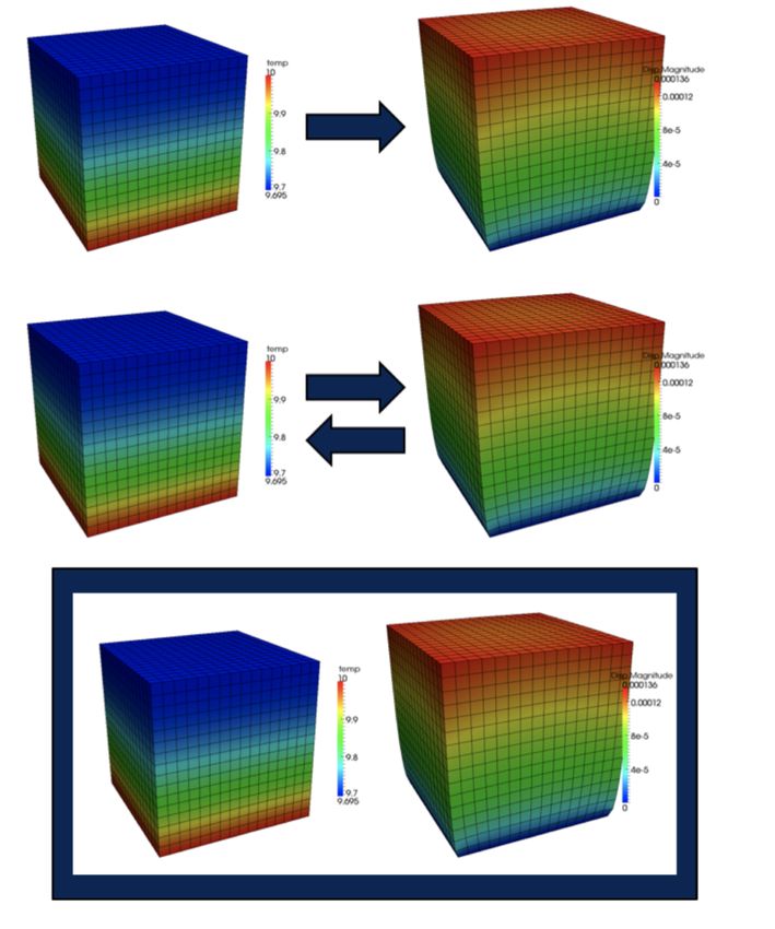
1    Introduction
The new DOE-NE “Center of Excellence for Thermal-fluids applications in Nuclear Energy"
inaugurated in April 2018 considers and researches novel new solution strategies for historically
challenging flow issues that still plague the current fleet of deployed Light Water Reactor
(LWR) nuclear reactors as well as predicting various fluid flow and fluid related issues with
advanced reactor technologies, which includes advanced Small Modular Reactor (SMR) concepts,
micro-reactors, and Advanced Reactor Concepts (ARC), utilizing coolants such as liquid metal,
chloride and fluoride salts, or gas, for accident-tolerant reactors. These new solution strategies
and algorithms will then be implemented into a modern software design methodology, using
best software quality practices, and then delivering “validated” NQA-1 level software to the
nuclear power community. Ultimately, this goal requires a facility where a strong collaborative
environment can be established between computational scientists and scientists conducting
fluid dynamic experiments.
      The center addresses a pressing need in advanced reactor development and commercial-
ization. Advanced reactor fluid problems are currently high priority and lend themselves to
advanced modeling and simulation due to the presence of complex flow and lack of empirical
data. In fact. Advanced modeling and simulation tools are poised to play an important role:
providing deep insight, enhancing the experimental process and accelerating regulatory process.
The center supports a coherent approach, and establishes a true “front door” for engaging in-
dustry. The current approach makes it difficult for customers to engage - single-PI efforts, while
individually excellent, have been somewhat disparate, and not coordinated. CFD/Thermal-
Hydraulic Center is truly a multi-lab approach analogous to that used in the very successful
fuels M&S area of NEAMS. NEAMS and Hub Thermal-Hydraulic/CFD tools are far enough along
to warrant this approach
      Our advanced thermal-fluids research and development approach synergistically combines
three natural, though overlapping, length and time scales in a hierarchical multi-scale approach
to avoid the temptation and pitfalls of attempting to develop a single “solve all” algorithm for
physical fluid flow problems that will span 109 in spatial and temporal scales. A more tractable
approach is grouping physics with similar multi-scale requirements into a common algorithm,
developing separate software applications to address the separate scales, and then coupling
the applications where appropriate. This multi-scale modeling and simulation “template” has
proven to be highly successful in the Nuclear Energy Advanced Modeling and Simulation
(NEAMS) program to simulate the evolution of nuclear materials under irradiation. These three
overlapping thermal-hydraulic scales are defined across all reactor concepts as:

    • Lower Length Scale. The Lower Length Scale will focus upon resolving the high-
      resolution physics associated with single and multi-phase, highly turbulent conjugate heat
      transfer (CHT) with highly resolved thermal boundary layers (heat flux).

    • Engineering Length scale. The Engineering Length Scale will integrate coarse mesh
      approaches for homogenized multi-dimensional CHT, such as those found in gas-cooled
      pebble-bed reactors, or three-dimensional sub-channel capabilities tightly coupled to
      nuclear fuels performance.

                                                1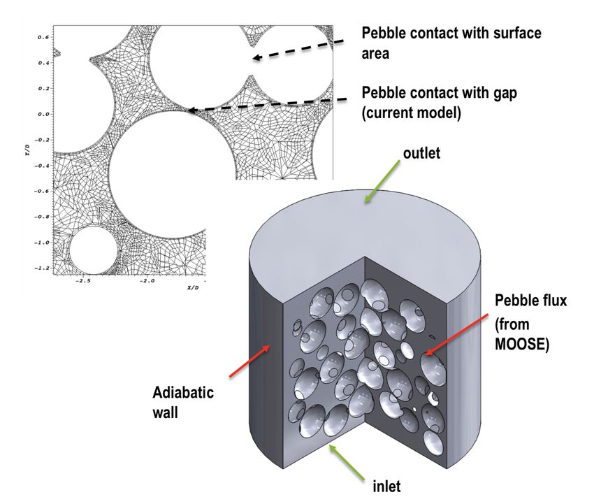
• System Scale. System Scale analysis for nuclear reactors is composed of one-dimensional
     fluid flow pipe networks and zero-dimensional system components. These classes of
     algorithms and corresponding approaches are basically reduced order models (ROM) of
     the more complex scales and allow for more efficient calculations. These reduced order
     systems rely heavily on empirical correlations or models, as many of the flow features
     and phenomena are no longer resolved.

      The demonstrate the multi-scale philosophy of the center we focus first on Flouride Cooled
High Temperature Reactors (FHRs), and in particular on Berkeley’s PB-FHR design Mark-I
design [1]. The Fluoride salt cooled High temperature Reactor (FHR) is a class of advanced
nuclear reactors that combine the robust coated particle fuel form from high temperature gas
cooled reactors, direct reactor auxiliary cooling system (DRACS) passive decay removal of liquid
metal fast reactors, and the transparent, high volumetric heat capacitance liquid fluoride salt
working fluids - Flibe - from molten salt reactors. This combination of fuel and coolant enables
FHRs to operate in a high-temperature low-pressure design space that has beneficial safety and
economic implications. In 2012, UC Berkeley was charged with developing a pre-conceptual
design of a commercial prototype FHR - the Pebble Bed- Fluoride Salt Cooled High Temperature
Reactor (PB-FHR). The Mark 1 design of the PB-FHR (Mk1 PB-FHR) is 236 MWt Flibe cooled
pebble bed nuclear heat source that drives an open-air Brayton combine-cycle power conversion
system. The PB-FHR’s pebble bed consists of a enriched uranium fuel core surrounded by an
inert graphite pebble reflector that shields the outer solid graphite reflector, core barrel and
reactor vessel. The fuel reaches an average burnup of 178000 MWt-d/MT. The Mk1 PB-FHR
exhibits strong negative temperature reactivity feedback from the fuel, graphite moderator and
the Flibe coolant but a small positive temperature reactivity feedback of the inner reflector and
from the outer graphite pebble reflector [2].
      Pebble bed reactors are in a sense the poster child for the sort of analysis described above.
FHR pebble beds in particular are comprised of hundreds of thousands of pebbles [1], and
a fine, CFD-grade detailed description of the flow field through these pebbles for an entire
reactor core is not achievable with current simulation technology. However simple porous
media approximations are often incapable of capturing key details of the flow field such as
the wall channeling effect due to the change in porosity in the proximity of the vessel walls.
Advanced formulations for the "engineering scale" have the potential to address these issues
but data from finer scale simulations is needed to build closure relationships. Pronghorn is the
platform of the center of excellence for engineering scale thermal-fluids simulations [3]. Finally,
finer scale calculations are needed to establish local temperature peaking and fuel temperatures.
     An overall multi-physics strategy for FHR simulation might look like in Figure 1. SAM, the
system analysis tool for systems analysis of advanced reactors with coolants in the liquid phase,
drives the simulation of the engineering scale tools (Pronghorn and Rattlesnake/Mammoth).
The lower length-scale tools can be run concurrently to provide dynamic closures for the
engineering scale or offline to produce correlations (which would be more likely). The lower
lenghtscale simulator comprises neutronics (OpenMC), thermal-fluids (Nek5000) and fuel
performance (BISON). Cardinal, the new tool developed in the center of excellence for lower
length-scale simulation. This new platform tightly couples all three physics and leverages
advances in MOOSE [4] such as the MultiApp system and the concept of MOOSE-wrapped Apps.

                                                2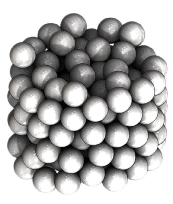
Moreover it is designed from the ground-up to scale on massively parallel architectures and
perform well on world-class super-computing architectures.

Figure 1: Diagram showing the multiscale structure of the center excellence simulator for FHRs.

      In this report we describe the design of Cardinal (Section 3), discuss initial verification
and validation especially for fluid component (Section 4) and finally describe a demo for the
application of Cardinal to an FHR (Section 5).

2     MOOSE Coupling Capability
MOOSE was originally developed for solving fully coupled systems of partial differential equa-
tions (PDEs) using fully implicit timestepping. To utilize MOOSE developers create small
C++ objects which represent their partial differential equations, boundary conditions, initial
conditions, etc. MOOSE will then coordinate PETSc and libMesh to perform a Newton solve
over all of the physics to find the solution to the multiphysics problem. While this is still the
primary way to use MOOSE, the library has also gained capability for loosely coupled solves,
Picard iteration and even coupling to external applications (such as OpenMC and Nek5000).

2.1    MultiApps and Transfers
The MultiApp system within MOOSE allows for arbitrary depth hierarchical execution of
applications in parallel [5]. As pictorialized in Figure 2 a MultiApp solve will always have a
master application. Underneath that master application can be an arbitrary number of MultiApp
objects. The MultiApp objects are containers of instances of applications and can have many
instances of that application. As an example, the master application might be a neutron transport
simulator for light-water reactors and then it could have one MultiApp representing the fuel
rods with that MultiApp having many (thousands) of instances of a fuel performance simulation
tool, one for each fuel rod. Each sub-app can, itself, also have any number of MultiApps: leading
to an arbitrarily deep tree of applications. These application instances are spread out in parallel
and all sub-apps within an individual MultiApp are executed simultaneously (given enough
computing resources).

                                                3
Figure 2: MultiApp structure. [5]

2.2   MOOSE Wrapped Apps
Critical to the current capability is that a MultiApp can hold non-MOOSE-based (“external”)
applications. This is possible using the Moose-Wrapped-App (MWA) interfaces. By creating a
few objects that wrap an external app and present it to MOOSE as a MOOSE-based application
that external application can then be placed into any point in the hierarchy. For the current
effort OpenMC and Nek5000 were both wrapped in the MWA interfaces, allowing them to
participate in a MultiApp solve. For each application the following interfaces were developed:

   • ExternalApp: Derives from MooseAppBase and is the basic wrapper to the the code the
     MultiApp system needs.

   • ExternalProblem: Derives from Problem to implement “solve()” that calls the external
     code and create data fields.

   • ExternalMesh: Derives from MooseMesh to create a mesh that is compatible with the
     external app.

     While MultiApps create trees of executing applications, Transfers are needed move data
between them. Transfers move data only vertically, up and down the hierarchy of applications.
Many different types of transfers exist including:

   • Interpolation

   • Projection

                                              4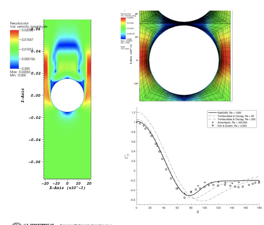
• Evaluation

   • Data-copy

   • Postprocessor transfer

   • Scalar Variable transfer

      Observation: Transfers are the difficult part. Especially getting these correct in parallel.
To combat this, the MWA system utilizes an “ExternalMesh”... it’s a MooseMesh mesh... that is
created to be extremely compatible with the third party application. Fields/values can then
be easily moved to the ExternalProblem (fields) that uses the ExternalMesh. –Built-in MOOSE
Transfers can be used to communicate those values with any other MOOSE/Non-MOOSE
application in the MultiApp hierarchy. A schematic describing the solution transfer is shown in
Figure 3.

                                  Figure 3: Solution transfer.

2.3    Coupling
MOOSE provides the ability to solve for coupled physics in three primary ways:

   • Loosely-Coupled: each physics solved with a separate linear/nonlinear solve. Data
     exchange once per timestep (typically).

   • Tightly-Coupled / Picard: each physics solved with a separate linear/nonlinear solve.
     Data is exchanged and physics re-solved until “convergence”.

   • Fully-Coupled: all physics solved for in one linear/nonlinear solve.

     These three options are depicted in Figure 4. The top coupling represents a one-way,
loose coupling where each timestep one physics is solved and the solution is passed to the
next physics solver. The second physics is then solved and time marches forward. The second
coupling utilizes “Picard” iteration to converge the two physics within each timestep. The final

                                                5
coupling method, the one originally utilized by MOOSE, is “full” coupling: all PDEs within the
system are solved simultaneously, resulting in a completely converged solution within one solve.
While fully coupled simulation has many advantages when physics are very interdependent,
it can be overly burdensome for more loosely-coupled physical systems. Therefore, utilization
of the MultiApp and Transfer systems for loose-coupling and Picard iteration can be useful for
multiscale solves, solves involving multiple timescales and solves utilizing external applications.
The Cardinal application developed for lower length scale simulation of FHRs utilizes MultiApps
for just this purpose: coupling Nek5000, OpenMC and BISON.
Figure 4: MOOSE coupling strategies. Top: loose, Middle: Picard, Bottom: full.
3 Cardinal
When utilizing MOOSE to couple multiple disparate codes together a new MOOSE-based
application must be created which compiles all of the codes into one executable. For the present
6study that code is named “Cardinal” and combines BISON, OpenMC and Nek5000 to achieve
high-fidelity simulation of FHR reactors.
3.1 Build system
In any multiphysics coupling project with a large number of dependent libraries, ensuring
consistent compilation and linking can be a challenge. Throughout Cardinal, we rely on PETSc
to detect system-dependent configuration information and to install as many third-party libraries
as possible (Figure 5). BISON, MOOSE, and libMesh already rely on PETSc, and they are built
as usual. For standalone OpenMC and Nek5000, PETSc is not a dependency; but in Cardinal,
OpenMC and Nek5000 use PETSc for two purposes:
1. PETSc is used to install HDF5 and BLAS/LAPACK, which are dependencies of OpenMC
and Nek5000.
2. The configuration info discovered by PETSc is passed to the build systems of OpenMC
and Nek5000. This is done through header files that PETSc generates specifically for this
purpose.
Hence, after installing PETSc and libMesh, Cardinal can be built in one step.
Figure 5: Diagram describing the build system of Cardinal.
3.2 OpenMC and related API
OpenMC is a Monte Carlo particle transport simulation code focused on neutron criticality
calculations. It is capable of simulating 3D models based on constructive solid geometry with
second-order surfaces. OpenMC supports either continuous-energy or multi-group transport.
The continuous-energy particle interaction data is based on a native HDF5 format that can
be generated from ACE files used by the MCNP and Serpent Monte Carlo codes. Additionally,
OpenMC can use multipole cross-section data for temperature feedback calculations (as in
7Cardinal). OpenMC uses hybrid MPI/OpenMP parallelism and shows near-linear scaling to over
100,000 processors on leadership-class supercomputers. It is open source and distributed under
the MIT license, which allows redistribution, sublicensing, and commercialization of derived
software.
For library developers, libopenmc provides a well-documented C API for online interoper-
ability with other apps. Though OpenMC and libopenmc themselves are written in C++, having
a C-only API allows a wide range of other apps to link to libopenmc, including a rich end-user
Python API distributed with OpenMC and including Cardinal. For end-users, the OpenMC
Python API uses a combination of libopenmc and NumPy for constructing models, generating
multigroup cross sections, visualizing results, running simulations, etc. For Cardinal, we use
the C API to start and stop the simulation at various levels (including the overall simulation
and individual batches) and for accessing underlying data structures (such as cell, material,
and tally data) during online coupling.
3.2.1 OpenMC Data Representation
Geometry Representation Like several other MC transport simulations (such as MCNP),
OpenMC uses constructive solid geometry (CSG) to build models in Euclidean space. Volumes
called half-spaces are bounded by quadratic surfaces, which are defined by parameterized
equations, not gridpoints. A given surface defines a positive and negative half-space, and
boolean combinations (intersections, unions, and differences) of these half-spaces can form
arbitrarily complex volumes. In OpenMC, a boolean combination of arbitrarily-many half spaces
describes a volume called a cell. Figure 6 shows a simple example where a cell (in blue) is
formed by the intersection of half-spaces defined by an ellipse and two infinite lines. The same
principle is used in 3D with ellipsoids, infinite planes, infinite cylinders, etc.
Figure 6: CSG simple.
Material Representation In OpenMC, each cell contains one or more materials; each material,
in turn, contains information about nuclide identities, nuclide atom densities, and overall
material density. Each cell also contains temperature information; note that temperature
information is not associated with the material itself.
8Listing 1: Finding cells that contain pebbles in OpenMCProblem. This is a section of the
constructor.
1 for ( auto & c : _centers )
2 {
3 openmc :: Particle p {};
4 p . r () = { c (0) , c (1) , c (2)};
5 p . u () = {0. , 0. , 1.};
6 openmc :: find_cell (& p , false );
7 _cellIndices . push_back ( p . coord_ [0]. cell );
8 _cellInstances . push_back ( p . cell_instance_ );
9 }
Tally Representation In any continuous-energy Monte Carlo simulation, a tally can be quan-
tified according to Equation 1. A scoring function (or score) is used to estimate a physical
quantity based on particle events; this corresponds to the function f in Equation 1. A filter is a
region of phase space in which events are scored; this corresponds to the limits of integration
in Equation 1. In OpenMC, filters are cells are different object types, even when given instances
of cells and filters share the same boundaries in Euclidean space.
Z Z Z
X= dr dΩ d E f (r, Ω, E) ψ(r, Ω, E) (1)
| {z }
| {z } scores
filters
3.2.2 Initializing OpenMC for Coupled Problem
Finding Cells that Contain Pebbles There have been previous efforts [6] coupling OpenMC
to MOOSE for LWR applications. However, the current effort takes a new approach: utilizing
MOOSE-Wrapped-Apps and is specialized for the PBR problem. To transfer temperature from
BISON to OpenMC, we must update the temperature of an OpenMC cell, which in turn updates
the temperature of each material in the cell. The OpenMC C API already provides a function to
accomplish this: openmc_cell_set_temperature, which takes a cell ID and a temperature.
To use this functionality, Cardinal must know a mapping from BISON’s pebble regions to the
relevant OpenMC cells.
This mapping is discovered in the constructor of OpenMCProblem, as shown in Listing 1.
_centers contains coordinates for all the pebble centers; it is provided in the Cardinal input
file and is owned by Cardinal, not OpenMC. For every center, a dummy particle (i.e. neutron) is
created from OpenMC’s existing Particle class, and that particle is assigned the coordinates
of the pebble center (the velocity is not used). We use a dummy Particle in order to leverage
OpenMC’s existing find_cell function, which is used in OpenMC’s particle tracking algorithm
to locate the cell that contains a given particle. After locating this cell, its ID is stored in
_cellIndices a sequence owned by Cardinal.
9Listing 2: Iniitiazing filter for pebbles in textttOpenMCProblem. This is a section of the
constructor.
1 for ( auto & c : _centers )
2 {
3 _filter - > cells_ = _cellIndices ;
4 _filter - > n_bins_ = _filter - > cells_ . size ();
5 for ( int i = 0; i < _filter - > cells_ . size (); ++ i )
6 {
7 _filter - > map_ [ _filter - > cells_ [ i ]] = i ;
8 }
9 }
Listing 3: Tranferring temperature from BISON to OpenMC in
OpenMCProblem::syncSolutions
1 auto & average_temp = getUserObject < NearestPointReceiver >( " average_temp " );
2 for ( int i =0; i < _cellIndices . size (); ++ i )
3 {
4 double T = average_temp . spatialValue ( _centers [ i ]);
5 o p e n m c _ c e l l _ s e t _ t e m p e r a t u r e ( _cellIndices [ i ] ,
6 T , &( _cellInstances [ i ]));
7 }
Initializing Tallies To transfer a heat source term from OpenMC to BISON, we must initialize
tallies that include a filter containing the pebbles and a scoring functions for kappa-fission.
This also handled in the constructor of OpenMCProblem. Initializing the filter is shown in in
Listing 2. After creating a list of cell IDs that correspond to the pebbles (_cellIndices, as
described above), we use those cells to define a spatial region for a filter; we do so by creating a
CellFilter, which is already provided by OpenMC. In Listing 2, _filter points to an existing
instance of a CellFilter, and we update its state by using the information that we discovered
from _cellIndices.
Initializing the scoring function and the final tally object is easily handled by existing
OpenMC API functions. It is not described here.
3.2.3 OpenMC Coupling Mechanics
Temperature Transfer from BISON to OpenMC After the onus of of discovering the cor-
rect cell indices, transferring temperatures to OpenMC is relatively simple. We rely on the
existing openmc_cell_set_temperature function from the OpenMC C API, which sets the
temperature of every material in a given cell. Listing 3 shows how this function is used in
OpenMCProblem::syncSolutions. The two sequences _cellIndices and _centers con-
tain the OpenMC cell IDs and spatial coordinates associated with all the pebbles, respectively.
For each cell, BISON gets an average temperature based on the spatial coordinate, and OpenMC
sets the temperature based on cell ID.
10Listing 4: Tranferring heat source from BISON to OpenMC.
1 xt :: xtensor < double , 1 > OpenMCProblem :: heat_source ()
2 { // heat is energy production in [ J / source ]
3 int m = _tally - > n_realizations_ ;
4 auto meanValue = xt :: view ( _tally - > results_ , xt :: all () , 0 , openmc :: RESULT_SUM );
5 xt :: xtensor < double , 1 > heat = JOULE_PER_EV * meanValue / m ;
6
7 // heat is converted to W
8 double totalHeat = xt :: sum ( heat )();
9 for ( int i = 0; i < _cellIndices . size (); ++ i )
10 {
11 double V = _volumes [ i ];
12 heat ( i ) *= _power / ( totalHeat * V );
13 }
14 return heat ;
15 }
Heat Source Transfer from OpenMC to BISON After initializing the kappa-fission tallies, it
is also relatively simple to return the heat source terms. This is implemented in the member
function OpenMCProblem::heat_source, which returns a sequence of heat values, one per
each pebble (Listing 4. The ordering of the sequence is the same as the other sequences used in
pebble-wise solution transfers, such as _centers and _cellIndices. The type of the sequence
is an xtensor from the xtensor library, a header-only library that allows high-level vector
operations with delayed execution. xtensor is used extensively in OpenMC and is be used in
Cardinal to handle arrays returned by OpenMC. After calling OpenMCProblem::heat_source,
the caller then sets the heat values in BISON.
temperature
3.3 Nek5000 and related API
Nek5000 (1999 Gordon Bell and 2016 R&D 100 award winning code) is an open-source
simulation-software package that delivers highly accurate solutions for a wide range of scientific
applications including fluid flow, thermal convection, combustion, and magnetohydrodynamics.
It features state-of-the-art, scalable, high-order algorithms that are fast and efficient on platforms
ranging from laptops to the DOE leadership computing facilities. (http://nek5000.mcs.anl.gov)
Significant applications of Nek5000 include DOE scientific computing mission areas (reac-
tor, combustion, ocean, wind, etc.) with over 350 users in academia, laboratories, and industry.
Its central role in other DOE projects includes ECP (CEED, ExaSMR, Urban, Combustion), PSSAP-
II, NEAMS, NE High-Impact Project (HIP) and INL-ANL Center for Thermal Fluid Applications
in Nuclear Energy.
Active users of Nek5000 are industrial firms AREVA, Westinghouse, TerraPower, NRG
(Energy Research Centre of the Netherlands), and BOSCH, and universities ETH Zurich, KTH
Royal Institute of Technology, ENSAM (Paris), Texas A&M, University of Miami, University
of Florida, University of Maryland, Baltimore County, and the University of Illinois Urbana
11Champaign.
In Nek5000 ([7]) the domain is decomposed globally into smaller domains (elements),
which are assumed to be curvilinear hexahedra (brick meshes) that conform to the domain
boundaries. Locally, functions within each element are expanded according to a polynomial
expansion and operators are cast in tensor-product form. The pressure can be solved at the same
polynomial order of the velocity N (PN − PN formulation) or at lower order N − 2 (PN − PN −2
formulation). We note that Nek5000 employs only pure hexahedral non-conformal meshes.
While this somewhat limits the application of the code, recent advances have allowed to apply
Nek5000 to very complex geometries using a text-to-hex technique - [8].
Temporal discretization is based on a high-order splitting that is third-order accurate in
time and reduces the coupled velocity-pressure Stokes problem to four independent solves per
timestep: one for each velocity component and one for the pressure. The velocity problems are
diagonally dominant and thus easily solved by using Jacobi preconditioned conjugate gradient
iteration. Two time-stepping schemes, both up to third order, are available: BDF and OIFS -
[9]. The pressure substep requires a Poisson solver at each step, which is performed through
multigrid-preconditioned GMRES iteration coupled with temporal projection to find an optimal
initial guess.
Particularly important components of Nek5000 are its scalable coarse-grid solvers that are
central to parallel performance. For both weak scaling and strong scaling using Algebraic Multi
Grid (AMG) for the coarse-grid solve is essential above 250,000 elements. Nek5000 employs
a pure MPI parallel implementation. An extensive discussion of the scalability of Nek5000 is
provided in [10]. An extension to GPU platforms is underway [11].
The coupling for Nek5000 to MOOSE is rather simple:
• nek_pointscloud defines a points cloud with the GLL points corresponding to the surface
mesh (corresponding to N = 2 or N = 1). The points are used by MOOSE to define a
mapping, as described in Section 2.1.
• A set of routines are then defined for solution transfer. nek_interpolation extracts the tem-
perature on the Nek5000 mesh and loads it into the points cloud in MOOSE. flux_reconstruction
is used to load flux data from the points cloud and reconstruct an arbitrary order N sur-
face field for the heat flux. At present both functions construct a full low order complete
surface mesh on each processor, but that will be updated in a future version of Cardinal
to improve scalability. We note that even with a relatively large problem like the demo
problem discussed in this report, the memory footprint and computational cost of the
solution transfer is not significant compared to the physics solves.
• Finally a set of routines for time stepping are defined: nek_initstep performs an initial
time-step evaluation, nek_step performs a Picard sub-step and finally nek_finalizestep
completes the time-step.
123.4 BISON
BISON is a MOOSE-based [4] nuclear fuel simulation tool primarily developed at Idaho National
Laboratory. BISON is capable of performing high-fidelity, finite-element, simulation of various
fuel forms including, light-water reactor fuel rods, TRISO fuel particles, and plate fuel. MOOSE
allows BISON to solve for many coupled physics including heat-conduction, solid-mechanics,
burnup, material evolution, plasticity, creep, fracture, fission gas buildup, gap heat conduction
and neutron embrittlement. In addition, BISON uses MOOSE to perform these coupled sim-
ulations within an implicit solution scheme allowing for long timesteps and high-order time
integration necessary for simulation of operating reactors.
BISON is a high-fidelity tool that has been developed to achieve predictive capability. It has
undergone rigorous assessment testing and verification analysis to ensure accurate simulation.
Further, BISON is developed using a rigorous V&V plan. This is in addition to building on a
high pedigree of software quality practices employed by the MOOSE Framework itself which
satisfy the United States NQA1 software quality requirements.
3.5 Cardinal Coupling Strategy
Cardinal utilizes the MOOSE MultiApp capability to place each of the applications to be coupled
within a hierarchical tree-based structure as shown in Figure 7. This structure was chosen
based on how tightly coupled the physics are. BISON and Nek5000 form one branch due to the
instantaneous feedback between the conjugate heat transfer and the pebble temperature. The
Nek5000 solution provides the temperature boundary condition on the exterior of each pebble
while BISON returns the heat flux at each point around the pebble to Nek5000. Another benefit
of having BISON and Nek5000 on their own branch is the way it impacts timestepping. Within
the MultiApp setup shown in Figure 7 the branch containing BISON and Nek5000 can take
many small timesteps, and even iterate between BISON and Nek5000 within a timestep, without
needing to re-solve OpenMC. This greatly increases the runtime speed of the application.
OpenMC is then separate from the other two. It receives fuel/pebble temperatures from
BISON and returns a heat source which is transferred down to BISON. OpenMC is currently
solving for steady state neutronics and can therefore take larger “timesteps” compared to
BISON and Nek5000 (which are both performing transient heat conduction and CFD solves
respectively). The flexibility of the MOOSE MultiApp system allows for just such a setup.
4 Verification and Validation
In this section we discuss work conducted as part of this work to verify and validate Cardinal.
This work is obviously preliminary and it was primarily conducted as part of development. The
verification work was focused on the solution transfer and the basic coupling mechanism. The
validation efforts have been involved on the single physics. Future work will expand on these
efforts with the goal of improving the overall trustworthiness of Cardinal.
13Figure 7: Diagram showing the current design of Cardinal.
4.1 Simple verification cases
In order to verify the fluid flow model and the solution transfer we have devised two cases
including a single pebble and a two pebble case. The Nek5000-MOOSE coupling was verified
to yield the same results as stand-alone Nek5000 conjugate heat transfer results. We note that
work in Cardinal was based on previous work conducted on Nek5000-MOOSE coupling [12].
The single pebble (Figure 15) and two pebble (Figure 17) were also used to verify the OpenMC
and BISON coupling. For instance the neutronics results showed a clear bias between pebbles
and a tilt induced by the temperature gradient.
4.2 Validation
The use of BISON to simulate TRISO particles is well documented in the literature [13] and
these efforts have received renewed attention. This previous effort focused on high-fidelity,
three-dimensional treatment of the TRISO particles themselves such as in Figure 10. For this
work BISON will be primarily employed in two main ways: solution of the "homogeneous"
pebble temperature distribution and a "microstructure" solve utilizing a one-dimension spherical-
symmetry solution for representative TRISO particles within each pebble. The three-dimensional
pebble simulation will receive a volumetric heat generation rate from OpenMC and boundary
conditions from the flow-field generated by Nek5000. The embedded TRISO particle simulations
will be utilized to find accurate fuel-kernel temperature distributions within each pebble.
In the following we focus primarily on the fluid flow validation. OpenMC validation for
pebble beds will be the focus of future work.
14Figure 8: Verification test - Single pebble, fluid mesh and comparison with experiment.
Selected results from the single pebble case were compared with results from experimental
and computational studies carried out by using a similar geometries [14]. A well quantified
quantity for flow over a single-sphere is the averaged stream- wise velocity along the domain
axial center line. Figure 17 compares our result with completed numerical results. The figure
shows the profile generated from DNS data in [15] at Re = 3, 700 and shows the downstream
location ()z/D) and magnitude of the maximum recirculation (i.e. negative streamwise)
velocity for LES and DES data generated in [16] at Re = 10, 000. One can see that for increasing
Reynolds number, the magnitude of the recirculation velocity increases, while the downstream
distance from the sphere where this maximum occurs, decreases. We do not quantify the specific
dependence of this trend on the Reynolds number here, but our result to be consistent with the
literature.
Over the past several years NEAMS has dedicated several efforts to the modeling and
simulation of the detailed flow in a pebble bed. For instance, Fick et al. [17] performed a
complete Direct Numerical Simulation of pebble bed flow. Complete statistical data was obtained
from this DNS study, with an investigation of low-frequency temporal instabilities. However,
Fick’s study [17] used a structured pebble bed, which limits its application. Nonetheless it
15Figure 9: Verification test - Two pebbles.
Outer Pyrolytic Carbon
Silicon Carbide
Inner Pyrolytic Carbon
Fuel Kernel
Porous Carbon Buffer
Figure 10: Schematic and solution showing a high-fidelity BISON simulation of a TRISO particle
from [13].
was compared against other available DNS data and proved Nek5000 can deliver high quality
simulation data for pebble beds.
A more recent study aimed at simulating the flow in a random pebble bed [8]. This
random pebble bed geometry was obtained from an experiment conducted by Nguyen et al
[18]. However, only a small section of the whole domain from the experiment was studied.
A picture of the experimental facility is shown in Figure 11, while a snapshot of the PIV field
examined is shown in Figure 12.
To create pure hexahedral mesh for random pebble bed is very challenge if using tradition
blocking method. However, with tet-to-hex meshing method, we could create pure hexahedral
mesh for this geometry. To reduce total elements number, chamfers are created at pebble-pebble
interaction. As we discussed, the computational domain is only a small section of the whole
16experimental domain, therefore we applied periodic boundary condition at inlet/outlet to mimic
the upstream/downstream. Figure 13 shows the instantaneous velocity field at cross sections of
the random pebble bed, as well as the near wall mesh at pebble surface. In Figure 13 , the flow
field is very complex due to randomly distributed pebble.
Despite the complexity of the geometry of the geometry the computational results com-
pared favorably against the experimental data as shown in Figure 14. A more detailed compari-
son will be discussed in a future journal publication.
Figure 11: TAMU experiment - Picture of the facility.
5 Demonstration simulation
In this section we describe the demonstration simulations for the FHR demonstration problem.
We choose to use the same pebble distribution of the TAMU experiment discussed in Section 4.
17Figure 12: TAMU experiment - PIV snapshot.
The pebbles and the geometry are rescaled to match dimensions proposed for FHR pebble
reactors (i.e., pebbles are 3 cm in diameter). Figure 15 shows the pebble distribution for the
demonstration problem. The coolant chosen for the demonstration is Flibe. We also assume a
power load per pebble consistent with the PB-FHR design for a total of 146 kW. Given the small
section The mass flow rate is artificially lowered to give an average temperature difference
across of 20 C.
5.1 Numerical Practices
In the following we discuss numerical practices for the demonstration problem.
5.1.1 Pebble Model for OpenMC
For this demonstrations, the sizes and composition of the TRISO particles were based on TRISO
manufactured by Phillips et. al at INL [19]. Though these particles were developed for the
Advanced Gas Reactor (AGR) fuel, particles with the same specifications are used for FHR test
reactors and computations benchmarks [1]. The sizes and compositions of the pebbles were
taken from the “Mark 1” FHR reactor constructed at UC Berkeley [1]. Tables 1, 2, 3, and 4 show
these specifications.
The resultant OpenMC model is shown in Figure 16; the figure shows a close-up of a 2D
slice of one pebble. In this demo, the TRISO particles are packed in a regular, square lattice
18Fuel Region Total mass density = 10.5 g/cm3
Isotope Relative atom density
U234 0.0143
U235 7.10
U238 28.3
C 14.1
O 50.5
Buffer Layer Total mass density = 1.0 g/cm3
C 100
PyC Inner Layer Total mass density = 1.87 g/cm3
C 100
SiC Layer Total mass density = 3.2 g/cm3
C 50.0
Si 50.0
PyC Outer Layer Total mass density = 1.6 g/cm3
C 100
Table 1: TRIO Composition
Inner Graphite Core Total mass density = 1.59 g/cm3
Isotope Relative atom density
C 100
Outer Graphite Shell Total mass density = 1.74 g/cm3
C 100
Table 2: Pebble Composition
FLiBe Total mass density = 1.97 g/cm3
Isotope Relative atom density
Li7 28.6
Li6 0.00286
Be9 14.3
F19 57.1
Table 3: Coolant Composition
19Figure 13: TAMU experiment - Simulation results. Top - cross section. Bottom - Three-
dimensional plot.
with the same overall packing fraction described by [19], rather than a randomized and/or
irregular distribution. This choice was made for for computational efficiency, since OpenMC can
apply optimizations for particle (i.e. neutron) tracking in a regular lattice. Some optimization
methods have been developed specifically for building models with TRISO particles [20], and
these will be used for future demonstrations.
20Figure 14: TAMU experiment - Comparison with experiment for selected plane.
5.1.2 Pebble Model for Nek5000
The pebble model for the Nek5000 reflects the practices used for the TAMU experiment de-
scribed in Section 4, which were validated carefully against experimental PIV data. Inlet/outlet
boundary conditions are used (Figure 17.). Unlike the TAMU experiment, here the mesh is
designed to allow a clearance between pebbles. This facilitates the coupling but it will likely be
updated in future simulations. The difference is outlined in Figure 17. The mesh comprises
approximately roughly 500,000 elements overall and it is designed to run at N = 5 for coarse
results and N = 7 for finer simulations (for a max of 256 million grid points). We assume
constant properties.
21Figure 15: Three-dimensional representation of the pebble bed used for the demonstration
problem.
TRISO Particle Dimensions
Particle Diameter 400 µm
Buffer Layer Thickness 100 µm
PyC Inner Layer Thickness 35 µm
SiC Layer Thickness 35 µm
PyC Outer Layer Thickness 35 µm
Pebble Dimensions
Pebble Diameter 30.0 mm
Inner Core Diameter 25.0 mm
Outer Shell Thickness 1.0 mm
Table 4: TRIO And Pebble Dimensions
To test various options and accelerate the development we defined four variants of the
demo problem all available in the Cardinal repository. The variants reflect the need to define
cheaper transients for testing purposes. Table 5 shows the cases: they are listed from 1 to 4 with
increasing computational cost. Restarting from an advanced restart leads to faster convergence.
Moreover, simulating the full Navier-stokes is considerably more expensive than assuming a
"frozen velocity" and solving only the advection-diffusion equation.
22Figure 16: A 2D slice of the OpenMC model of an FHR pebble. Red represents fuel, yellow
represents SiC, and blue represents graphite (where darker shades are more dense).
Figure 17: Mesh and boundary conditions for Nek5000 problem.
23Case Restart condition Solver
1 Advanced restart state Advection-Diffusion only
2 Constant temperature Advection-Diffusion only
3 Advanced restart state Full Navier-Stokes
4 Constant temperature Full Navier-Stokes
Table 5: Nek5000 cases with various solver options.
MCNP
Boundary conditions Eigenvalue
r vacuum and z vacuum 0.00357 0.000005
r vacuum and z white 0.00463 0.000005
r vacuum and z reflective 0.00448 0.000005
r reflective and z reflective 1.10405 0.00005
OpenMC
Boundary conditions Eigenvalue
r vacuum and z vacuum 0.00356 0.00001
r vacuum and z reflective 0.00451 0.00001
r reflective and z reflective 1.10749 0.00082
Table 6: Eigenvalue for OpenMC and MCNP calculations
5.1.3 Pebble Model for BISON
For the demonstration problem under consideration we consider only the conduction equation
and as such it is a relatively straightforward setup. Properties are constant and adapted from
available correlations. The mesh for a single sphere is generated and replicated at run time.
5.2 Results
In this section we report select results for the simulation campaign of the demonstration problem.
Table 6 presents a comparisons for the eigenvalue kin f computed with OpenMC and MCNP for
various boundary condition combinations. We note the strong sensitivity to the radial boundary
condition given the small size of the domain. Overall results are consistent between the two
codes.
For the coupled simulations we opt to tightly coupled Nek5000 and BISON, and loosely
couple OpenMC, given that if the OpenMC is performed at every step the computational cost
becomes excessive. We perform the OpenMC solve every 100 steps. The simulations are
performed on 2000 processors. Snapshots of the state after an initial transient are shown in
Figure 18 and Figure 19. In particular, we observe:
• The effect of the complex flow field on the surface temperature of the pebbles.
• A slight tilt in the temperature distribution in the interior of the fuel due to the outer
24temperature condition of each pebble.
• The effect of the reflective boundary conditions on the power distribution and a slight
power tilt toward the bottom due to the colder coolant.
Figure 18: Demo Results. From left to right: snapshots of temperature on surface, average
temperature in solid and average heating
Figure 19: Demo Results. Right - temperature in the solid. Left - temperature details in the
fluid.
6 Conclusions and Future Work
In this report we describe the creation of Cardinal. Cardinal provides a platform for running cou-
pled OpenMC+Nek5000+BISON. We demonstrated the application of Cardinal to an FHR demo
problem and presented a limited verification and validation case. This exercise demonstrates
25that the Moose-Wrapped-App paradigm is working well. Moreover, by wrapping OpenMC and
Nek5000 they can now be mixed and matched with any other MOOSE- based app.
Future work on Cardinal will involve a more sophisticated thermal contact treatment
between pebbles leveraging novel ideas using MOOSE constraints. We may also include more
advanced solution transfer mechanisms such as function expansion tally transfers to and from
OpenMC and to and from Nek5000. We will also work on Improving the scalability of transfers
as they rely right now on replicating a coarse surface mesh on every MPI rank. In fact we aim
to massively parallel simulations going up to the whole of Summit for quarter core simulations.
These simulations may involve asynchronous parallel execution between the physics. Finally a
multiscale approach may be employed to simulate a select number of fuel particles directly.
Acknowledgments
Argonne National Laboratory’s work was supported by the U.S. Department of Energy, Office of
Nuclear Energy, Nuclear Energy Advanced Modeling and Simulation (NEAMS), under contract
DE-AC02-06CH11357.
26References
[1] Charalampos Andreades, Anselmo T. Cisneros, Jae Keun Choi, Alexandre Y.K. Chong, Mas-
similiano Fratoni, Sea Hong, Lakshana Huddar, Kathryn Huff, David Krumwiede, Michael
R. Laufer, Madicken Munk, Raluca Scarlat, Nicolas Zweibaum, Ehud Greenspan, and
Per Peterson. Technical description of the “Mark 1” pebble-bed fluoride-salt-cooled high-
temperature reactor (PB-FHR) power plant. Technical Report UCBTH-14-002, University
of California, Berkeley, Berkeley, California, September 2014.
[2] Anselmo Tomas Cisneros. Pebble Bed Reactors Design Optimization Methods and their
Application to the Pebble Bed Fluoride Salt Cooled High Temperature Reactor (PB-FHR). PhD
thesis, UC Berkeley, 2013.
[3] Ling Zou, April J Novak, Richard C Martineau, and Hans D Gougar. Validation of
PRONGHORN with the SANA experiments. Technical Report INL/EXT-17-44085, Idaho
National Laboratory, Idaho Falls, Idaho, December 2017.
[4] Derek Gaston, Chris Newman, Glen Hansen, and Damien Lebrun-Grandie. Moose: A
parallel computational framework for coupled systems of nonlinear equations. Nucl. Eng.
Des., 239(10):1768–1778, 2009.
[5] Derek R. Gaston, Cody J. Permann, John W. Peterson, Andrew E. Slaughter, David Andrš,
Yaqi Wang, Michael P. Short, Danielle M. Perez, Michael R. Tonks, Javier Ortensi, Ling
Zou, and Richard C. Martineau. Physics-based multiscale coupling for full core nuclear
reactor simulation. Ann. Nucl. Energy, 84:45–54, 2015.
[6] Matthew Ellis, Derek Gaston, Benoit Forget, and Kord Smith. Preliminary coupling of the
Monte Carlo code OpenMC and the multiphysics object-oriented simulation environment
for analyzing Doppler feedback in Monte Carlo simulations. Nucl. Sci. Eng., 185(1):184–
193, 2017.
[7] Nek5000 Contributors. Nek5000. https://github.com/Nek5000/Nek5000, 2019.
[8] H. Yuan, E. Merzari, Y. Yu, V. Makarashvili, A. Obabko, M. Yildiz, G. Botha, and Y. Hassan.
Applying tet-to-hex meshing method to complex nuclear reactor geometries for spectral
element code. In Proceedings of the 18th International Topical Meeting on Nuclear reactor
Thermal Hydraulics, NURETH-18, August 2019. Portland, OR.
[9] Paul F Fischer. Implementation considerations for the OIFS/characteristics approach to
convection problems, 2003. https://www.mcs.anl.gov/~fischer/Nek5000/oifs.
pdf.
[10] Nicolas Offermans, Oana Marin, Michel Schanen, Jing Gong, Paul Fischer, Philipp Schlatter,
Aleks Obabko, Adam Peplinski, Maxwell Hutchinson, and Elia Merzari. On the strong
scaling of the spectral element solver Nek5000 on petascale systems. In Proceedings of the
Exascale Applications and Software Conference 2016, page 5. ACM, 2016.
27[11] E. Merzari. Toward exascale: Large eddy simulation and direct numerical simulation
of nuclear reactor flows with the spectral element method. In Proceedings of the 18th
International Topical Meeting on Nuclear reactor Thermal Hydraulics, NURETH-18, August
2019. Portland, Oregon.
[12] April Novak, Paul Romano, Brycen Wendt, Ronald Rahaman, Elia Merzari, Leslie Kerby,
Cody Permann, Richard Martineau, and Rachel N Slaybaugh. Preliminary coupling of
OpenMC and Nek5000 within the MOOSE framework. In Proceedings of PHYSOR, 2018.
[13] JD Hales, RL Williamson, SR Novascone, DM Perez, BW Spencer, and G Pastore. Multi-
dimensional multiphysics simulation of triso particle fuel. Journal of Nuclear Materials,
443(1-3):531–543, 2013.
[14] Lambert H Fick, Elia Merzari, Oana Marin, and Yassin A Hassan. Investigation of the
dynamics of incompressible flow in domains of multiple close-packed spheres. In ASME
2017 Fluids Engineering Division Summer Meeting, page V01BT12A007. American Society
of Mechanical Engineers, 2017.
[15] Ivette Rodriguez, Ricard Borell, Oriol Lehmkuhl, Carlos D Perez Segarra, and Assensi
Oliva. Direct numerical simulation of the flow over a sphere at Re = 3700. J. Fluid Mech.,
679:263–287, 2011.
[16] George S Constantinescu and Kyle D Squires. LES and DES investigations of turbulent
flow over a sphere at Re = 10,000. Flow, Turbulence and Combustion, 70(1-4):267–298,
2003.
[17] Lambert H Fick, Elia Merzari, and Yassin A Hassan. Direct numerical simulation of
pebble bed flows: Database development and investigation of low-frequency temporal
instabilities. J. Fluid. Eng., 139(5):051301, 2017.
[18] Thien Nguyen, Ethan Kappes, Stephen King, Yassin Hassan, and Victor Ugaz. Time-
resolved PIV measurements in a low-aspect ratio facility of randomly packed spheres and
flow analysis using modal decomposition. Experiments in Fluids, 59(8):127, 2018.
[19] Jeffrey A. Phillips, Scott G. Nagley, and Eric L. Shaber. Fabrication of uranium oxycarbide
kernels and compacts for HTR fuel. Nucl. Eng. Des., 251:261–281, 2012.
[20] OpenMC Contributors. Modeling TRISO Particles — OpenMC Documentation. https:
//docs.openmc.org/en/stable/examples/triso.html, 2019.
28Mathematics and Computer Science Division Argonne National Laboratory 9700 South Cass Avenue, Bldg. 240 Lemont, IL 60439 www.anl.gov
You can also read