Carbon nanostructure-based superhydrophobic surfaces and coatings
←
→
Page content transcription
If your browser does not render page correctly, please read the page content below
Nanotechnology Reviews 2021; 10: 518–571
Review Article
Viswanathan S. Saji*
Carbon nanostructure-based superhydrophobic
surfaces and coatings
https://doi.org/10.1515/ntrev-2021-0039 The research realm of superhydrophobic (SHPC) sur-
received May 26, 2021; accepted June 8, 2021 faces (water contact angle [CA] > 150°) [14–18] has enticed
Abstract: Research and development on superhydrophobic substantial scientific curiosity owed to their impending
carbon nanostructures and their nanocomposites have real-world applications [19–21]. The extreme water repel-
high industrial significance. Here, a comprehensive review lency of SHPC surfaces is credited to the confined air layer
of the topic is provided. Reported works on superhydro- at the surface/water interface [18–25]. Typically, the
phobic surfaces and coatings of carbon nanotubes, nano- superhydrophobicity (SHPY) could be achieved via
fibres, nanospheres/nanothorns/others, nanodiamond, proper optimization of the surface roughness (micro/
fullerene and their various nanocomposites with metals, nano-hierarchical surface structuring) and the surface
ceramics, and polymers are described. Superhydrophobic energy (low SE) [20,21,24]. Low sliding angle (SA < 5°)
nanostructured carbon soot, graphitic carbon, and others and contact angle hysteresis (CAH < 10°) deliver added
are also presented. The section on superhydrophobic gra- self-cleaning properties [19–21,25]. Precise fundamen-
phene is presented concisely at the end. Reports in different tals of SHPY [19–21,26–32] and details of basic surface
application areas, including anti-corrosion, anti-icing, oil wettability theories [22,23,33–35] are described elsewhere.
separation, anti-biofouling, and sensors, are discussed Carbon nanomaterials (CNMs) are typically hydro-
separately. Superoleophobic and superamphiphobic sur- phobic [10,11]. SEs of CNTs could be at the range of
faces are also discussed. 27–45.3 mJ/m2 [12]. SEs of chemically exfoliated GR and
graphene oxide (GO) have shown to be 46.7 and 62.1
Keywords: carbon nanomaterial, superhydrophobic, carbon mJ/m2, in that order, while that of normal graphite flake
nanotube, graphene, anti-corrosion, oil separation was ∼54.8 mJ/m2 [13]. The higher surface roughness,
nano/micro-hierarchical surface structures (nanoscale
CNMs and their microscale aggregates), surface reduction
processes (removal of hydrophilic surface groups), addi-
1 Introduction tional low SE treatments all could boost the hydrophobicity.
A significantly higher number of reports are available
Carbon nanostructures and their composites continued to on SHPC carbon nanostructure (CNS)-based surfaces and
attract colossal research attention, owing to their out- coatings. Hitherto, no comprehensive review is available
standing chemical, physical, mechanical, and electrical on the topic. Most of the published reviews focused on
properties [1–3]. The discovery of fullerenes in 1985 (1996 GR. Chen et al. in 2013 [36] and Wang et al. in 2015 [37]
Nobel Prize in Chemistry) [4], carbon nanotubes (CNTs) reviewed SHPC GR. Gupta et al. reviewed various CNMs in
in 1993 [5,6], and graphene (GR) in 2004 (2010 Nobel oil separation application [38]. Liu et al. [39], Khan et al.
Prize in Physics) [7,8] led to a mammoth increase of [40], and Li et al. [41] provided good accounts of photo-
research outputs in this area. The most investigated can- reduced, chemical vapour deposited, and laser-struc-
didates are CNTs and GR [2,3,9–13]. tured GR, respectively. Jishnu et al. reviewed GR-based
SHPC anti-corrosion coatings [42], whereas Sharma et al.
provided a short account of CNT-based corrosion-resis-
tant coatings [43]. Recent advances in laser-fabricated GR
surfaces have been reviewed by Ma et al. [44]. A few
* Corresponding author: Viswanathan S. Saji, Interdisciplinary
recent reviews described SHPC CNSs as a part [10,45,46].
Research Center for Advanced Materials, King Fahd University of
Petroleum & Minerals, Dhahran 31261, Saudi Arabia,
A considerably higher number of recent reports are avail-
e-mail: saji.viswanathan@kfupm.edu.sa, tel: +966-13-860-1187, able in this area. Hence, we made a systematic approach to
fax: +966-13-860-3996 comprehensively present the entire domain’s available
Open Access. © 2021 Viswanathan S. Saji, published by De Gruyter. This work is licensed under the Creative Commons Attribution 4.0
International License.
Superhydrophobic carbon nanostructures 519
information under one roof. Single and multicomponent area is oil separation, and the second most is the anti-
(with metals, ceramics, and polymers) SHPC surfaces corrosion coatings (Figure 1b and c).
and coatings based on CNTs, carbon nanofibres (CNFs),
carbon nanospheres/thorns/others, nanodiamonds, full-
erenes, nanoscale carbon soot/graphitic carbon/others,
as well as GR are presented. Due to the available reviews, 2.1 CNTs
detailed descriptions of GR-based materials were not
attempted; however, the literature carefully covered and SHPY was observed for both aligned and non-aligned
presented concisely. Four application areas, viz., anti-cor- CNT films, with and without an additional low SE compo-
rosion, oil-separation, anti-icing, and anti-biofouling, are nent/modification. Typically, composite formation with
highlighted; other applications are briefly mentioned. polymers and ceramics help overcome the long-term dur-
ability issues of SHPC CNT surfaces [47–49].
2 Carbon nanostructure-based 2.1.1 Aligned carbon nanotube (ACNT) arrays
superhydrophobic surfaces
ACNTs have attracted significant research attention owing
Nearly 45% of the reports fall under GR, followed by CNTs to their unique surface topography [50,51]. The surface
(∼32%) (Figure 1a). The most investigated application roughness of vertically ACNTs (VACNTs) could be finely
Figure 1: (a) Pie chart showing the extent of works reported with different CNS-based SHPC surfaces: (1) CNTs, (2) CNFs, (3) carbon nano/
microspheres, (4) carbon nanothorn/onion/others, (5) GR, (6) nanoscale carbon soot/graphitic carbon/others, (7) nanodiamond, and (8)
fullerene. (b and c) Pie charts on works reported on (b) CNTs and (c) GR in different applications: (1) anti-corrosion, (2) oil separation, (3)
anti-icing, (4) biomedical/anti-biofouling, (5) sensor, (6) others, and (7) fabrication/mechanism (no specific application studies). Both
single and multi-component (with metals/ceramics/polymers) SHPC surfaces considered. Works reported on SOPC and SAPC systems are
also included (Source: SciFinder/Various sources).
520 Viswanathan S. Saji
tuned by adjusting their diameter and interspace distance corresponding CNTs grown on planar Si wafer lose the
[52–57]. Until 2006, the SHPY was reported for VACNTs SHPY once exposed to tiny water droplets [68]. Aligned
only [58–62]. crystalline carboxyl-functionalized MWCNTs grown on SiC
Chemical vapour deposition (CVD)-fabricated 3D ani- cellular skeleton (ceramic pillars with ∼700 μm porous
sotropic ACNT film on the patterned Si template (with microchannels and ∼250 μm diameter) by catalyst CVD dis-
quadrate pillar array) displayed both SHPY and superhy- played long-term stability against water-droplet ingres-
drophilicity (SHLY) at varying structural parameters of sion [69].
the template. The SHPY of the as-formed CNT arrays To enhance the surface durability against water-
was attributed to the vertically aligned organization and ingression and surface tension-assisted tie-up, various
the copious fraction of trapped air. The as-formed arrays surface treatments for SHPC VACNT forests were investi-
with pillar space of 20, 15, 10, and 6 µm have shown CAs of gated. In an earlier study, Journet et al. proposed a thiol
∼22.1°, 142.9°, 25.5°, and 10°, respectively. The corre- modification for CVD-grown (planar Si substrate, 750°C)
sponding CAs of the surfaces after a vinyltrimethoxysilane CNT forests. The surface first covered with a thin sputtered
modification were 21.2°, 153.3°, 27.2°, and 20.8° [63]. Lau Au layer and subsequently, thiol-modified (CA ∼ 164 ± 2°)
et al. showed that a thin layer of polytetrafluoroethylene [70]. Studies on liquid flow slippage over SHPC thiol-
(PTFE) coating on VACNT forest could avoid the potential modified VACNT forests (CVD, microchannels) disclosed
droplet seeping into the CNT’s voids down to the micro- that the slip lengths varied linearly with the lateral
scopic level and created a stable SHPC surface with roughness scale [71]. Santhagopalan et al. showed that
advancing and receding CAs of 170° and 160°, respec- a high-voltage electrophoretic deposited (EPD) and low
tively. CVD was employed to deposit both the CNT array SE PTFE-coated VACNT film displayed a CA of ∼160° [72].
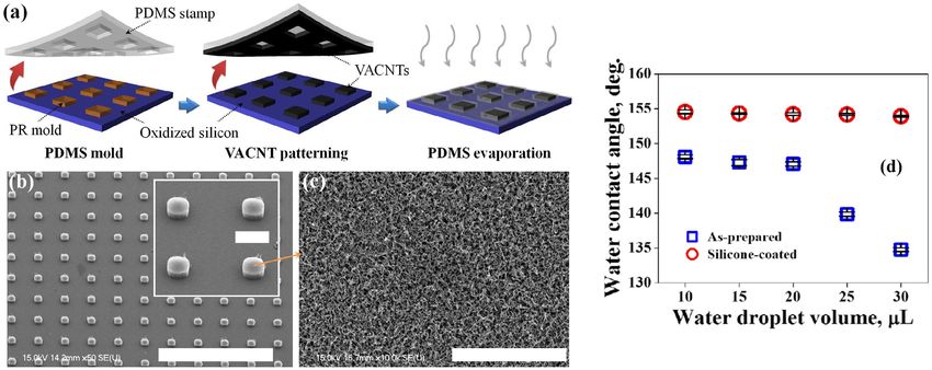
and the PTFE coating [52]. Wang et al. studied SHPY Jeong et al. employed a simple contact transfer micro-
under dynamic conditions and observed that the droplet patterning technique to fabricate VACNT micro-pillar
bounces off several times on an array with a CA of 163°, arrays with different inter-pillar spacings extending
whereas for an array with a CA of 140°, the drop remained from 45 to 160 μm (width ∼65 μm) (Figure 2a–c). A thin
pinned [56]. For microfluidics applications, Qu et al. hydrophobic CVD silicone layer coating was helpful to
reported a variety of SHPC ordered CNT polyhedron struc- enhance the SHPC robustness, even under pressurized
tures with a CA of up to 162° via CVD (∼850°C) inside the conditions. The CAs of the as-fabricated VACNT arrays
microchannels of patterned SiO2 substrate, where the (without silicon coating) displayed a steady decrease,
confined space was decisive in the realization of poly- whereas the CAs of silicone-coated arrays were stable
hedral structures with hexa/hepta/octagonal cross-sec- regardless of the droplet volume (Figure 2d). The CAs of
tions. CNT’s self-ordering and the high-temperature the VACNTs gradually increased with the increase of the
deposition yielded SHPY where no low SE treatment inter-pillar spacing, reaching a maximum for 160 μm
was used [64]. Lu et al. showed that micropatterning of spaced sample (CA of 168 ± 0.3°, CAH of 2.64 ± 0.4°,
MWCNTs enhances hydrophobicity. They employed a and SA ∼ 5°) [73]. Sojoudi et al. have shown that the
laser pruning technique to make SHPC parallel micro- top-gathering and elastocapillary densification of the
wall arrays from VA-MWCNTs. The optimal SHPC surface porous CNTs could be prohibited by conformal deposi-
consisted of micro-wall arrays with a width of ∼13 μm and tion (CVD, 80°C) of an ultrathin film of poly(1H,1H,2H,2H-
a channel width of ∼50 μm [65]. Ramos et al. showed that perfluorodecylacrylate) [74]. Yung et al. investigated CF4
CO2 laser treatment could re-establish superhydrophilic plasma modification on VACNTs using CVD (800°C) to
(SHPL) VACNT surface to SHPC by decreasing the polar fabricate ultra-low reflectance SHPC surface [75].
components (oxygen terminations on the surface) due to Aria and Gharib showed that SHPC CNT arrays could
the high local heating rate. The microwave (MW) plasma be made by exposing hydrophilic CNT arrays to a suitable
CVD-deposited VACNT film was initially pretreated with vacuum annealing (via removal of oxygenated hydro-
oxygen plasma to convert to SHPL and then subjected to philic groups). Alternate vacuum pyrolysis and UV/ozone
the laser treatment [66]. Lepore et al. compared SHPY of treatments allowed easy switching of ACNT arrays between
cabbage leaf and CVD-grown VACNT carpet and showed SHPY and SHLY [76]. The authors in a later work studied
that cabbage-like morphologies could be helpful to achieve droplet-impact dynamics of SHPC CNT arrays and revealed
better SHPY for nanofluidic applications [67]. Hierarch- that no droplet pinning happened during a wide range of
ical CNT assembly fabricated on a Si micro-pillar array critical Weber number (Wn) [57]. Babu et al. showed that
displayed slippery SHPY (CA of ∼155° and SA of ∼5°) SHPC VACNTs could be fabricated via water-assisted CVD
with excellent durability against water ingression. The by a regrowth process (by a second-time catalyst-assisted
Superhydrophobic carbon nanostructures 521 Figure 2: (a) Scheme showing fabrication steps of hierarchical VACNT SHPC surface. (b) SEM image of the CNT micro-pillar arrays. Scale bars correspond to 1 mm and 100 µm (inset). (c) Enlarged view of the pillar top. (d) CA variation with water-droplet volume [73]. Reproduced with permission from ref. [73]; © 2014 Elsevier Ltd. deposition). The regrown CNTs displayed high CA (due to higher temperature (950°C) processed sample was attrib- increased surface roughness); however, the CAH was uted to the widened outer tube diameters [79]. ∼60° (attributed to the surface hydrophilic groups). A Several studies reported composites of ACNTs with subsequent vacuum annealing (350°C) or polydimethyl- other CNSs. Maziar et al. synthesized self-assembled ACNT/ siloxane (PDMS) modification could further increase the carbon-nanosphere hybrid film. Here, the ACNT array CA with a significant CAH reduction (Figure 3). Both the was first fabricated by CVD (800°C), and then amorphous high-temperature annealing and the low SE treatment carbon nanospheres were deposited by cathodic vacuum were helpful to eliminate the hydrophilic groups [77]. arc (negative substrate bias of 100 V). The wettability was Later, the authors confirmed a flat continuous reflecting closely related to the size of the deposited nanospheres. air layer at the VACNT surface a few moments after sub- Increasing the deposition time increased the spheres’ merging in water [78]. Hsiao et al. fabricated SHPC and size, decreased the air gaps between the CNTs, and low- self-cleaning CNT forest on a quartz surface by CVD at ered the surface hydrophobicity [80]. SHPC CNT arrays 850°C (CA ∼ 154°). The lower CA (∼115°) obtained for a capped with amorphous carbon NPs were fabricated by Figure 3: Schematic of the process. The regrowth CVD process increased the roughness of the CNT surface. Hydrophilic groups in the re- grown CNTs are removed by either vacuum annealing or silane modification (θh corresponds to CAH) [77]. Reproduced with permission from ref. [77]; © 2014 WILEY-VCH Verlag GmbH & Co. KGaA, Weinheim.
522 Viswanathan S. Saji
plasma immersion ion implantation (PII, 800°C). The CA were derived via a three-step procedure involving oxida-
of unprocessed CNT forests was ∼0°, whereas the nano- tion, cycloaddition, and silane modification. The study
composite displayed a CA of ∼180°. The excellent SHPY showed that incorporating fluorosilane-coated CNTs in
was attributed to the unique overhang structure in which polymers or textiles in small proportions could render
drops could penetrate only under a higher hydrostatic them SHPC [119]. Hsieh et al. employed catalytic CVD to
pressure [81]. Han et al. synthesized CNT forests (CVD, decorate CNTs on a carbon fabric. The resulted two-tier
800°C) and then processed them by Ar PII so that the roughness along with a spin-coated perfluoroalkyl top
graphitic sidewalls of CNTs were partly shattered and coating yielded CA and CAH of 169.5° and 4.7°, respec-
sphere-shaped amorphous carbon NPs were shaped on tively [120]. Zhang and Resasco demonstrated dramatic
top. The surface displayed a CA of ∼160° and an SA of ∼5°. changes in hydrophobicity with different types of SWCNT
Their electrowetting studies explored slippery–sticky films made on Si wafers, namely, random network (grass),
transformation with applied potentials [82]. vertically aligned (forest), and bundled (pillars). The CNT
Huang et al. demonstrated SHPC ZnO-coated CNTs pillars prepared under optimized conditions exhibited the
(CA ∼ 159°) where ZnO thin film was deposited (by best SHPY with a CA of ∼160°, which is attributed to the
cathodic vacuum arc) on CVD-made ACNTs. Contrary to typical nano/microscale surface roughness [88].
the bare CNT surface, the coated surface showed no water Sunny et al. have grown CNTs on acid-etched steel by
ingression even after an extended period [83]. A report is CVD (750°C), and subsequently, a thin layer of PDMS
available on room temperature EPD-made CNT-Ni and (0.5 g of Sylgard in 1 mL of xylene) was spin coated and
CNT-Zn. The study showed that CAs of the nanocompo- dried at 70°C (to facilitate PDMS cross-linking). The
site could be adjusted from 60° to >150° by altering the coating improved the abrasion resistance of the surface
EPD voltage from 50 V to 250–550 V. The SHPY was attrib- while the SHPY and the conductivity were unaffected
uted to the combined effect of the multi-scale roughness [127]. Li et al. described a highly flexible SHPC (CA of
and the low SE attributed to the adsorbed hydrocarbon ∼155°) carpet structure composed of long (∼300 μm),
groups [84]. roughly aligned, and pure cup-stacked CNTs synthesized
Most of these studies categorically showed that SHPC by catalytic CVD at 850°C [89]. Wang et al. developed a
VACNT arrays suffer from long-term durability issues due one-step template-free CVD approach, and the fabricated
to the potential water ingression. A subsequent low SE CNT film effectively avoided the capillary-induced liquid
surface coating or a desirable composite formation could spreading. The SHPC surface displayed excellent air
alleviate the shortcoming to the desired extent. exposure and chemical durability (Figure 4) [93]. Recently,
Yin et al. made SHPC CNT film composed of short CNT
strands via CVD at 700°C. The fraction of the water/air
2.1.2 CNTs (non-aligned) contact area was calculated to be 95.7%, demonstrating
a significant extent of the air pocket existed. The surface
Randomly laid CNT films would deliver a more accessible showed excellent durability during 4 weeks of wettability
and cost-effective method for developing SHPC coatings test and superb chemical robustness over a wider pH range
[62,85–193]. Many fabrication techniques, including CVD, (0–14) [94]. A few earlier studies attempted CNT only-coat-
vacuum filtration, spray coating, and drop coating, were ings on steel meshes by CVD [90,91].
reported. Typically, as-purchased pristine CNTs or low SE- Several works employed vacuum filtering. Wu et al.
modified CNTs are used. used a mixture of 0.1 g of MWCNTs with the desired
Xu et al. reported SHPC non-aligned CNT coating amount of stearic acid (STA) in 80 mL of deionized water.
(drop coated on glass) by using alkyl (COOC18H37)n)-mod- The mixture was further diluted with water (5 mL diluted
ified MWCNTs. The CAs of alkyl-modified, carboxylic-func- to 100 mL), CH3COOH (1 mL) was added, vacuum fil-
tionalized, and as-purchased MWCNTs were 155° (SA > 5°), trated, and dried (70°C) to obtain the SHPC MWCNT
63°, and 39°, respectively. The SHPY was attributed to hybrid [95]. A film fabricated from octadecylamine (ODA)
the double-structured surface roughness and the low SE (∼14%) functionalized MWCNTs by vacuum filtration
grafted alkyl chains [62]. Hong et al. prepared SHPC CNT (MWCNT–ODA dispersion was sieved through a filter
powder by low-pressure NF3 glow-discharge plasma. The paper, peeled off, and dried at 60°C) exhibited a CA of
fluorinated CNTs with very low SE (0.12 mJ/m2) displayed 165° and an electrical conductivity of 860 S/m [96]. Chen
CAs at the range of 153–158° for polyethylene glycol (PEG), et al. reported MWCNT/SWCNT hybrid film with a CA of
glycerol, and water. The corresponding untreated CNT 152° and an SA of 2°. CVD-made MWCNTs were ultraso-
powder was SHPL (CA ∼ 0°) [85,86]. SHPC MWCNTs nically dispersed in EtOH (25 mg/mL) and vacuum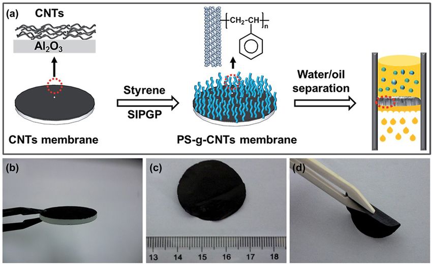
Superhydrophobic carbon nanostructures 523
Figure 4: CAs of the SHPC CNT film during (a) air (∼60% humidity) and (b) corrosive liquid exposure [93]. Reproduced with permission from
ref. [93]; © 2017 American Chemical Society.
filtrated through an SWCNT film, dried at 80°C, and water adhesion was presented by alternating heat treat-
annealed at 700°C. The MWCNTs do not detach from ment and UV illumination [102]. An extremely durable
the SWCNTs during bending or twisting studies, dis- SHPC coating (CA 153.1 ± 2° and SA < 5°) was fabricated
playing a firm hybrid structure [97]. Su et al. reported by spraying an aqueous dispersion of CNTs and perfluoro-
layer-by-layer (LbL) SHPC CNT film by vacuum-assem- alkoxy resin [131]. Yoon et al. reported a two-step process
bling multilayer carboxylated/aminated MWCNTs, fol- where CNT solution was first spray coated on stainless
lowed by transferring onto ethylene-vinyl acetate (EVA) steel (SS), and subsequently, a PTFE suspension (water-
copolymer and modifying with ODA [99]. An ultrathin based, 60% w/w PTFE) was spin coated. A coating
nanocomposite was fabricated on polyethylene via LbL annealed at 360°C displayed a CA of 154.6 ± 6° [124].
self-assembly of aminated-MWCNTs (nucleophilic) and Wang et al. reported spray-coated and pressure-proof flex-
polyacrylic acid (PAA) or Gantrez (electrophilic). Ionic ible CNT/silane coating where PDMS and as-purchased
assembly of aminated-MWCNT/PAA or covalent assembly MWCNTs were used. First, the substrate was spin
of aminated-MWCNT/Gantrez resulted in SHPY. A five- coated with a solution of 0.1 g of PDMS and 0.01 g of
times covalent LbL-deposited surface showed a CA of curing agent in 10 mL of toluene or n-hexane. Subse-
165° and an SA of >5°, whereas the corresponding ionic quently, MWCNT/EtOH suspension was spray coated,
LbL film resulted in CA ∼ 155° with water pinning [98]. and the surface heated at ∼90°C and oven-cured at
Kakade et al. reported electrowetting transition (from 150°C. The coated Al foil displayed high CAs even after
SHPC to hydrophilic) in MWCNTs buckypaper fabricated subjecting to uniaxial pressing under 3.56–32 ksi pres-
by ozonolysis and vacuum filtration [87]. sure. The film displayed excellent chemical (pH 1–14)
Spray-coated SHPC CNTs were widely investigated. and aggressive-air-exposure (2 weeks) durability [103].
Yang et al. showed that simple spray-coated MWCNT Zhu et al. fabricated SHPC coating by spraying MWCNT
film (as-purchased, 20 mg, dispersed in 10 mL of chloro- dispersion (0.2 g in 30 mL acetone + formic acid) fol-
form) on Cu displayed SHPY (CA ∼ 155°, SA ∼ 3.1°) lowed by a subsequent fluorination step. The spray-
without any chemical modification. SHPC–SHPL transi- coated sample was oven-dried (120°C) and placed in a
tion was also demonstrated via alternating UV irradiation sealed desiccator (having ∼0.1 mL of fluorosilane)
and dark storage [100]. The authors in a later work under vacuum for the surface fluorination. The study
showed that SHPC spray-coated film changed to SHPL also showed that a thermal treatment (400°C) could
after heating at 300°C, and the transition was attributed retain the damaged (due to mechanical abrasion)
to the change of electronic structure of CNTs [101]. Li SHPY. However, annealing above 400°C resulted in
et al. also reported SHPC spray-coated CNT film without the loss of SHPY due to fluorosilane degradation
any low SE polymer coating (CA ∼ 160° and SA ∼ 3°). As- [104]. Ogihara et al. demonstrated three types of disper-
purchased CNTs (20 mg) dispersed in 10 mL of EtOH were sions, namely, CNT/EtOH, dodecyl-functionalized-CNT/
used, and the coating was dried at room temperature. The EtOH, and CNT/trimethylsiloxysilicate (TMSS)/EtOH. With
reversible switchable transition between high and low the unmodified CNTs, the aggregation due to π–π interaction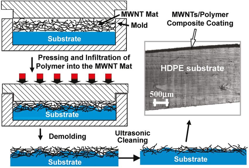
524 Viswanathan S. Saji
reduced the hydrophobicity, whereas the dodecyl functio- liquid immersion (in water, toluene, EtOH, and 1M HCl),
nalization screened the π–π interaction. The TMSS per- UV light exposure, and water jetting tests [107]. Wang
formed like glue, barred CNTs from aggregation, and low- et al. reported spray-coated SHPC coating with enhanced
ered the required CNTs for the SHPY [105]. A hot/cold wear resistance from an aqueous dispersion containing
water-repelling superamphiphobic (SAPC) surface was fab- CNTs and PTFE. Thin film fabricated on Si (CA of 154.1 ±
ricated by spray coating a suspension of MWCNTs, pre- 2° and SA < 2°) retained the SHPY even after 500 times of
pared via hydrolytic condensation of tetraethoxysilane abrasion test under 50 g/cm2 [134]. Belsanti et al. fabri-
(TEOS) and perfluorodecyltrichlorosilane (PFTS). The cated SHPC film via spraying CNT suspension on Al alloy
introduction of PFTS was beneficial for enhancing the coat- for anti-corrosion application [118]. A flexible, SHPC (CA
ing’s durability, whereas the TEOS addition was helpful to of 165 ± 2°) and transparent (>70%) PDMS/CNT strain
reduce the SE. Representative SEM images of the SAPC sensor was fabricated by spray coating CNT solution
coating displayed a random cross-linked network structure onto the PDMS nanowrinkle substrate [109].
with two-tier roughness composed of modified MWCNTs Li et al. presented an approach to creating an SHPC
(Figure 5b–d). At 1 mg/mL of CNTs, the fluorosilane surface from hierarchically combined polystyrene (PS)
wrapped most of the CNTs resulting in lower surface microspheres and CNTs. First, a monolayer of PS colloidal
roughness. As the concentration increased to 2 and crystals was spin coated on a glass substrate and dried at
4 mg/mL, the fraction of exposed CNTs increased with an 130°C; subsequently, Au layer was sputter coated, and
associated enhancement of micro/nanoscale roughness the sample was dipped into 0.1 M mercaptoethylamine
resulting in superior superamphiphobicity (SAPY) solution to facilitate linking of –COOH-terminated CNTs
(Figure 5e). The wettability varied considerably with on the PS spheres (CNT solution was drop coated on the
the CNT’s diameter (Figure 5f) [106]. modified colloidal layer). The surface was then immer-
The authors also reported a transparent, hot liquid- sion coated with EtOH solution of 20 mM PFTS and dried
repelling durable SAPC coating from a suspension of at 120°C. The CA before and after the PFTS modification
polysiloxane-modified MWCNTs in toluene, followed by was ∼33° and 165°, respectively. The CA decreased to 158°
calcination to form SiO2 nanotubes (SNTs) and subse- after 5 days of continuous immersion in water; however,
quent PFTS modification. The SNT/PFTS coating pre- no significant change was observed during long-term air
sented high chemical and mechanical durability during exposure studies [110]. Meng and Park employed as-
Figure 5: (a) Digital and (b–d) SEM images of the MWCNT-based composite SAPC coating. (e and f) CAs and SAs of n-decane on the spray-
coated surface as a function of (e) concentration and (f) diameter of MWCNTs [106]. Reproduced with permission from ref. [106]; © 2017
Elsevier Inc.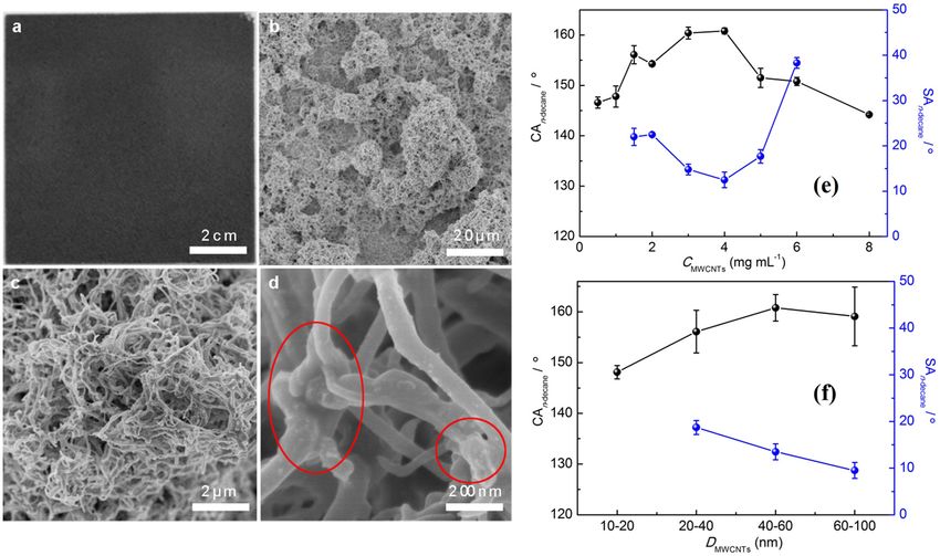
Superhydrophobic carbon nanostructures 525
purchased and functionalized MWCNTs (by refluxing in on CNT–PDMS systems. Zhang et al. reported an SHPC
H2O2), which was first dispersed in CHCl3 (0.5 mg/mL) coating via spraying CNT/PDMS/toluene suspension, fol-
and further mixed with a fluoropolymer (1 wt%), and lowed by curing at 120°C [133]. Caffrey and Gupta reported
dip coated on glass. A seven-time dip-coated film with a method of fabricating electrically conductive SHPC
10:3 (v/v) MWCNT/fluoropolymer displayed the highest coating with a micro-textured surface by adding CNT fil-
CA of 160.2°, along with 83.5% transmittance and 1.38 × lers to the PDMS matrix and duplicating the surface tex-
104 Ω/sq sheet resistance [121]. Dispersions of CNTs, GR, ture using a master. The surface displayed CA >160°,
and carbon black (CB) in water/organic solvents were without any additional modification. A MWCNT loading
investigated as water-repellent agents for hydrophilic of 4.4 wt% improved the conductivity by a factor >1011
wood by simple drop/dip coating [114]. over the pure PDMS [129]. Park et al. have developed a
Several works made use of laser in getting patterned/ conducting SHPC film with improved adhesion by using a
transparent SHPC surfaces. Kinoshita et al. achieved zirco-aluminate coupling agent. Here, CNTs were first
SHPC/SHPL micropatterning on CNT film using a laser- dispersed in CHCl3 and then in triton-x surfactant. Sub-
assisted process where the areas exposed to hyperthermal sequently, SiO2 NPs (10 vol%) were added, dispersed,
F-atom and O-atom beams, respectively, became SHPC sonicated, and then PDMS and curing agents were
and SHPL [111]. To obtain high transparent SHPC pat- added, sonicated, and the dispersion was used for spray
terned CNT clusters, femtosecond laser micro-machining coating. High CAs and low SAs were obtained until
was employed by Tang et al. [112]. 25 vol% of CNTs [135]. An SHPC flexible film with a
Li et al. hot-pressed raw MWCNTs (1,500°C, 3 min, sandwich-like structure consisting of PDMS, MWCNTs,
30 MPa, vacuum, spark plasma sintering) and the polished and a thermoplastic elastomer was fabricated by spray
sample was subsequently dipped into a commercial aqu- coating of the elastomer on the top side of the MWCNT
eous PTFE latex (1 s, ultrasonication) and heated at 310°C sheet and PDMS modification on the bottom side. The
for 20 min. The bulk composite (CNTs, tiny PTFE particles, top elastomer layer glued free MWCNTs together, the
and air) having nanometre-scale grains showed CA >160°. middle MWCNT layer formed a web-like conductive net-
The CA of the bare PTFE was ∼114° [113]. work, whereas the PDMS layer acted both as a glue and a
Rajiv et al. reported long-term-durable SHPC MWCNT– low SE component. Maximum CA (169.4°) and minimum
CNF composite coatings on fibre-reinforced polymer (FRP) SA (2.7°) were obtained when the PDMS concentration
sheets. The supercritical fluid processing method was used was 1.5 wt%. The loss of SHPY at a PDMS concentration
to reduce the composite flaws and the CNT’s aggregation. of >4 wt% was attributed to the thick coating formed
The composite layer displayed better SHPY (CA ∼ 171.6° and and the buried MWCNTs [137]. Jung et al. proposed a
SA ∼ 2.7°) than a corresponding coating made by physical highly reliable SHPC surface where CNTs were firmly
mixing (160° and 7.12°, respectively) [115]. immobilized on a PDMS/adhesive multilayer. The exposed
CNTs at the lower surface of the layer helped to enhance
the coating/substrate adhesion, whereas those exposed
2.1.3 As filler in organic coatings/composites with on the top surface contributed to SHPY. A CNT loading of
polymers 2.5 wt% was found to be essential for the SHPY. Tape
tests showed that the SHPC surface was robust against
Several works employed CNTs as fillers in the polymer adhesive material’s induced damages. The surface well
matrix to enhance mechanical durability. The incorporated preserved the SHPY even at 300°C (Figure 6a). Until
CNTs could also provide the required hierarchical surface 200°C, the SA remained < 2°, while at 300°C, it becomes
roughness for the SHPY. The CA and SA of the composite ∼3.7°. The CA of the bare PDMS sheet (116° at 20°C)
coating could be fine-tuned by regulating the aspect ratio or displayed an obvious decline with the rise of tempera-
concentration of the CNTs. Their inclusion could also pro- ture (∼100° at 300°C). Even at 10,000 kPa, the CA of
vide additional functionalities, such as conductivity, photo- the SHPC composite coating was reduced by ∼8° only
thermal effect, EMI shielding, and self-cleaning. (Figure 6b). The surface also presented excellent dur-
ability during bending, adhesion, water jet, and che-
mical tests [139]. Han et al. fabricated SHPC surface on
2.1.3.1 With F/Si polymers a flexible substrate via screen printing with a paste of
PDMS–PEG copolymer and MWCNTs. Superior SHPY
Other than the previous section’s works, there are many with >1,000 S/m of conductivity was attained at 25 wt%
reports on CNTs with F/Si polymers. Several works focused of PDMS–PEG [143].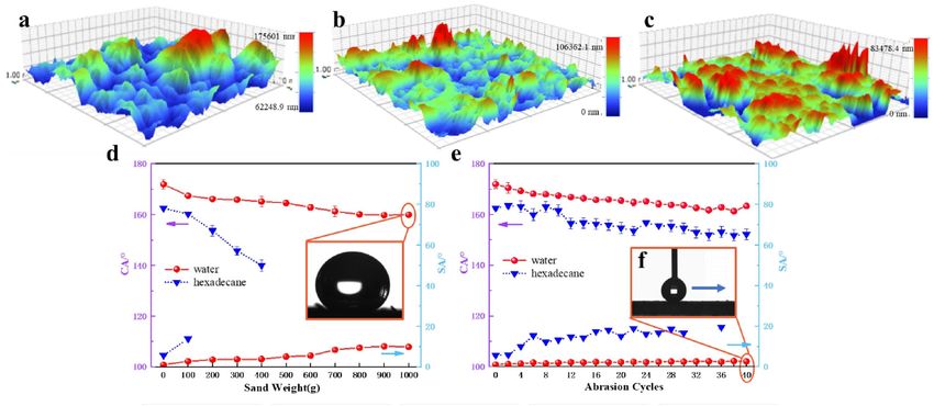
526 Viswanathan S. Saji
Figure 6: Stability test results of CNT-incorporated PDMS/adhesive (CIPA) layer with (a) heat and (b) pressure [139]. Reproduced with
permission from ref. [139] (https://pubs.acs.org/doi/10.1021/acsomega.7b01872); © 2018 American Chemical Society. For further per-
missions related to the material excerpted should be directed to the ACS.
Highly conductive nanocomposite coatings of fluo- shell-structured polyaniline (PANI)/CNT composite, SiO2
ropolymer dispersion with CB, CNTs, or GR nanofillers NPs, and 1H,1H,2H,2H-perfluorooctyltriethoxysilane (PFOS)
were studied. At 50 wt% of CNTs or CB, the SHPC surface were integrated synergistically into the ethylene tetrafluoro-
resisted water-drop impalement at 3.7 m/s. GR-based sur- ethylene (ETFE) matrix. Here, ETFE powder (1 g in 30 mL
face displayed the most inferior dynamic impact resis- ethyl acetate), SiO2 (0.05 g), and PFOS (0.2 g) were ultraso-
tance; however, the best conductive one [138]. Bayer et al. nicated with a selected amount of PANI/CNTs and the well-
fabricated electrically conducting SHPC polymer–CNT dispersed solution was used for the spray coating, followed
coating via an emulsion-based spray process. The emul- by curing at 300°C. A composite layer made from 6 wt% of
sion was composed of fluoro-acrylic latex solution (cap- PANI/CNTs revealed superior SAPC property, with CAs of
stone ST-100), toluene-MWCNTs, and MtOH. The spray- 159°, 163°, and 167° for ethylene glycol, glycerol, and water,
coated film was cured at a temperature above the melting respectively (with SAs < 5°). However, at concentrations
point of the fluoro-acrylic latex (>160°C) to yield the >6 wt%, surface cracks were evident. The optimum coating
SHPY (CA >165°, SA < 5°). However, increasing the CNT demonstrated durable SHPY with droplets of a wider
loading beyond 17 wt% caused coating flaking and poor pH range (1–14) and thermal stability at temperatures
substrate adhesion [132]. Zhang et al. described highly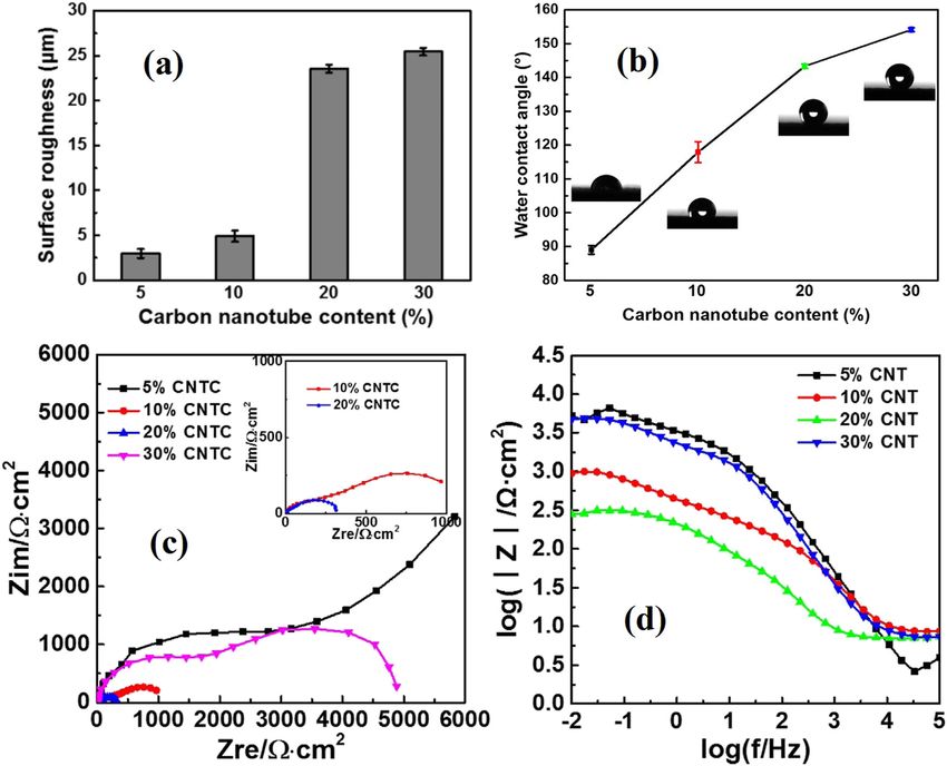
Superhydrophobic carbon nanostructures 527
Figure 7: Variation of CAs and SAs of resin-coated samples with (a) concentration of CNTs, (b) abrasion cycles, (c) water pressure, and
(d) duration of water-jet test under 200 kPa [140]. Reproduced with permission from ref. [140]; © 2015 The Royal Society of Chemistry.
reinforced fillers (CNTs or GR) provided the required hier- After a low SE fluorosilane modification (by CVD), the
archical surface structure; a silane-coupling agent was CNT/PVDF–HFP membrane displayed SHPC and super-
also employed. The sprayed and heat-treated (320°C) oleophilic (SOPL) properties [145]. SHPC and SOPL porous
coating exhibited a CA of ∼161° and an SA of 2°. The CNTs/PVDF composite was prepared via gel formation
wettability varied both as a function of SiR and CNT con- and freeze drying. The study proved that even a small
tent, and the optimized coating was composed of 10 wt% amount of CNTs could considerably enhance the porosity
of SiR and 1 wt% of CNTs. The evenly distributed CNTs and surface roughness of PVDF [146]. Kousalya et al.
with self-lubricating properties were helpful to reduce the made a mixed wetting surface with interchanging par-
abrasion loss significantly. After 2,500 times of friction allel SHPC/SHPL bands through graphitic petal-deco-
(1,000 sandpaper, 500 g, 37.5 circles/min), the sample rated CNT coatings via PTFE deposition, shadow mask,
continued to be SHPC with a CA of 150 ± 2°. After 5,000 and oxygen plasma treatment [147].
cycles, the CA becomes ∼139°. Compared with the PPS Wettability transitions in a spray-coated coating of
coating (0.2106 g), the SHPC coating’s weight loss (0.063 g) polyfluo 150 wax and fluorocarbon-modified MWCNTs
considerably decreased [142]. (1:4 wt ratio, acetone–ethyl acetate solvent) were studied
Song et al. reported nano-hybrid membrane based on as a function of temperature. SHPY was attained at 150,
chitosan (as the matrix), cationic chitosan (chitosan- 200, and 360°C, whereas SHLY resulted at 300°C. The
modified by a triazine derivative), MWCNTs, and a silicon variation was associated with the melting/decomposition
coupling agent, which was further modified by low SE of the wax and the related phase separation [122]. Run-
perfluorooctanesulphonyl fluoride. The membrane with graeng et al. revealed a slippery liquid infused porous
3 wt% MWCNTs showed excellent SHPY [144]. Wang surface consisting of SHPC MWCNT–PTFE layer filled
et al. fabricated nanofibre composite membrane of CNTs with a low surface tension liquid. Water, honey, ketchup,
and PVDF-co-hexafluoropropylene (PVDF-HFP) using oil, and bacterial biofilms freely slipped off the surface
electrospinning and pressure-driven filtration processes. without leaving any apparent wreckage [148].528 Viswanathan S. Saji
Peng et al., in earlier work, reported a way for trans- resistance of a spray-coated CNT–EP composite were
forming common polymers into SHPC conductive surface attributed to the even dissemination and strong bonding
by simple pressing of a layer of MWCNTs on a polymer of CNTs on the EP resin. The suspension for the spray
melt (Figure 8). Under appropriate conditions, the CNTs coating was prepared by adding EP resin (200 mg) to a
were partly inserted inside and partly exposed outside dispersion of CNTs (200 mg) in acetone (100 mL). A sub-
the coatings’ surface, creating a carpet-like structure, sequent curing step at 120°C facilitated melting and ingres-
providing both SHPY and conductivity [126]. sion of EP resin to CNT/substrate interface and ensured
coating with exposed CNTs (CA ∼ 166° and CAH ∼ 4°)
[151]. Hsu et al. reported amphiphilic polyamine-modified
2.1.3.2 With polyurethane/epoxy/PS CNT/EP SHPC film by using a dispersion of as-purchased
CNTs (0.05 g), polyisobutylene-amine copolymer (PB-
Several studies explored CNTs as filler/hydrophobicity amine, 0.1 g), THF, and EP resin (0.071 mmol, 0.025 g).
promoter with polyurethane (PU), epoxy (EP), and PS The SHPY (CA > 152° and CAH ∼ 7°) of the drop coated
resins. Hejazi et al. described a single-step pressing and cured (80–150°C) surface was primarily attributed to
method to fabricate SHPC, self-cleaning, and mechani- the well-ordered orientation of CNTs. The CA augmented
cally durable PU/CNT composite. After placing the PU to ∼158° at an optimized PB-amine/CNT wt ratio of 1/2;
sheet into a pre-designed mould, 15 mg of CNT powder however, it declined with a further increase of PB-amine
(∼2 vol%) was distributed, and the surface was pressed content (Figure 9a). The corresponding variation of sheet
under 4 MPa for 10 min and heated to 180°C. The pressing resistance is also shown (Figure 9a). Their time-depen-
time had a significant effect on the type of SHPC surface. dent CA variation studies displayed excellent durability
A longer processing time (60 min) resulted in sticky SHPY for PB-amine/CNT and PB-amine/CNT/EP coatings. On
[149]. A report on spray-coated SAPC coating used fluori- the other hand, the pristine CNT film failed within 1 h
nated MWCNTs as a nanoroughness promoter and fluori- (Figure 9b) [152]. A robust SAPC EP/PVDF/FEP spray
nated PU as a low SE binder and acetone/toluene cosol- coating with incorporated CNTs and SiO2 (2.5 wt% each)
vents [150]. Reports on PU-CNT-based aerogels/sponges was reported. The synergistic combination of SiO2 and
are described in Section 2.1.5. CNTs was utilized to create the required multilayer struc-
Besides SHPY, the CNT fillers in the EP matrix could ture. Fluorinated ethylene propylene (FEP, 17.8–18.8 mJ/
help to overcome their inherent brittleness and poor wear m2) was employed to reduce the SE [153]. The authors
resistance. The high mechanical strength and abrasion also reported an SAPC and electroactive bilayer
Figure 8: Scheme showing fabrication of SHPC and conductive MWCNTs/polymer composite coating. An optical image of the coated sample
is also shown [126]. Reproduced with permission from ref. [126]; © 2010 American Chemical Society.Superhydrophobic carbon nanostructures 529
Figure 9: (a) Variation of sheet resistance and CA as a function of PB-amine/CNT weight ratio. (b) Time-dependent CA variation in water
[152]. Reproduced with permission from ref. [152]; © 2013 American Chemical Society.
composite coating by integrating EP, PANI, FEP, SiO2, (10 wt%) or a higher (40 wt%) loading does not yield
and CNTs by air and electrostatic spray methods. The SHPY and that was, respectively, attributed to the insuf-
brilliant cross-linking effect of EP resin and the nanofil- ficient CNT content and the wider spacing between the
lers’ reinforcement enhanced the mechanical properties neighbouring agglomerates [155]. An SAPC coating was
considerably and provided a durable SHPC surface with fabricated by spraying a suspension of fluorinated
excellent adhesion and wear resistance [154]. MWCNTs (hydroxylated MWCNTs dispersed in dry THF
Zhang et al. have studied spray-coated SHPC MWCNT/ with added 1H,1H,2H,2H-perfluorodecyltriethoxysilane
EP nanocomposite coating on carbon steel (CS), where the [PFDTS]) and EP adhesive. The F content was as high
agglomerated CNTs mainly constituted the hierarchical as 47.4%. The natural crowding of the CNTs and the sol-
microstructure. Different amounts of CNTs (0.125, 0.25, vent evaporation created the required surface roughness
0.5, and 0.75 g) were first dispersed in the EP resin and the microstructure. The surface maintained the SAPY
(1.875 g in 40 mL of acetone), to which jeffamine D230 even after 40 abrasion cycles. Excellent durability was
(0.625 g) was added and stirred to prepare the dispersion. observed during finger wiping, sand dropping, and sand-
The coated/cured (at 60°C, 2 days) sample with 30 wt% paper abrasion tests (Figure 10) [156]. Li et al. employed
CNT loading displayed slippery SHPY. However, a lower nanoscale (MWCNTs) and microscale (graphite and
Figure 10: Surface 3D map images after different abrasion cycles: (a) 0, (b) 20, and (c) 40. CA and SA variation with (d) sand impinging
weight and (e) abrasion cycles [156]. Reproduced with permission from ref. [156]; © 2020 Elsevier.530 Viswanathan S. Saji
expanded graphite) fillers, uniformly dispersed in EP and poly(furfuryl alcohol), respectively. Men et al. used
resin. First, E51 EP resin (2 g) and THF (3 g) were stirred poly(furfuryl alcohol) as adhesion and low SE agents,
and added to a solution comprising MWCNTs (0.16 g), gra- along with fluorocarbon-modified MWCNTs and PTFE.
phite powder (0.5 g), EG (0.04 g), PFOS (0.1 g), and THF The spray-coated and cured (70–180°C) coating dis-
(5 g); subsequently, 0.2 g of diethylenediamine was also played superior SHPY when the three components’
added. The SHPY was not destroyed during the abrasion mass ratios were 1:1:1 [167]. Han et al. employed CNTs
testing (200 sandpaper, 500 g, 20 cm, 50 cycles), even if and reduced-GO (RGO) sheets to nucleate PC crystalliza-
several powders have been worn out and the coating tion through phase separation. A 10 s of dipping of the
thickness reduced [157]. polymer sheet in the MWCNT solution was enough to
Several studies explored PS/CNT coatings [158–164]. shape the SHPC surface with a CAH ofSuperhydrophobic carbon nanostructures 531
2.1.4 CNT/metal/ceramic hybrids images displayed two different wire-like nanostructures:
curl and straight NWs. The composite surface showed CA
In addition to a few works discussed above, several of 157 ± 2°, compared to 120 ± 2° of pure CNTs, and 86 ± 2°
reports are available on SHPC hybrids of different ceramic of pure Si wafer. The film retained a CA of 141° even after
oxides and metals with CNTs (with or without polymers) continuous water immersion for 2 weeks [184]. Jiang et al.
[176–195]. Wang et al. combined MWCNTs, Ni NPs, and prepared SHPC coating (CA of 161° and SA < 2°) by
diamond-like carbon (DLC) film to fabricate a robust spraying a suspension of SiC particles and CNTs on
SHPC MWCNT-Ni/amorphous-carbon coating by one-step EVA plastic [185].
ED. The as-prepared film displayed a CA of 158.89° and an Liu et al. fabricated a durable SHPC Al2O3/CNT/PDA/
SA of 1.99°. The integration of CNTs and Ni NPs increased PTFE coating. The synergistic effect of the Al2O3 hydra-
the surface roughness and enhanced the abrasion resis- tion and the addition of CNTs/PTFE promoted mecha-
tance. Even after 20 abrasion cycles (sandpaper, 100 g, nical and chemical durability (see Section 3.1.1) [186].
10 cm), the CA maintained at ∼152° [176]. The authors Highly active SHPC Co3O4/CNT catalyst was synthesized
also reported a corresponding MWCNT/Co film by ED [177]. by in situ growth of Co3O4 NPs on MWCNTs in the pre-
Several works employed SiO2. Hsieh et al. decorated sence of a polymer surfactant, followed by PFDTS modi-
polyacrylonitrile-based carbon fibre (CF) fabric with sol– fication [187]. Shen et al. fabricated antibacterial SHPC
gel-made SiO2 microparticles and CNTs. A wet chemical Ni/WO3/CNT metal matrix coating by ED and PFDTS modi-
impregnation approach was used to disperse SiO2 onto fication, followed by curing at 120°C. The optimized ED
the fabric, and then CVD (900°C) was employed to grow parameters for the SHPY (CA ∼ 168.5°, SA ∼ 3°) were a
CNTs. A CA > 170° was observed in the CF/SiO2/CNT three- bath having 0.5 g/L CNTs and a deposition current density
tier structure [178]. Peng et al. fabricated SHPC conductive of 4 A/dm2. The coating remained SHPC when abraded for
coating by air spraying using a mixture of functionalized 180 cm (600 sandpaper); however, after 200 cm of abra-
MWCNTs and aqueous SiO2 sol, followed by fluorosilane sion, the CA changed to 148.9°. SHPY was maintained
modification. The study explored two types of CNTs: even after 50 cycles of the tape-peeling test; nevertheless,
hydroxylated (h-MWCNTs) and copolymer/silane-wrapped the CA reduced to 145.1° after 55 cycles [188].
(w-MWCNTs). The threshold concentration for achieving A transparent SAPC coating was fabricated using a
the SHPY varied with the type of the CNTs, i.e., 2.7 vol% template approach where CNTs were sol–gel-coated with
for w-MWCNTs and 4.8 vol% for h-MWCNTs. The nano- SiO2 and the CNTs–SiO2 suspension was spray coated
composite coatings retained SHPY for more than 1 year in onto glass slides and cured at 600°C and further sub-
outdoor weathering. The study also showed that the jected to a fluorination step. The coated surface displayed
w-MWCNTs/SiO2 coatings’ durability increased with coating many protrusions composed of SiO2 NPs and SNTs. The
drying temperature. During continuous water immersion transparent coating sustained SAPY even at 400°C [189].
studies, the coatings dried at 160°C and 240°C retained Li et al. fabricated semitransparent SOPC SNT coatings on
SHPY for 20 and 27 days, respectively. However, for a glass with a post-PFTS modification. The SNT layer was
coating without high-temperature curing, the SHPY was spray coated using a dispersion of PDMS-modified
lost within 3 days [179]. Li et al. reported spray-coated MWCNTs and subsequently calcined to remove the CNT
SAPC CNT–SiO2 hybrid coating. Here, h-MWCNTs were first template. The SNT layer’s microstructure and hence the
ultrasonically dispersed in EtOH and then 5 mL of 25 wt% SAPY could be controlled by optimizing the diameter and
aq. NH3 and TEOS-EtOH solution were added. The well- concentration of MWCNTs. The surface displayed excel-
dispersed solution was used for spraying, and the coated lent superwettability for water, n-decane, n-hexadecane,
glass was vacuum dried and subjected to CVD of PFOTS toluene, and several hot liquids [190].
[180]. Wang et al. demonstrated SHPC spray-coated h- Zhu et al. fabricated an SHPC film by spray coating a
CNT–SiO2 NP composite coating with a post-fluorination dispersion of ZnO NPs and MWCNTs in PDMS solution
step [181]. SHPC SS mesh was fabricated via coating of [191]. Barthwal et al. reported ZnO/MWCNT coating (by
oxidized MWCNT inks with post-modification in perfluoro- sol–gel and dip coating) for Cu mesh, with a subsequent
silane/SiO2 NP solution and curing at 150°C [183]. PDMS modification. The SHPY was maintained during
Yu et al. presented a method to fabricate SHPC nano- direct immersion in 3.5 wt% NaCl for 15 h and ambient
composite film consisting of CNTs and SiC NWs. The Si air exposure for 2 months. A composite coating with
substrate was coated by Ni and amorphous-carbon films 2.5 wt% MWCNTs presented a CA of 156° and an SA of
by high vacuum magnetron sputtering, and subsequently 4°. The CAs recorded for coatings with 1 and 5 wt%
heated with Al powder at 1,000°C in a tube furnace. SEM MWCNTs were 151° and 145°, respectively [192].532 Viswanathan S. Saji
SWCNT/GR composite was fabricated via covalent SOPL sponge by cross-linking epichlorohydrin with ethyl
crosslinking through two different coupling strategies: cellulose (CL) sponge and further complexing with sila-
carbodiimide and Sonogashira. The results showed that nized CNTs and modifying with SiO2/HDTMS. The SHPC/
the composite assemblies obtained by Sonogashira cou- SOPL material (water CA ∼ 158.2°, oil CA ∼ 0°) displayed
pling exhibited higher surface areas and greater CAs superb mechanical strength (withstand 28.6 kPa pres-
(159–163°) when compared to the carbodiimide coupling sure) due to the facilitated chemical cross-linking and
[193]. the incorporated nanofillers. The sponge also revealed
excellent thermal (up to 330°C) and chemical durability
(acid/alkali/salt solutions) [197].
2.1.5 Sponges, foams, aerogels, fabrics, and meshes Several works explored SHPC CNT coating on cotton
fabrics. Makowski et al. fabricated SHPC cotton woven
Several works investigated CNT-based sponge/foam/ fabrics covered with silane-modified MWCNT layer [210].
aerogel/fabric/mesh for different applications including Zheng et al. manufactured a conductive SHPC cotton
oil separation and sensors. Polymer/CNT composite sponges fabric (CA of 162°) by LbL assembling carboxylated and
are mainly studied [196–232]. aminated MWCNTs and further modifying with PDMS.
A few works reported SHPC CNT-only sponges/bun- The assembly was repeated for different cycles and sub-
dles [198–200], whereas a few others studied CNTs + GR sequently dipped in 5 wt% hexane solution of PDMS and
sponges/monoliths [201–203]. CNT/polymer composite vacuum dried at 135°C [211]. SHPC, flame-retardant, and
sponges are attractive for practical applications due to conductive cotton fabric was fabricated by LbL assembly
their improved mechanical durability. Several works of poly(ethylenimine), ammonium polyphosphate, and
employed composite structures of CNTs with commercial CNTs, followed by PDMS treatment [212].
PU foams. Ge et al. presented a dip-coating method for A few studies explored CNT coating on SS mesh.
building SHPC and SOPL CNT/SiO2-coated PU sponge Lee et al. described a technique to directly synthesize
where the as-purchased PU sponge was consecutively VACNTs on commercial SS mesh by CVD for oil separa-
dipped in EtOH suspensions of PVDF-HFP and CNTs/ tion [91]. Lu et al. used a spray-coating method for
SiO2, and cured at 140°C, blew off the loose particles CNT layer deposition onto steel wire mesh. Poly(methyl-
and subjected for further fluorination in EtOH solution methacrylate) (PMMA) was used to deliver robust bonding
of perfluorotetradecanoic acid, and dried at 80°C [204]. between CNTs and the mesh surface [213].
Sultanov et al. also employed a dip-coating method Several studies on SHPL and underwater SOPC compo-
where commercial PU sponges’ walls were coated with site membranes for oil separation applications are avail-
RGO and MWCNTs [205]. PU/MWCNT composite with able that include SWCNT/PDA/PEI [216], CNT/FeOOH NR
a nano/microscale hierarchical porous structure with [217], SWCNT/TiO2 [219], CNT/PS/Au NP [220], Ag/PAA/
copious air holes was fabricated via non-solvent-assisted CNT [221], MWCNT/MnO2 NW [222], polyzwitterion/TiO2/
thermal phase separation. Morphology analysis revealed CNT [223], magnetic CNT–PVA [224], and CNT/PAA brush
uniform dispersion of the carboxylated-CNTs in the porous [225] membranes. Quite a few works reported CNT-based
structure, facilitated by strong hydrogen bonding interac- desalination/water treatment membranes including ACNT
tion. The composite monolith displayed excellent mechan- membrane [226], MWCNT/PVDF/PDMS [227], CNT/PFDTS
ical elasticity and chemical durability [206]. Hong et al. [228], CNT/polyvinylidene fluoride-co-hexafluoropropy-
reported a flexible, conductive SHPC PU/CNT/silane aerogel lene [229], bauxite/NiO-CNT [230], CNT/PVDF/PP [231],
composite microfibre. CNTs (2.5 wt%) were mixed with PU and SS-CNT [232] membranes.
first and then with PFTS, and further, SiO2 aerogel particles
were embedded in the matrix [207].
A few studies employed melamine (ML) sponges [205,
208,209]. Mechanically robust 3D SHPC composite sponges 2.2 Carbon nanofibres
were prepared using ML as a scaffold, MWCNTs, GR, or
activated carbon as SHPC and robust coating material, 2.2.1 CNFs only
and a polyphenol–Fe3+ complex as a low-cost adhesive.
The optimized loading of MWCNTs for the SHPY was 3% This section discusses CNF-based SHPC surfaces [233–270].
[208]. A few works on microscale CFs are also included.
Cellulose-based materials are attractive in terms of Several earlier (before 2010) reports addressed SHPC
abundance and eco-friendliness. Lu et al. made SHPC/ vertically aligned CNFs [233–235,244]. Hsieh et al.Superhydrophobic carbon nanostructures 533
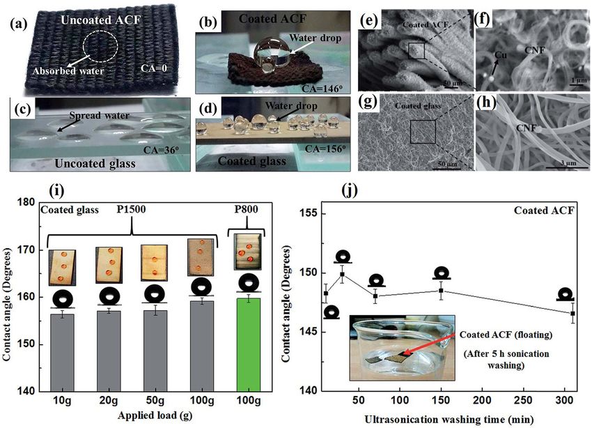
demonstrated the influence of the F/C ratio on the SHPY Siddiqui et al. employed a two-step plasma-sputter/
of CNFs prepared by a template-assisted method and CVD (300°C) process to fabricate SHPC CNFs on activated
showed that the CA increases with the increase of F/C CF (CA ∼ 146°) and glass (CA ∼ 156°) substrates without
ratio [234]. Wang et al. employed an alumina template the use of fluorosilanes. The CAs of the corresponding bare
to fabricate aligned SHPC CNFs (CA of 153.1 ± 2.2°) via CF and glass surfaces were ∼0° and 36° (Figure 11a–d).
dipping in hydrophilic PVA polymer followed by a car- SEM images displaying the surface morphology of the
bonization process (at 600°C) and subsequent partial SHPC surfaces are also shown (Figure 11e–h). The SHPY
template removal. No low SE modification was used. was well-maintained during the abrasion test with dif-
The CA of the corresponding disordered CNFs was ferent sandpapers and applied loads. An already abraded
only 126.3 ± 3.7° [235]. Hima et al. studied three dif- surface (using P1500 for nine cycles) retained excellent
ferent types of CNSs (caterpillar-like fibres, tubes, and durability even after subjecting a second round of abra-
interwoven spheres) by CVD (700°C, morphology varied sion studies (P800, 100 g) (Figure 11i). The surface pre-
with the growth duration) and showed that the cater- sented outstanding chemical durability over a wider pH
pillar-like CFs and interwoven carbon spheres exhibited and hot water (95°C). The SHPY was well-maintained
high CAs of 163 ± 2° and 168 ± 2°, respectively, and that during an ultrasonication test for 300 min (Figure 11j)
was attributed to their unique surface structures. The cor- [248]. Xu et al. employed an SHPC CF sponge without
responding tube structure displayed CA ∼ 140° only [244]. any chemical modification for oil separation [247].
Tsai et al. provided a detailed account of drop-impact
dynamics on SHPC surfaces made up of CNF forest and
microscale-patterned polymers. The study showed that 2.2.2 With polymers
the multiscale nanoroughness had only a negligible effect
on the impact dynamics when Wn was ≤120; however, it Several works explored CNFs with silanes/fluorosilanes
was significant at Wn ≥ 120 [236]. Ogihara et al. demon- [250–258]. In 2011, Das et al. reported a spray-coated
strated EPD-made SHPC coloured films using different SHPC self-cleaning CNF/PTFE/composite-polymer coating.
hydrophobic pigment particles, including vapour-grown CNFs were employed mainly to adjust the conductivity
CNFs and CB [237]. without compromising the SHPY, whereas PTFE particles
An SHPC CF coating with boosted corrosion protec- were used as hydrophobic fillers. A solution blend of PVDF
tion capability was developed on Zn via CVD at 350°C. and acrylic PMMA was used as the composite–polymer
The CAs measured on Zn-CF and bare Zn surfaces were matrix. The optimized CNF loading amount was 1.1 wt%
153.3 ± 1° and 68.2 ± 1°, respectively [238]. Durable CNF [250,252]. The authors also reported a water-based spray
coatings were developed on mild steel (MS) and AZ31 Mg coating of commercial fluoroacrylic copolymer and hollow
alloy by subsequent plasma sputtering and CVD. The CA CNFs. The study showed that replacing lengthy CNFs with
of the bare MS (∼69°) increased to ∼150° (SA ∼ 7°) after short solid nanowhiskers would help produce more stable
the CNF coating. The corresponding transition for the Mg fluoropolymer–nanocarbon dispersion. At a CNF concen-
alloy was ∼66.7° to ∼145° [239]. tration of >30 wt%, self-cleaning SHPY was observed,
Several works employed SHPC fabrics made of CFs whereas oil-droplet mobility was experienced at 60 wt%
[241–245]. Meng et al. explored the role of CNFs in pre- loadings only [251].
paring SHPC and electroconductive surface on glass fab- CNF–PDMS systems were explored. Seo et al. pre-
rics. Homogeneous CNFs were grown by CVD, and the pared CNFs by CVD and surface modified by PDMS (CA
surface modified with a fluoropolymer [243]. Ko et al. ∼ 170°). A corresponding STA-modified film showed a CA
utilized preferential oxygen plasma etching to fabricate of ∼150° only [253]. Abdulhussein et al. employed one-
high-aspect-ratio CF-network-structures with morphology step vacuum filtering to fabricate SHPC (CA > 163° and SA
ranging from nanopillar to hairy. A subsequent siloxane < 5°) and SOPL (oil CA ∼ 0°) CNF/PDMS composite block
modification increased CA from 147° (pristine CFs) to 163° with high mechanical and chemical stability [254]. A
(30 s of siloxane vapour treatment) with a reduction of robust SHPC (CA ∼ 163°) and SOPL CNF/PDMS-modified
CAH from 71° toYou can also read