An Enhanced Traffic Split Routing Heuristic for Layer 2 and Layer 1 Services
←
→
Page content transcription
If your browser does not render page correctly, please read the page content below
(IJACSA) International Journal of Advanced Computer Science and Applications,
                                                                                                           Vol. 13, No. 1, 2022

      An Enhanced Traffic Split Routing Heuristic for
             Layer 2 and Layer 1 Services

                                  Ahlem Harchay, Abdelwahed Berguiga, Ayman Massaoudi
                                                   Department of Computer Science
                                                      Jouf University, Sakakah
                                                           Saudi Arabia

    Abstract—Virtual Private Networks (VPNs) have now taken            the company’s information system. The question that may arise
an important place in computer and communication networks.             then is how to ensure access within a structure sometimes
A virtual private network is the extension of a private network        spread over large geographical distances? In concrete terms,
that encompasses links through shared or public networks, such         how can a branch of a company access data located on a server
as the Internet. A VPN is a transmission network service for           in the headquarters several thousand kilometers away?
businesses with two or more remote locations. It offers a range
of access speeds and options depending on the needs of each site.          Virtual private networks (VPNs) have been set up to
This service supports voice, data and video and is fully managed       respond to this type of problem and takes an important place in
by the service provider, including routing equipment installed at      computer and communication networks. As pointed out by [4],
the customer’s premises. According to its characteristics, VPN         a VPN is the extension of a private network that encompasses
has widely deployed on ”COVID-19” offering extensive services
                                                                       links through shared or public networks, such as the Internet.
to connect roaming employees to their corporate networks and
have access to all the company information and applications.               It offers a range of access speeds and options depending
Hence, VPN focuses on two important issues such as security            on the needs of each site. This service supports voice, data and
and Quality-of-Service. This latter has a direct relationship with     video and is fully managed by the service provider, including
network performance such as delay, bandwidth, throughput, and          routing equipment installed at the customer’s premises [5].
jitter. Traditionally, Internet Service Providers (ISPs) accommo-
date static point-to-point resource demand, named, Layer 1 VPN
                                                                       Indeed, the damaged caused by ”COVID-19” on global econ-
(L1VPN). The primary disadvantage of L1VPN is that the data            omy leads company networks on looking for VPN solutions
plane connectivity does not guarantee control plane connectivity.      to establish a private communication to the corporate intranet
Layer 2 VPN is designed to provide end-to-end layer 2 connection       while traveling from home.
by transporting layer 2 frames between distributed sites. An
L2VPN is suitable for supporting heterogeneous higher-level
                                                                           Both service providers and customers are starting to realize
protocols. In this paper we propose an enhanced routing protocol       the benefits of VPN solutions. New applications such as
based on Traffic Split Routing (TSR) and Shortest Path Routing         voice, telemedicine and video on demand make it possible to
(SPR) algorithms. Simulation results show that our proposed            envisage an increase in productivity and a reduction in costs.
scheme outperforms the Shortest Path Routing (SPR) in term             However, VPNs are not only interested in extending LANs
of network resources. Indeed, 72% of network links are used by         at a lower cost, but also in the use of specific services or
the Enhanced Traffic Split Routing compared to Shortest Path           functions ensuring quality of service (QoS) and security of
Routing (SPR) which only used 44% of the network links.                exchanges [6] [7]. Indeed, the notion of quality of service
   Keywords—Virtual private network; enhanced traffic split rout-      makes it possible to formalize the requirements for each type
ing; quality of service; shortest path routing; layer 1 VPN; layer 2   of service in terms of performance criteria: bandwidth, end-to-
VPN                                                                    end transmission delay, packet loss rate, jitter, etc. Each service
                                                                       may have different quality requirements.
                      I.   I NTRODUCTION                                   Services such as voice or video impose very strong con-
                                                                       straints on the quality of transmission: transmission delays or
    Computing, and networks in particular, have changed a              data loss must not degrade communication or the broadcasting
lot over the past twenty years. The flow of information and            of a video stream. In order to support real-time and multimedia
the emergence of new technologies have increased consider-             applications on virtual private networks, it is necessary to
ably [1]. It is now possible to exchange substantial data of all       develop routing algorithms which take QoS parameters into
types as well as to transmit voice and video over computer             account. Routing algorithms with QoS must be adaptive and
networks [2].                                                          flexible for efficient management of resources in the network
                                                                       [8]. In practice, routing with QoS has not worked well.
   Indeed, with a modern economy based on new information
and communication technologies, most companies use a set                   The objective of routing is to determine a route (i.e. a
of means for the implementation of a reliable and flexible             set of links to be traversed), respecting certain constraints, to
computer network [3]. This network allows corporate users to           establish a connection from a source node to a destination
share resources such as printers, files and data. As a result, the     node. The purpose of a routing algorithm is to allow the
need for remote connection to corporate resources has become           calculation of the route between those two nodes within the
common. Remote applications thus become the main tool of               meaning of a certain criterion?
                                                          www.ijacsa.thesai.org                                           775 | P a g e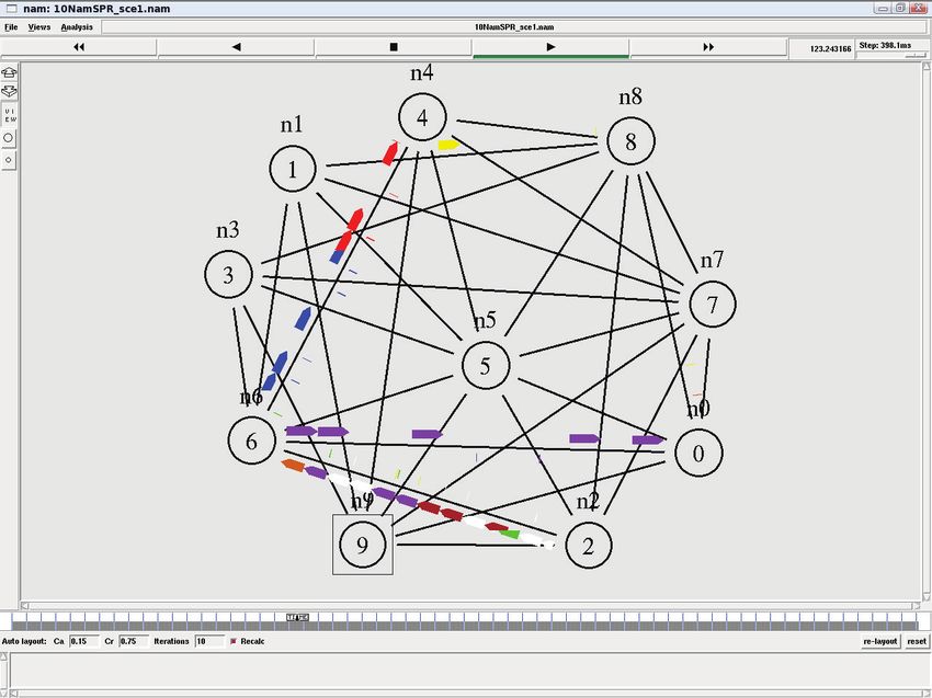
(IJACSA) International Journal of Advanced Computer Science and Applications,
                                                                                                         Vol. 13, No. 1, 2022

   The remainder of the paper is organized as follows. The          work, a random generator graph named ”Brite” is used [19].
next section will focused on different algorithms such as Wax-      The BRITE topology generator assigns each link with a delay
man and Brite algorithms. Section 3 highlights the approach         based on its physical distance. The algorithm can be described
proposed in this work. Then, an analysis of the performance of      as follows [20]:
our prototype system implemented using simulation model will
be described in Section 4. In Section 5, numerical results are          •    Firstly, we specify the number of nodes on the net-
presented to show the effectiveness of the proposed algorithm.               works.
Lastly, the conclusion and future work are outlined in Section          •    For a link creation between two nodes u and v we
6.                                                                           define the probability P (u, v) :
                                                                                                                −d(u,v)
                  II.   L ITERATURE R EVIEW                                                  P (u, v) = β exp     Lα                 (1)
    VPNs allow remote users, partners and providers to access       Where,
certain parts of their networks (intranets). They also allow
the deployment of many types of applications such as real-              •    d(u, v): the distance separating from node u to node
time voice or video, critical business management software or                v;
interactive applications [9] [10]. Originally, companies using
VPN solutions used ”layer 1” services such as ”leased lines”            •    L: the maximum distance between node u and node
(and referred to as layer 1 VPN, L1VPN). Leased lines are                    v;
dedicated connections that a telecom operator operates directly         •    α and β: These two constant parameters are defined
between two customer sites, providing a permanent connection                 in the interval (0.1].
at a determined speed. Although leased lines offer users the
confidentiality and reliability of transferred data, they suffer        When the constant α is decreased, we noticed that the
from a lack of flexibility compared to other types of layer 2       link’s density on the network is increased. Based on the
solutions such as Frame Relay, ATM, L2TP, L2F or also more          link probability (u, v) a link is added or not between u and
recently Carrier/Metro Ethernet.                                    v. In a shortest path tree problem, we consider a directed
                                                                    graph G = (V, E), where V represents the set of nodes
    However, as mentioned in [11] [12], this type of VPN            and E the set of links. Each edge has a weight Pi . A path
is characterized by its prolificity in singular domain and the      C =< e1 , e2 , ..., en , > has a weight which represents the sum
lack the Quality of Service (QoS) during the inter-domain           of the weights of the edges constituting the path. The shortest
routing which lead to inhibit its scalability and flexibility.      path from a vertex d to a vertex a is the minimum weight path
Another issue with L1VPN is the inter-configuration of a            that connects d to a [21].
customer on another Service provider network as the policies
are distinctives. This can be solved using the address mapping          The two algorithms Bellman-Ford and Dijkstra described
mechanism, unfortunately , this latter is not well-defined in       in [22] are two well known shortest path algorithms.
standard specifications [13].                                       Shacham [23] proposed a maximum bandwidth tree algorithm
                                                                    to distribute data hierarchically. It uses an algorithm close to
    In fact, ”layer 2” VPN services (or also layer 2 VPN,           Dijkstra to calculate the maximum bandwidth of a single path
L2VPN) have allowed service providers to offer their cus-           to all destinations.
tomers a connection similar to that offered by leased lines. On
the other hand, with L2VPN it is no longer necessary to have            The principle of this algorithm is as follows:
a dedicated leased line for each network interconnection. The
clients share a single physical line and each has its own logical       1)      Determine the maximum bandwidth paths available
channels to send its traffic [14]. Layer 2 VPN services are                     between the different nodes.
attractive to the service operator because they do not require          2)      Sort the receivers according to their reception capac-
the operator to participate in the design and configuration of                  ities.
layers 2/3 of the customers’ LAN. Also, the management and              3)      Add recipients to the maximum bandwidth tree one
maintenance of the control plan are carried out by the customer                 by one.
and they are transparent to the operator’s network [15] [16].
                                                                    This hierarchical distribution approach gives for each individ-
    The major problem with L2VPN is security. Unlike L1VPN          ual receiver the rate at which it will receive data from the
where each customer has their own private line, a layer 2           source. The bandwidth will then be allocated appropriately.
VPN is deployed on a shared network infrastructure that can
be managed by national and international network service                              III.     P ROPOSED A LGORITHM
providers. As a result, several companies disagree that their
data should be transferred through shared, unsecured tun-               As aforementioned, there are many issues on deploying
nels [17]. One solution would be to offer a layer 3 or L3VPN        Dijkstra and Bellman-Ford for routing protocols using two or
VPN service. Security is usually provided by a combination          more constraints. Dijkstra as well Bellman-ford are deployed
of tunneling and encryption methods. The best known is              where we using one constraint and offer good paths. However,
the one that implements the IPSec (IP Security) protocol.           when we need the formation of a balanced system when
IPSec is a ”layer 3” security protocol. It is based on the IP       distributing the load this is not guarantee by Dijkstra and
protocol and offers tunneling and security features, including      Bellman-ford which use an order of priority in the constraint’s
encryption, authentication and key management [18]. In this         choice.
                                                        www.ijacsa.thesai.org                                             776 | P a g e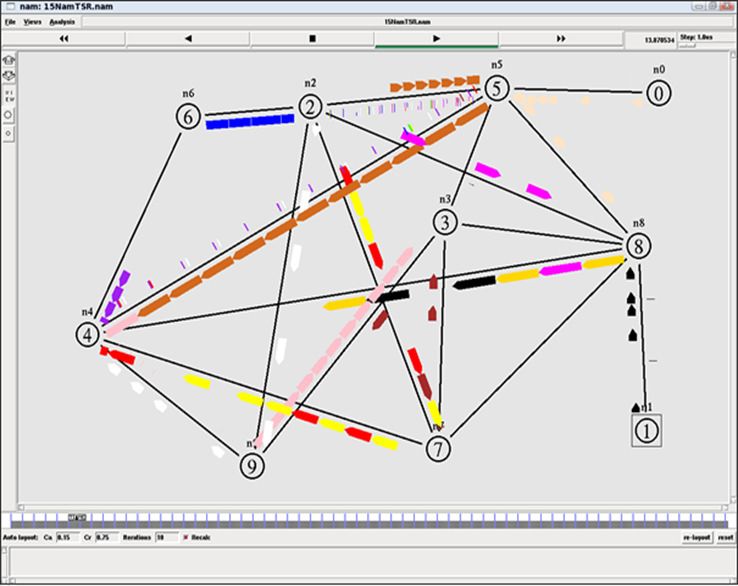
(IJACSA) International Journal of Advanced Computer Science and Applications,
                                                                                                                Vol. 13, No. 1, 2022

    Our proposed scheme, named Enhanced Traffic Split                            •    λ2 : the arrival rate for path 2
Routing (E-TSR), is bas on algorithm Traffic Split Routing
(TSR) [24] [25] which offer a good objective on load bal-                    So, the average residence time across the two paths is:
ancing inside a network. Enhanced Traffic Split Routing try to                                       λ1 n       λ2 n
distribute homogeneously the traffic on the network and offer a                               T2 =            +                            (5)
                                                                                                     λ µ − λ1   λ µ − λ2
balanced sharing of traffic. Indeed, with E-TSR, the maximum
possible of links are used to balance the traffic on the network.            If we find cases where T1 < T2 then we can state that the
                                                                             shortest path does not give precisely the best delay. We can
    We present in what follows, algorithm 1, the heuristic of                say that:
traffic distribution used which is an enhanced algorithm based
on [24] [25]. To begin, it is interesting to note that is not always                                   ρ1     m ρ2        ρ
optimal to use the shortest path between a pair of nodes ”i”                             T1 ≤ T2 ⇔          +          ≤                   (6)
and ”j”. Accordingly, we will use a model of an M/M/1                                                1 − ρ1   n 1 − ρ2   1−ρ
queue. Suppose that between two nodes ”i” and ”j” we have                    Where,
two paths: the shortest path of length ”n” and another longer                                                   λ1
                                                                                                         ρ1 =                              (7)
path of length m > n .                                                                                          µ
    To begin with, we assume that we have a first path
calculated by the shortest path algorithm. This path links                                                      λ2
                                                                                                         ρ2 =                              (8)
a source ”i” to a destination ”j” and uses ”n” links. We                                                        µ
assume that each link in the path from ”i” to ”j” is modeled
by an independent M/M/1 queue (Kleinrock independence
assumption) as illustrated on Fig. 1.                                                                     ρ ≥ ρ1                           (9)
Now suppose that the traffic is shared between the path with
”n” hops and that of ”m” hops. Consider the following
variables:                                                                                                ρ ≥ ρ2                          (10)
   ρ: use of the link,
when all the traffic is offered to the first path only (the shortest
path) we have the average residence time on a link:                                                    ρ = ρ1 + ρ2                        (11)
                                     1                                       In the case where m < n, then the inequality 6 gives us:
                             T =                                       (2)
                                    µ−λ
Therefore, the use of the link                                                                             n(1 − ρ2 )
                                                                                                  m≤                                      (12)
                                   λ                                                                    (1 − ρ1 )(1 − ρ)
                                ρ=                                     (3)
                                   µ                                              The inequality 12 shows that the number of hops in the
Since this path is composed of ”n” independent links, the                    path should be small and not greater than a certain constant.
average residence time in the path is modeled by the following               Additionally, this inequality clarifies that when the shorter path
formula:                               n                                     is overloaded (maximum link utilization), using another longer
                    T1 = n × T =                           (4)               path to route traffic can be useful in order to reduce the wait
                                     µ−λ                                     time. Moreover, we can deduce that the number of hops in
                                                                             the longest path decreases when the load offered to this path
       Shortest path (n hops)                                                (ρ2 ) increases. In particular, in the case where the traffic is
                                                                             distributed between the shortest path and the longest one (ρ1 =
                                                                             ρ2 ), it suffices to have m < n/((1 − ρ)) to reduce the waiting
              i
                                                                             time by traffic distribution. For example, if ρ = 80%, then we
                                                                             must have m < 5n. That is, the number of hops in the longest
                                                                             path should not exceed 5 times the number of hops in the
                                                             j               shortest path.

                                                                                            IV.   R ESULT AND D ISCUSSION
                                                                                 This section is devoted to evaluating the performance and
                                                                             quality of services resulting from the Enhanced Traffic Split
                  Traffic Split (m hops)                                     Routing (E-TSR) algorithm by comparing the results with
 Fig. 1. Shorter Path Versus Sharing of Traffic Through Disjointed Paths.    those obtained with Traffic Split Routing (TSR) [25] and the
                                                                             Shortest Path Routing (SPR). In order to be able to evaluate
                                                                             these three algorithms, various simulations were carried out
    If we share the traffic between the two paths; the first made            using the NS-2 simulation platform [26].
up of ”n” hops and the second of ”m” hops, we have the
variables:                                                                      To begin, we attempt to give an overview of different
                                                                             parameters related to evaluate the performance of our proposed
   •     λ1 : the arrival rate for path 1                                    scheme. Then, we will present more closely the NS-2 tool as
                                                                 www.ijacsa.thesai.org                                         777 | P a g e
(IJACSA) International Journal of Advanced Computer Science and Applications,
Vol. 13, No. 1, 2022
Algorithm 1 Enhanced Traffic distribution heuristic
Input : Ls the number of times a link S appears in a VPN tree
1: procedure HEURISTIC P ROCEDURE
2: Ls ← 0 :Definition of a link Variable
3: n ← 0 :Definition of the number of nodes on the network
4: loop: waiting for a new Virtual Private Network connection demand from any network’s node
5: Complete (or Generate) a path (tree) coupling all the new Virtual Private Network and avoiding links whose Ls > n
6: if path is icomplete then
7: n ← n + 1 and goto step 5
8: else
9: Ls ← Ls log(Ls ) + 1 for all the links of the new generated tree and goto step 3.
10: end if
11: end procedure
well as the network model used to perform different scenarios
to be simulated under NS-2.
The rest of this section will highlights the QoS parameters
used to evaluate the three heuristics: the enhanced traffic
distribution (TSR, Traffic Split Routing), the traffic distribution
(TSR, Traffic Split Routing), and the shortest path (SPR,
Shortest Path Routing). All the simulation parameters are
given in Table I. Our simulations are performed using the
TABLE I. S IMULATION PARAMETERS
Parameters Values
Simulator name NS-2
Node’s number 24 nodes
Tree’s link capacity 100 Mb/s
Transmission delay 10 ms
Source’s number of the generic tree 4-24 nodes
Simulation Time 2000 seconds
Application type used on the simulations FTP
Packet size 1 KB
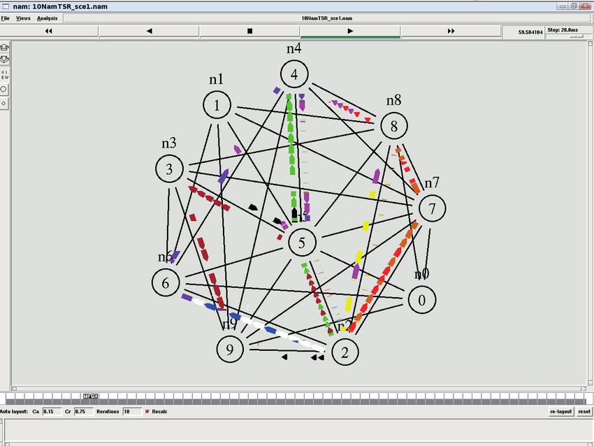
Fig. 2. Enhanced TSR Traffic.
NS-2 network simulator. For accuracy and compliance, all
simulations are performed Twenty times for each scenario. All
simulations are performed to study the behavior of the three
routing algorithms; E-TSR, TSR, and SPR. All simulations are
generated with different random number seeds and the results
are averaged over all the outcomes. Fig. 2, Fig. 3, and Fig. 4
illustrate an example of network scenario used in performance
study for the three heuristics E-TSR, TSR, and SPR.
Fig. 4 illustrates the scenario using Shortest Path traffic al-
gorithm. From this figure, we suppose that the traffic is sent
from node 2 to the destination node 4. We see that the node
named 6 used as a Steiner node and all traffic is focused on
the shortest path (from node 2 to node 6, and from node 6 to
node 4). On the other hand, Fig. 2 illustrates the scenario of
the Enhanced Traffic Split Routing. From this Figure we can
see that the traffic is shared equitably between different paths.
Indeed, the traffic sent from node 2 and has as destination node
4 has taking different paths (from node 2 to node 6, from node
2 to node 7, etc.). with this approach, we can see that we use
maximum links on the network. Fig. 3. TSR Traffic.
A. Average Reception Data Rate
Fig. 5 illustrates the average data rate reception of the of source VPNs. Indeed, in the case of 6 source VPNs we
three algorithms, E-TSR, TSR and SPR. As we can see, the have 5.9 Mbps with E-TSR heuristic, 5.58 Mbps with TSR
Fig. 5 shows the average data rate as a function of the number heuristic while the average throughput with SPR is 5.23 Mbps.
www.ijacsa.thesai.org 778 | P a g e(IJACSA) International Journal of Advanced Computer Science and Applications,
Vol. 13, No. 1, 2022
to 12 sources, SPR and E-TSR have almost the average error
rate, 9.6 × 10⁻⁴ and 11.5 × 10⁻⁴ , respectively.
This rate increases to reach 43 × 10−4 packets loss with
SPR routing technique, 30 × 10−4 packets lost with TSR
routing technique, and 27 × 10−4 packets lost with E-TSR
routing heuristique for 24 source VPNs.
Furthermore, as the number of source VPNs increase, the
gap between SPR, TSR, and E-TSR increases and as we can
see E-TSR provides less packet error rate. Indeed, with a
shortest path routing technique all the traffic takes the same
path which lead to a huge traffic on some links and then more
error rate. However, with distributed traffic routing technique
the traffic flow is sent over the network moderately over all
links.
Furthermore, using a traffic distributed technique, packet
Fig. 4. SPR Traffic.
have low chance to enter on overloaded queues, thus dropping
packets will minimized and rejecting packets will be decreased.
On the other site, with shortest path routing technique, there
is a high probability the traffic takes the same path leading to
subsequently, with 16 source VPNs, the average throughput a queue overload and then increase rejected packets.
with E-TSR is equal to 5.35 Mbps while it is equal to 3.93
Mbps with SPR algorithm. We see also that the gap on the
average data rate increase with the number of source VPNs
and the E-TSR algorithm offer good throughput compared to
TSR and SPR algorithms. This is due to algorithm properties.
Indeed, with SPR, all the traffic is focused on the shortest
path while with E-TSR the traffic is divided between the
maximum number of links on the network. Moreover, the
use of maximum links allowed networks to offer a higher
throughput especially for networks with large traffic, unlike
to shortest path algorithm which focused only on some links
(shortest link) which lead to some links to become overloaded,
leaving others unused. This had an influence on the flow and
Fig. 6. Average Packet Loss Rate.
then on the error rate.
C. Average End-to-end Delay
In this section we examine the mean delay to send a
packet from one source to a destination. This delay is given
according to the number of source VPNs on the network. Fig. 7
shows that the delay of three heuristics E-TSR, TSR, and SPR
increases linearly with the number of source VPNs.
Moreover, Enhanced Traffic Split Routing algorithm ex-
hibit a brief variation on delay compared to the Shortest Path
Routing Algorithm. From Fig. 7 we remark that SPR has a
Fig. 5. Average Data Rate Reception. delay around of 30 ms with 6 source VPNs. By increasing the
number of source VPNs we see that E-TSR offer less end-to-
end delay compared to TSR and SPR. In fact, E-TSR and TSR
look increase on logarithmic fashion compared to SPR.
B. Packet Loss Rate It is clear to see that in the case of 16 source VPNs the aver-
age end-to-end delay is equal to 25.32 ms for E-TSR algorithm
Fig. 6 illustrates the packet loss rate as a function of whereas it is equal to 27 ms for TSR algorithm, and 39 ms
number of source VPNs for each routing technique E-TSR, for SPR algorithm. Table II gives an overview of the measured
TSR and SPR. As shown in this figure, with low number of values related to the mean delay for three routing algorithms.
source VPNs average error rate with E-TSR and TSR become The gap on the end-to-end delay increases as number of source
more frequent due to the fact that the routing techniques must VPN increase. Our observations, for instances imply that when
search new link every time there is a new source VPN. It can the network deploy a traffic distributed technique offer more
be noticed that when the number of VPN sources increases chance of using a less queue memory which means packets
www.ijacsa.thesai.org 779 | P a g e(IJACSA) International Journal of Advanced Computer Science and Applications,
Vol. 13, No. 1, 2022
TABLE II. G AP M EAN D ELAY to provide better low packet loss rate and data rate by using
72% of network links compared to shortest path routing
# VPNs Mean delay SPR (ms) Mean delay TSR (ms) Mean delay E-TSR (ms) algorithm which uses only 44% of network links.
4 24 25 23
6 30 26 23.56
8 34 26 23.58 As a future work, we plan to design and implement the
10 36 26 23.99 proposal experimentally in order to study these factors practi-
12 37 26 24 cally and exploring the potential of utilizing enhanced traffic
14 39 26 24.12
16 39 27 25.32 split routing on real-time multimedia and VoIP applications.
18 40 27 25.64
20 40 27 25.87
22 41 27 25.9
24 41 28 26 R EFERENCES
[1] R. M. Hicks, “Plan for always on vpn,” in Implementing Always On
VPN. Springer, 2022, pp. 7–20.
sent on different links have more chance of going through [2] H. H. Elkarash, N. M. Elshennawy, and E. A. Saliam, “Evaluating qos
small queues and therefore a small delay variation as shown using scheduling algorithms in mpls/vpn/wimax networks,” in 2017 13th
on Fig. 8. International Computer Engineering Conference (ICENCO). IEEE,
2017, pp. 14–19.
[3] A. Black, T. Bui, S. Jenni, V. Swaminathan, and J. Collomosse, “Vpn:
Video provenance network for robust content attribution,” in European
Conference on Visual Media Production, 2021, pp. 1–10.
[4] T. Alam and K. Hamid, “Implementation of dynamic multipoint vpn
over ipsec for secure enterprise network,” Ph.D. dissertation, IIUC
Central Library, 2018.
[5] A. BAHNASSE and N. E. KAMOUN, “Policy-based automation of
dynamique and multipoint virtual private network simulation on opnet
modeler,” International Journal of Advanced Computer Science and
Applications, vol. 5, no. 12, 2014.
[6] F. Bensalah and N. El Kamoun, “Novel software-defined network
approach of flexible network adaptive for vpn mpls traffic engineering,”
Fig. 7. Mean Delay. Int. J. Adv. Comput. Sci. Appl, vol. 10, no. 4, pp. 280–284, 2019.
[7] M. Iqbal and I. Riadi, “Analysis of security virtual private network (vpn)
using openvpn,” International Journal of Cyber-Security and Digital
Forensics, vol. 8, no. 1, pp. 58–65, 2019.
[8] T. Vitalii, B. Anna, H. Kateryna, and D. Hrebeniuk, “Method of
building dynamic multi-hop vpn chains for ensuring security of terminal
access systems,” in 2020 IEEE International Conference on Problems
of Infocommunications. Science and Technology (PIC S&T). IEEE,
2020, pp. 613–618.
[9] Q. Jin, Q. Guo, M. Luo, Y. Zhang, and W. Cai, “Research on high
performance 4g wireless vpn for smart factory based on key tech-
nologies of 5g network architecture,” in 2020 International Wireless
Communications and Mobile Computing (IWCMC). IEEE, 2020, pp.
1443–1447.
[10] Y. Christov, “Building personal virtual private networks in public cloud
platforms,” Industry 4.0, vol. 5, no. 3, pp. 112–113, 2020.
[11] A. Bahnasse, M. Talea, A. Badri, F. E. Louhab, and S. Laafar, “Smart
hybrid sdn approach for mpls vpn management on digital environment,”
Fig. 8. Flow of Sent Data. Telecommunication Systems, vol. 73, no. 2, pp. 155–169, 2020.
[12] K. Gaur, A. Kalla, J. Grover, M. Borhani, A. Gurtov, and M. Liyanage,
“A survey of virtual private lan services (vpls): Past, present and future,”
Computer Networks, p. 108245, 2021.
V. C ONCLUSION AND F UTURE W ORK
[13] T. Takeda, R. Aubin, M. Carugi, I. Inoue, and H. Ould-Brahim,
In this paper, we proposed an enhanced traffic split routing “Framework and requirements for layer 1 virtual private networks,”
RFC 4847, April, Tech. Rep., 2007.
algorithm. Such algorithm is compared with shortest path
algorithm. Simulations were performed using NS-2 to analyze [14] S. M. Rosu, M. M. Popescu, G. Dragoi, and I. R. Guica, “Virtual
enterprise network based on ipsec vpn solutions and management,”
the functionality and performance of the proposed algorithm International Journal of Advanced Computer Science and Applications,
in terms of average data rate, packet loss rate, and average vol. 3, no. 11, 2012.
end-to-end delay. [15] S. T. Aung and T. Thein, “Comparative analysis of site-to-site layer
2 virtual private networks,” in 2020 IEEE Conference on Computer
The results show that Enhanced Traffic Splitting Routing Applications (ICCA). IEEE, 2020, pp. 1–5.
algorithm provides least values on packet loss rate and average [16] B. Wen, G. Fioccola, C. Xie, and L. Jalil, “A yang data model for layer
end-to-end delay compared to Shortest Path Routing and 2 virtual private network (l2vpn) service delivery,” Internet Eng. Task
legacy Traffic Splitting Routing algorithm. Force, Fremont, CA, USA, Rep. RFC, vol. 8466, 2018.
[17] K. Arai, “Routing protocol based on floyd-warshall algorithm allowing
Also, simulation results show that TSR provides better maximization of throughput,” International Journal of Advanced
performance in term of average data rate. So, it is concluded Computer Science and Applications, vol. 11, no. 6, 2020. [Online].
that enhanced traffic split routing algorithm has the capability Available: http://dx.doi.org/10.14569/IJACSA.2020.0110655
www.ijacsa.thesai.org 780 | P a g e(IJACSA) International Journal of Advanced Computer Science and Applications,
Vol. 13, No. 1, 2022
[18] H. Gunleifsen, T. Kemmerich, and V. Gkioulos, “Dynamic setup of “Introduction to algorithms,” 1997.
ipsec vpns in service function chaining,” Computer Networks, vol. 160, [23] N. Shacham, “Multipoint communication by hierarchically encoded
pp. 77–91, 2019. data,” in [Proceedings] IEEE INFOCOM ’92: The Conference on
[19] B. Waxman, “Routing of multipoint connections,” IEEE Journal on Computer Communications, 1992, pp. 2107–2114 vol.3.
Selected Areas in Communications, vol. 6, no. 9, pp. 1617–1622, 1988. [24] A. Meddeb, “Benefits of multicast traffic split routing in packet switched
[20] E. Akin and T. Korkmaz, “An efficient binary-search based heuristic for networks,” in 2004 IEEE International Conference on Communications
extended unsplittable flow problem,” in 2017 International Conference (IEEE Cat. No.04CH37577), vol. 4, 2004, pp. 2019–2023 Vol.4.
on Computing, Networking and Communications (ICNC). IEEE, 2017, [25] A. Berguiga, A. Harchay, A. Massaoudi, and R. Khdhir, “A new traffic
pp. 831–836. distribution routing algorithm for low level vpns,” International Journal
[21] F. U. Islam, G. Liu, and W. Liu, “Identifying voip traffic in vpn of Advanced Computer Science and Applications, vol. 11, no. 12, 2020.
tunnel via flow spatio-temporal features,” Mathematical Biosciences and [26] K. R. Fall and K. Varadhan, “The ns manual (formerly ns notes and
Engineering, vol. 17, no. 5, pp. 4747–4772, 2020. documentation,” 2002.
[22] R. L. R. Thomas H. Cormen, Charles E. Leiserson and C. Stein,
www.ijacsa.thesai.org 781 | P a g eYou can also read