An Arduino-based, low-cost imaging incubator for extended live cell imaging - arXiv
←
→
Page content transcription
If your browser does not render page correctly, please read the page content below
Engineering and Laboratory Note                                                                                         Applied Optics   1

                                                   An Arduino-based, low-cost imaging incubator for
                                                   extended live cell imaging
arXiv:2206.02542v1 [physics.ins-det] 28 May 2022

                                                   V INCENT M. ROSSI1,* , K ATHERINE C. DAVIDSON1 ,                       AND    L AUREN E. M OORE2
                                                   1 Department of Physics and Astronomy, Washburn University, 1700 SW College Ave, Topeka, KS 66621, USA
                                                   2 Department of Biology, Washburn University, 1700 SW College Ave, Topeka, KS 66621, USA
                                                   * Corresponding author: vincent.rossi@washburn.edu

                                                   Compiled June 7, 2022

                                                         In order to image live cells for prolonged periods of time, an Arduino-based, low-cost imaging incubator
                                                         was constructed. The imaging incubator keeps cells viable by controlling for temperature and CO2 in
                                                         order to maintain physiological conditions for cells during imaging. All devices and parts employed in
                                                         the build were typical maker-type components in order to minimize the cost of the imaging incubator.
                                                         The imaging incubator allows for real-time imaging of live cells exposed to any desired perturbation or
                                                         stimulus. As a proof of the system’s functionality, cells are imaged over 24 hours while remaining viable
                                                         in the imaging incubator. © 2022 Optica Publishing Group
                                                         http://dx.doi.org/10.1364/ao.XX.XXXXXX

                                                   1. INTRODUCTION                                                            tem incorporated onto their stages. Systems that are compact
                                                                                                                              enough to insert into an incubator start around $20,000 and can
                                                   Keeping living cells viable while imaging over moderate time               have prices above $40,000.[6, 7] These systems also have the dis-
                                                   intervals can be precarious, let alone for an extended period of           advantages of taking up the majority of incubator space and
                                                   time.[1] The authors were interested in imaging the real-time              possibly exposing neighboring cells in the incubator to unde-
                                                   response of mammalian cells exposed to different stimuli for               sired light. To negate these disadvantages, these units would
                                                   up to 24 hours. Such prolonged time frames for imaging live                require their own, dedicated incubator, therefore adding thou-
                                                   cells should permit the monitoring of cells through the cell cy-           sands of dollars to their total cost. As an alternative, there are
                                                   cle while exposed to different stimuli. The desire to image mam-           many bench-top microscopes available on the market with in-
                                                   malian cells for an entire day necessitates the need to keep cells         cubator stages integrated into their design. While these scopes
                                                   viable over that time frame via regulation of temperature and              don’t take up incubator space, many are not priced as complete
                                                   CO2 . As a response to this need, the authors have created an              systems, requiring add-on units in order to achieve live cell
                                                   Arduino-based, low-cost imaging incubator designed to keep                 imaging. In the worst case scenario, having to purchase addi-
                                                   cells viable for prolonged periods of time while held on the sam-          tional units in order to achieve live cell imaging can double the
                                                   ple stage of a custom, bench-top imaging device.                           units’ base pricing. These scopes start at around $12,000 and
                                                       Real-time, prolonged imaging of cells affords researchers dy-          the complete systems can run over $50,000.[8, 9]
                                                   namic information, including changes in cell morphology, re-                  The imaging incubator presented here was designed and
                                                   sponses to various stimuli or reagents, cell proliferation, motil-         constructed using a minimal research budget. In order to keep
                                                   ity and cell tracking.[2, 3] Retail devices that are available for         costs low, all devices, components and supplies used in the con-
                                                   prolonged, live cell imaging are generally of two sorts: stages            struction of the imaging incubator were acquired from typical
                                                   that can be added to any microscope or complete imaging sys-               maker sources, hardware stores and online retailers. This be-
                                                   tems. Stages that can be added to any microscope have the ad-              gins with the use of an Arduino Uno[10] in place of a typical
                                                   vantage of being utilized for any imaging application needed,              DAQ for interfacing with devices. All of the hardware, sup-
                                                   across various platforms. Environmental control stages that can            plies, components and parts needed to build the imaging incu-
                                                   be used on any microscope start around $450, but those less                bator were purchased for under $350. At this price, the imaging
                                                   expensive units only control for temperature and not CO2 .[4]              incubator presented in this paper starts at less than 10% of the
                                                   Stages that can be added to any microscope that also control for           cost of sample stages and closer to 1-2% of the cost of complete
                                                   CO2 have starting prices above $12,000.[5]                                 imaging systems on the market with similar features, affording
                                                       Complete imaging systems that allow for environmental                  researchers a savings of thousands to tens of thousands of dol-
                                                   controls come in two varieties: those that can be placed within            lars.
                                                   an existing incubator and those that have an incubation sys-                  While the Arduino IDE[11] could be employed for monitor-
Engineering and Laboratory Note                                                                                               Applied Optics         2

ing and control of temperature and CO2 levels, the authors in-
stead relied upon LabVIEW (National Instruments, Austin, TX)             $8($'%+1-*&'(#-@&'-6+71$#-+%4-(,7/%2
for device control. This decision was made because of the need                                                  .$+($'-
to also control optical and imaging devices associated with the                                                  ,%/(
custom microscope itself. By writing the imaging incubator                                                                     .:*&4$')/6-%$$41$
control program via LabVIEW, both the imaging incubator and             !"! 4$1/?$':-(,7/%2                                            !"! #$%#&'
imaging device control are integrated into a single program.
Software costs are not included in the cost of the imaging in-
                                                                                                                          /)+2/%2-6.+)7$'
cubator as the lab already had a license for LabVIEW. In lieu of
                                                                                       =-4'/*-#:#($)
using LabVIEW, the open source Arduino IDE could be imple-                                                                   #+)*1$-#(+2$
mented for control of the imaging incubator at no cost.
   The remainder of this paper covers the design and imple-                                                                    &,(1$(-7&8
mentation of the Arduino-based imaging incubator. In Sec. 2,                                                                 9'$1+:-)&4,1$-
the design and build of the imaging incubator is detailed. This                                                                  /%#/4$;
includes the enclosure itself, along with the various control sys-
                                                                                                                            3'4,/%&-5%&-
tems and hardware. The software used for controlling the dif-                                                              )/6'&6&%('&11$'
ferent components and systems is covered in Sec. 3. Finally,                                                                            0+'1/%2(&%-
to demonstrate the imaging incubator’s functionality, sample                                                                            ('+%#/#(&'
images of mammalian cells acquired via the imaging incuba-                                                                  ($)*$'+(,'$-#$%#&'
tor over 24 hours are presented in Sec. 4, before giving con-
cluding remarks (Sec. 5). A list of all parts and components is
                                                                      Fig. 1. The imaging incubator as viewed from the front (left
summarized in the Appendix, along with block diagrams from
                                                                      pane), inside (middle pane) and top (right pane). Relevant
the LabVIEW program used to automate the imaging incubator.
                                                                      components are labeled.
The latter is also available via the article’s online supplemental
materials.

2. SYSTEM DESIGN                                                      output, a translucent enclosure eliminated the need to cut opti-
While a compact, stage-top design would have been preferred,          cal ports through the enclosure. The transparent enclosure also
this led to issues providing heat from an external unit to a com-     permits the imaging incubator to have uses for additional, fu-
pact space. For ease of design, the imaging incubator was there-      ture imaging devices which could have different incoming and
fore designed as an enclosure over a portion of the custom mi-        outgoing beam paths.
croscope that would also completely enclose the heating unit.
                                                                          Right-angle brackets were used in order to bolt the sides of
The imaging incubator (Fig. 1) consists of the following ele-
                                                                      the enclosure together. The front panel was cut at the top and
ments: the enclosure, an Arduino Uno microcontroller for inter-
                                                                      bottom in order to create a door for access. The top of the front
facing, temperature and CO2 control systems and a fluid system
                                                                      panel and door were joined together with cabinet hinges and a
consisting of a drip system for replenishing media for cells as it
                                                                      cabinet knob was added to the front of the door for access. The
evaporates. These elements and systems will be covered in this
                                                                      bottom portion of the front panel and the door were outfitted
section, while software for controlling the system devices will
                                                                      with a magnetic cabinet door catch in order to hold the incuba-
be discussed in Sec. 3. A manually controlled UV lamp (CTUV-
                                                                      tor door closed when in use. Two through holes were drilled
6WTIMERUVC, Aopu Lighting Co) is also installed at the top
                                                                      in the top sheet prior to assembly and pair of 1/2” water tight
of the enclosure for sterilization purposes. Sterile tissue culture
                                                                      conduit connectors were mounted in order to serve as tight fit-
practices were observed when using the imaging incubator, as
                                                                      tings through which to pass cables and tubing. A third through
would be done for any incubator.
                                                                      hole was drilled for installation of a 1/4” hose barb in order to
                                                                      port CO2 via tubing. To improve the seal, o-rings were used at
A. Enclosure
                                                                      the junctions between the through holes in the cover and the
The enclosure (24′′ × 11 1/2′′ × 18′′ ) for the Arduino-based         conduit connectors and hose barb.
imaging incubator was built around the sample stage of a cus-
tom built imaging system. In order to fully enclose the sam-              The enclosure was placed atop the optical bench, with strips
ple, additional optical elements needed to be enclosed within         of silicone rubber sheets (1/16” thick) placed in between the
the imaging incubator as well. The enclosed optical elements          bench top and enclosure in order to create an airtight seal. Ad-
included mirrors for redirection of the incident light and the        ditional strips of silicone rubber were placed inside the imaging
microscope objective. The remainder of the microscope’s opti-         incubator across the seams between the incubator door and en-
cal elements and components were all outside of the imaging           closure in order to improve the seal at the seams, although this
incubator, including the light source, collimating and imaging        only provided a small improvement. Strips of rubber sheets
lenses and camera. Clear acrylic plexiglass sheets (1/8” thick)       were also placed atop the vertical walls of the enclosure to cre-
were used for the four sides and lid of the imaging incubator.        ate a seal with the top panel, again made from the same acrylic
Opaque or black acrylic sheets could have been used in lieu of        sheet as the walls of the enclosure. A bead of caulking was also
clear sheets, but since the microscope’s camera was not housed        used to join the gaskets and enclosure walls and the corners
within the imaging incubator, light contamination would have          of the enclosure where the walls met in order to ensure the best
still been an issue for the imaging system. Whereas the use of an     seal possible for the imaging incubator. Caulking was also used
opaque enclosure would necessitate the need for cutting ports         to seal the gaps between the conduit connectors, cables and tub-
and then resealing them with glass windows for light input and        ing.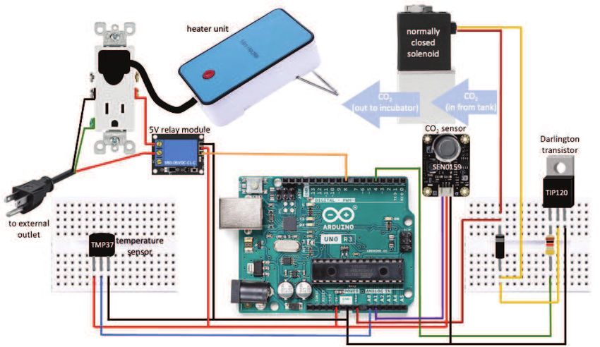
Engineering and Laboratory Note Applied Optics 3
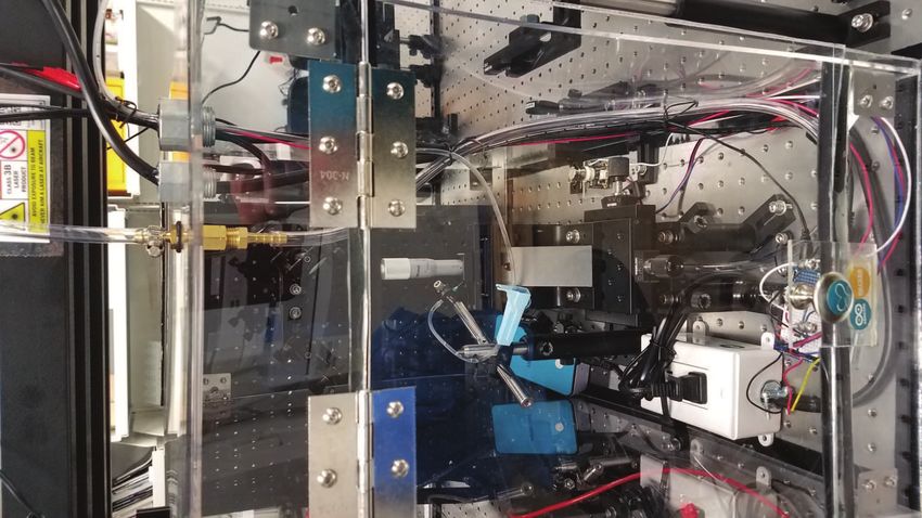
B. Temperature & CO2 Control Systems pressurized gas from perturbing the sample or increasing the
In lieu of using a DAQ in order to interface between the loss of media, an additional length of tubing was added within
the imaging incubator in order to redirect the delivery of CO2
controlling computer and devices associated with the imag-
away from the sample stage. In addition, the placement of the
ing incubator, an Arduino Uno microcontroler was used as a
tubing’s output nozzle was placed near the heating unit’s fan
low-cost alternative. The imaging incubator combines multi-
in order to promote mixing of CO2 throughout the imaging in-
ple systems that can be found via online Arduino and maker
communities.[12–14] cubator.
While the Arduino can be powered via the USB 2.0 cable that
The temperature control system (Fig. 2) begins with an ana- links it to the computer, the many devices controlled via the Ar-
log temperature sensor (TMP37FT9Z, Analog Devices) which duino tax its maximum output. In particular, the solenoid that
is monitored via an analog input on the Arduino. Input volt- serves as the automated valve for CO2 injection requires greater
ages from the temperature sensor are converted to degrees Cel- current and voltage outputs than can be provided by the Ar-
sius. Optimally, mammalian cells like to be held at 37o C, so duino alone. An external power cable connects the Arduino di-
when the temperature measurement drops below a threshold rectly to an external electrical outlet, which supplies additional
of 35o C, a mini, corded desktop heater (WY-H1, Ucan) plugged power for the devices via the Vcc pin. Even with the external
into a 110V outlet is switched on via a 5V relay module (SRD- power supply to the Arduino, a Darlington transistor (TIP120,
05VDC-SL-C, Tolako) controlled by one of the digital outputs onsemi) is needed in order to amplify the input to the solenoid
of the Arduino.[12] The digital output to the relay module is (Fig. 2).[14]
held high while the temperature in the incubator increases and
doesn’t switch to low until the temperature exceeds 37o C. At
C. Fluid System
that point, power to the heating unit is turned off. The inter-
nal temperature of the imaging incubator was confirmed via In order to keep cells viable during imaging, they must also
a hand held infrared thermometer (Lasergrip 1080, Etekcity). be submerged under adequate media as both a nutrient source
The desired temperature of 37o C was used as the upper thresh- and a means of preventing cellular dehydration. An imaging
old to turn off the heating unit because the ambient heat built chamber (QR-40HP, Warner instruments) holds the coverslip to
up in the unit will still dissipate within the enclosure, causing which cells are adhered, along with a few mL of media. Note
the internal temperature to continue to rise. Setting a higher that the cost of the imaging incubator noted in the introduction
threshold than 37o C allowed temperatures to climb beyond the does not include that of the imaging chamber, which was al-
desired temperature range. Keeping the 35o C and 37o C lower ready in the lab’s possession. Similar imaging chambers could
and upper thresholds respectively gave a stable temperature be made in-house via a 3D printer in order to save costs.
range, keeping the temperature system from cycling excessively. A water bath is generally used at the base of standard tis-
Excessive cycling of the heating unit was also avoided by us- sue culture incubators in order to keep humidity levels high
ing the average of one hundred temperature measurements in an prevent media from evaporating. The imaging incubator
quick succession, thereby mitigating fluctuations in the temper- does not have this luxury, as increased humidity within the
ature measurements due to noise within the system. imaging incubator would increase the likelihood of condensa-
tion building upon optical elements, thereby degrading image
Similar to the temperature control system, the CO2 con- quality. Furthermore, increased humidity within the imaging
trol system (Fig. 2) has an analog CO2 gas sensor (SEN0159,
incubator could also affect the functionality of electronic com-
DFROBOT) connected to an analog input on the Arduino.[13] ponents housed within the imaging incubator. Evaporation of
The CO2 sensor needs to be calibrated to set the optimal range media within the imaging incubator is unavoidable given the
for CO2 concentrations—typically 5%CO2 for mammalian cells. internal heating unit and temperature requirements to maintain
The analog device was calibrated using a fyrite gas analyzer kit cell viability. Evaporation of media in the imaging incubator
(Model 10-5000, Bacharach), borrowed from the university’s Bi- has two negative side effects, the first being the possible build
ology Department. The analog output of the device decreases up of condensation on optical elements as already mentioned
along an exponential decay function as CO2 concentrations in- and the second being the depletion of cells’ media. Media that
crease (Fig. 3). When CO2 levels drop below the lower thresh- has evaporated away from the cell imaging chamber is then re-
old of 4.8%CO2 , the Arduino triggers the activation of a 12V plenished via a gravity fed 15 drops/mL I.V. drip system, with
two-way normally closed electric solenoid air valve (2V025-08, the drip rate controlled using a variable latch.
AOMAG), which allows pressurized CO2 to supply the imag-
ing incubator. When the concentration of CO2 climbs above
the upper threshold of 5.2%CO2 , the solenoid is deactivated, 3. SOFTWARE DESIGN
thereby closing its valve and ceasing the supply of CO2 to the in- System automation was an essential requirement of the sys-
cubator. The solenoid is the only major electrical component of tem’s software design; our goal of keeping cells viable for 24
the imaging incubator that is not housed within the enclosure. hours of imaging meant that the system would be left unat-
As with the temperature control system, CO2 concentrations tended for extended periods of time. As such, we decided to
were determined by averaging one hundred measurements in control the Arduino—and therefore the associated hardware
quick succession; the lower and upper thresholds used here devices—using LabVIEW and the LINX add-on package for
gave a stable range of CO2 concentrations, keeping the CO2 con- LabVIEW.[15] This way, the imaging incubator and imaging
trol system from cycling excessively. device programming and automation could be integrated for
A 75 lb CO2 tank in the lab that is used for a standard tissue ease of use. As an alternative, the Arduino IDE could also have
culture incubator was equipped with a two-way gas manifold been used to program the imaging incubator separately from
in order to supply the imaging incubator simultaneously. The the imaging system program. But again, we opted to run a sin-
CO2 port lies above the sample stage, which directed pressur- gle program instead of having two separate programs compet-
ized gas at the sample during imaging. In order to prevent the ing for computational resources.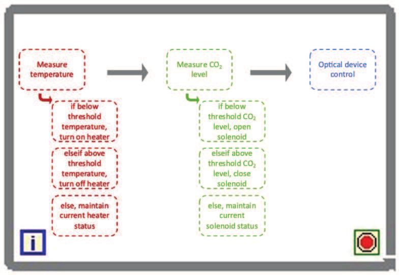
Engineering and Laboratory Note                                                                                        Applied Optics   4

Fig. 2. A diagram of the temperature (left) and CO2 (right) control systems.

            16                                                            by the LINX add-on in order to read input voltages via the Ar-
                                                  calibration data
                                                                          duino. With any of the analog or digital read/write VI’s in the
            14                                    exponential fit
                                                  target CO 2 range       LINX add-on, the appropriate Arduino pin number correspond-
            12                                                            ing to the wired component(s) must be provided. When temper-
                                                                          atures outside of the range of the lower or upper temperature
            10                     % CO 2 = 686e-3.7    V
                                                                          thresholds are read by the Arduino, the program then triggers
   % CO 2

                                                                          the appropriate on or off state of a digital Arduino pin via the
            8                                                             Digital Write.vi, thereby controlling the 5V relay module and
                                                                          by it, the external power outlet supplying the heating unit (Fig.
            6
                                                                          2).
            4                                                                 The CO2 control system first calls to the Analog Read.vi in
                                                                          order to read the voltage input from the CO2 sensor via the Ar-
            2                                                             duino. When the soleniod needs to be opened or closed in order
                                                                          to control CO2 injection, the Digital Write.vi is implemented in
            0                                                             order to turn the base of the TIP120 Darlington transistor on
                 1      1.5             2              2.5            3
                                        V                                 or off via a high or low digital output, respectively (Fig. 2).
                                                                          When the digital output connected to the base is active, the cur-
Fig. 3. Calibration of the analog CO2 sensor.                             rent gain of the Darlington transistor is sufficient to power the
                                                                          solenoid.
                                                                              After controlling the environmental systems of the imaging
   To initialize the Arduino for LabVIEW, the MakerHUB LINX               incubator, the program then goes on to control the imaging sys-
Firmware Wizard was used to install the appropriate driver.               tem itself (not detailed here). The control sequencing (Fig. 4) is
Then in LabVIEW, communication with the Arduino is made                   contained within a while loop with a 1 second delay between
simple via the LINX add-on. To begin, communication is set up             iterations so as to prevent the control systems from cycling ex-
with the Arduino via the Open.vi provided by the LINX add-                cessively. The while loop maintains system operations until the
on—the .vi file extension stands for Virtual Instrument in Lab-           system is either halted manually via a stop button on the pro-
VIEW.                                                                     gram front panel, or until the experiment is completed. At that
   The program first checks the temperature within the imag-              point, all digital outputs from the Arduino are set to low via the
ing incubator using the TMP3x.vi provided by the LINX add-on.             Digital Write.vi so as to turn off the respective devices and com-
The TMP3x.vi is written to operate three different temperature            munications with the Arduino are terminated via the Close.vi,
sensors (the TMP35, TMP36 and TMP37), so the appropriate                  again provided by the LINX add-on.
sensor needs to be selected in the drop down provided (in this                The system was run using a Dell Precision T3500 worksta-
case the TMP37) in order to call to the appropriate calibration.          tion (64-bit, ×8 Intel Xeon CPU W3550 @ 3.07GHz, 6.00 GB
The TMP3x.vi is a modification of the Analog Read.vi provided             RAM, Windows 10 Pro).
Engineering and Laboratory Note Applied Optics 5
Fig. 4. A programmatic flow diagram for the systems control
of the imaging incubator. Each system is called to sequentially
within a while loop such that the systems are continually be-
ing called to and operated on throughout imaging.
4. RESULTS
As a proof of the system’s functionality, live imaging of hu-
man breast cancer cells (T-47D, ATCC) was conducted over
24 hours while in the Arduino-based imaging incubator (Fig.
5) . A #1 glass coverslip with cells adhered was held in
the imaging chamber with 3 mL of Dulbecco’s modified Ea-
gle’s medium (DMEM, HyClone) with 10% fetal bovine serum
(Gibco), 100 IU/mL penicillin and 100µg/mL streptomycin
added (MP Biomedicals). Media was further supplied through-
out imaging via the gravity-fed drip system. A period of ap-
proximately 50 seconds between drips seems to be a decent rate
for replenishing the imaging chamber with media—neither too
great so as to overfill the well, nor so slow so as to allow the me- Fig. 5. Living T-47D breast cancer cells imaged over 24 hours
dia to evaporate off completely. No condensation was observed in the Arduino-based imaging incubator. (Top) Initial image
within the imaging incubator during the 24 hour imaging ses- acquired at the start of imaging. (Bottom) Final image ac-
sion. quired after 24 hours of imaging. (Note, the initial and final
Cells were imaged via a custom white-light imaging micro- fields of view displayed are different because the imaging
scope in transmission using a 40X microscope objective (PLN chamber was bumped during imaging when wicking off ex-
40X, Olympus). Images were acquired using a monochromatic cess media while adjusting the drip system flow rate.)
InGaAs camera (Alvium 1800 U-319m, Allied Vision) at 10
minute intervals over the 24 hour imaging period.
based imaging incubator were purchased for under $350 and
could be purchased from local hardware, online and maker re-
5. CONCLUSION tailers, providing researchers savings of thousands to tens of
An Arduino-based, low-cost imaging incubator was developed thousands of dollars in comparison to devices with similar fea-
in order to maintain viable cells for extended periods of time tures available from scientific retailers. The versatility of the
while imaging via a custom imaging device. Use of the imag- imaging incubator presented here is also an advantage of the
ing incubator can allow for real-time imaging of cells while un- system, as it can be adapted to suit standard microscopes as
dergoing various stimuli or perturbations. Moreover, real-time well as any and all custom imaging devices. The imaging incu-
imaging of viable cells during experimental protocols allows re- bator presented would be applicable for all conceivable imag-
searchers to investigate the time-dependent response of cells to ing applications, including scatter imaging, holography, differ-
stimuli without the need for repeated experiments at multiple, ential interference contrast microscopy and even fluorescence
discrete time points and without the need to repeatedly transfer microscopy. The later assumes cells have been transfected with
cells back and forth between incubators and the imaging device. fluorescent label(s) for live-cell fluorescence imaging. Images of
The repeated transfer of cells between incubators and imaging live cells over the course of 24 hours while in the Arduino-based
devices opens the cells to outside factors that cannot be con- imaging incubator demonstrate the system’s functionality.
trolled for, such as environmental factors or threat of infection.
The Ardunio-based imaging incubator presented here gives
APPENDIX A: COMPONENT LIST
a low-cost alternative to costly stage-top incubators that can be
purchased for imaging applications via scientific retailers. All Components used to construct the imaging incubator are listed
of the materials and equipment used to fabricate the Arduino- below. Specific part numbers and manufacturers are listedEngineering and Laboratory Note Applied Optics 6
where appropriate. Part numbers are not specified for generic • Imaging chamber (not included in total pricing of imag-
parts that can be purchased from a local hardware store or ing incubator components, various options are available
retailer, due to variability in local suppliers and in the required on the market, but we used the QR-40HP, Warner instru-
enclosure size. Single item quantities are assumed unless ments, MA)
otherwise specified. • 15 drops/mL I.V. drip system
Enclosure: • Lure lock
• 60mL syringe, used as media reservoir, attached to I.V. drip
• Clear acrylic plexiglass sheets (×5, 1/8” thick, size de-
tubing via lure lock
pends upon system dimensions)
• Hypodermic needle, used to better direct media drips to
• Right-angle brackets (×8) with associated screws and nuts
the imaging chamber
• Light-weight cabinet hinges (×2) with associated screws
• Buret clamp, to hold syringe elevated above imaging incu-
and nuts
bator
• 1/2” water tight conduit connectors (×2)
• Miscellaneous clamps and hardware for mounting hypo-
• 1/4” hose barbs (×2, male threaded fittings) dermic needle above imaging chamber but outside of FOV
• Female-female threaded adapter to join the two hose barbs
APPENDIX B: LABVIEW BLOCK DIAGRAMS
• O-rings, sized to fit the conduit connectors and hose barbs
LabVIEW block diagrams are included for control of the
• Silicone rubber sheet (1/16” thick) cut into 1” wide strips
Arduino-based imaging incubator. Imaging controls are not in-
of appropriate lengths
cluded as they are beyond the scope of this paper. To aid in
• Clear caulking printability, the temperature and CO2 control systems are writ-
• Cabinet knob ten as sub-VI’s within the main VI (Fig. 6) and are given in
Figs. 7 and 8, respectively. In order to make the figures accessi-
• Magnetic cabinet door catch ble, they are also included as separate PDF files in the article’s
• UV lamp (CTUV-6WTIMERUVC, Aopu Lighting Co) online supplemental materials.
Temperature Control System: Funding. This project was supported by an Institutional Develop-
ment Award (IDeA) from the National Institute of General Medical
• Arduino Uno with protoboard and external power supply Sciences of the National Institutes of Health under grant number P20
(the same Arduino will also used for the CO2 control sys- GM103418.
tem) Disclosures. The authors declare no conflicts of interest.
• Analog temperature sensor (TMP37FT9Z, Analog Devices)
Data availability. No data were generated or analyzed in the pre-
• Mini corded desktop heater (WY-H1, Ucan) sented research.
• 5V relay module (SRD-05VDC-SL-C, Tolako) Supplemental document. See Supplements 1-3 for supporting con-
tent.
• 15A grounding duplex outlet
• Duplex outlet wall plate
REFERENCES
• 1-gang non-metallic weatherproof box 1. S. Skylaki, O. Hilsenbeck, and T. Schroeder, “Challenges in long-term
• 3/8” non-metallic twin-screw cable clamp connector imaging and quantification of single-cell dynamics,” Nature Biotechnol-
ogy 34, 1137–1144 (2016).
• 14 AWG power cord with grounding plug 2. A. Ettinger and T. Wittmann, “Chapter 5 - fluorescence live cell imag-
• Miscellaneous jumper wires ing,” in “Quantitative Imaging in Cell Biology,” , vol. 123 of Methods
in Cell Biology, J. C. Waters and T. Wittman, eds. (Academic Press,
CO2 Control System: 2014), pp. 77–94.
3. A. F. AU Bolgioni, M. A. AU Vittoria, and N. J. AU Ganem, “Long-term
• Analog CO2 gas sensor (SEN0159, DFROBOT) live-cell imaging to assess cell fate in response to paclitaxel,” JoVE p.
• 12V two-way normally closed electric solenoid air valve e57383 (2018).
(2V025-08, AOMAG) 4. AmScope, “Microscope temperature control stage slide warmer,”
https://amscope.com/products/tcs-100.
• 1/4” hose barbs (×2) for input/output from solenoid 5. World Precision Instruments, “Stagetop environmental chamber with
controller for heat, air flow from bottled gas,” https://www.wpiinc.com.
• Darlington transistor (TIP120, onsemi)
6. PHI, “HoloMonitor M4 Base Unit,” https://phiab.com.
• 1N4001 Diode 7. NanoEnTek, “JuLI Stage,” http://www.julistage.com/product-overview/.
8. etaluma, “Lumascopes,” https://etaluma.com/products/about-
• 1kΩ resistor
lumascope-fluorescent-microscopes/.
• CO2 , can be supplied by tank (may need a two-way gas 9. Invitrogen, “EVOS M5000 Imaging System,”
manifold) OR from the building’s internal supply https://www.fishersci.com/shop/products/evos-m5000-imaging-
system/12563631#?keyword=evos.
• 1/4” tubing, length to be determined by lab space 10. Arduino, “Arduino/Genuino UNO,” https://www.arduino.cc/en/main
• Miscellaneous jumper wires (2022).
11. Arduino, “Arduino IDE 1.8.19 Downloads,”
Fluid System: https://www.arduino.cc/en/software (2022).Engineering and Laboratory Note Applied Optics 7
2 2
4
2
1000
00 Temperature deg C % CO2
stop
Heating Injectng CO2
ImagingIncubator_TemperatureControl.vi ImagingIncubator_CO2Control.vi Digital Write.vi Close.vi
Arduino
Open.vi
Digital Write
N Chan
Serial
Fig. 6. The main block diagram for control of the Arduino-based imaging incubator via LabVIEW. Specific VI’s are labeled in the
diagram, as detailed in Sec. 3. This block diagram is available online as Supplement 1.
Tset Temperature deg C
0 Heating
control heater based upon temp Heating
Tset
1 Temperature deg C 2
100
100 read temp
35 Temperature deg C
LINX Resource
Heating
37 LINX Resource 2
TMP3x.vi Digital Write.vi
Error Out 0 Tset Tset 2 Error Out 2
Heating TMP37 Digital Write
1 Chan
2
Heating
Digital Write
1 Chan
4, Default
Fig. 7. The block diagram for the ImagingIncubator_TemperatureControl.vi sub-VI within the main program. Hidden cases within
the case structure are displayed separately below the main block diagram. Specific VI’s are labeled in the diagram, as detailed in
Sec. 3. This block diagram is available online as Supplement 2.
12. CircuitBasics, “Turn any appliance into a smart device with an ar-
duino controlled power outlet,” https://www.circuitbasics.com/build-an-
arduino-controlled-power-outlet/.
13. DFROBOT, “SKU:SEN0159,” https://wiki.dfrobot.com (2012).
14. BCRobotics, “Controlling a solenoid valve with arduino,” https://bc-
robotics.com/tutorials/controlling-a-solenoid-valve-with-arduino/
(2015).
15. LabVIEW MakerHub, “LabVIEW Hobbyist Toolkit,”
https://www.ni.com/en-us/support/downloads/tools-
network/download.labview-hobbyist-toolkit.html#376574.Engineering and Laboratory Note Applied Optics 8
Vset Injectng CO2
0 % CO2
-3.739 686.43
control solenoid based upon CO2
Vset
100 read CO2 1
Voltage 1.3
Injectng CO2
% CO2 2
LINX Resource 2 1.33 % CO2 LINX Resource 3
Analog Read.vi Digital Write.vi
Error Out 2 1 Vset Vset 4 Error Out 3
Analog Read Digital Write
1 Chan 1 Chan Injectng CO2 2
Injectng CO2
2
Injectng CO2
Digital Write.vi
Digital Write
1 Chan
4, Default
Fig. 8. The block diagram for the ImagingIncubator_CO2Control.vi sub-VI within the main program. Hidden cases within the case
structure are displayed separately below the main block diagram. Specific VI’s are labeled in the diagram, as detailed in Sec. 3. This
block diagram is available online as Supplement 3.You can also read