AdaptOver : Adaptive Overshadowing of LTE signals
←
→
Page content transcription
If your browser does not render page correctly, please read the page content below
AdaptOver : Adaptive Overshadowing of LTE signals

                                                            Simon Erni, Patrick Leu, Martin Kotuliak, Marc Röschlin, Srdjan Čapkun
                                                                                Department of Computer Science
                                                                                          ETH Zurich
arXiv:2106.05039v1 [cs.CR] 9 Jun 2021

                                                                 Abstract                                      base station may cause DoS by replying to a service / at-
                                                                                                               tachment procedure with a reject [7, 8, 19], act as an IMSI
                                        We introduce AdaptOver, a new LTE signal overshadowing
                                                                                                               catcher [8], or tamper with the keystream of the non-integrity
                                        attack that allows an adversary to reactively and adaptively
                                                                                                               protected user data [17, 18]. Although these attacks have a
                                        overshadow any downlink message between the network
                                                                                                               high impact, they require the attacker to remain active for
                                        and the user equipment (UE). We demonstrate the impact
                                                                                                               long periods of time and to use high output power, risking
                                        of AdaptOver by using it to launch targeted Denial-of-Service
                                                                                                               detection by regulators and law enforcement agencies.
                                        (DoS) attacks on UEs.
                                                                                                                  More recently, a new and more sophisticated attack method
                                           We implement AdaptOver using a commercially available
                                                                                                               on LTE has emerged, based on message overshadowing [21].
                                        software-defined radio. Our experiments demonstrate that our
                                                                                                               In this attack, called SigOver, the downlink signal of a base sta-
                                        DoS attacks cause persistent connection loss lasting more
                                                                                                               tion is overshadowed (i.e., replaced over-the-air) with a time
                                        than 12 hours for a wide range of smartphones. DoS attacks
                                                                                                               and frequency synchronized attack signal of greater strength.
                                        based on AdaptOver are stealthier than attacks that relied
                                                                                                               In contrast to using (blanket) jamming or a fake base station,
                                        on the use of fake base stations, and more persistent than
                                                                                                               this attack requires far less power output (3dB vs 30dB) to
                                        existing overshadowing attacks, which caused connection loss
                                                                                                               achieve a high success rate in causing DoS for the UE. How-
                                        of only up to 9 minutes. Given that AdaptOver can reactively
                                                                                                               ever, the design of SigOver allows the overshadowing only
                                        overshadow any downlink message, its use is not limited to
                                                                                                               to be applied to channels with predictable scheduling, such
                                        DoS attacks — it can be used for a wide range of other attacks,
                                                                                                               as the Broadcast Control Channel (BCCH) and the Paging
                                        e.g., to extract the IMSI from a UE in a stealthier manner than
                                                                                                               Control Channel (PCCH). Given this, SigOver can only cause
                                        traditional IMSI catchers. We consider AdaptOver to be an
                                                                                                               DoS that is limited to a single cell and disconnects a UE from
                                        essential building block for many attacks against real-world
                                                                                                               the network for at most 9 minutes. If the UE is in reach of
                                        LTE networks. In particular, any fake base station attack that
                                                                                                               other base stations, it will try to reconnect, requiring the at-
                                        makes use of spoofed downlink messages can be ported to
                                                                                                               tacker to mount the attack on all base stations in the vicinity
                                        the presented attack method, causing a much more reliable,
                                                                                                               of the victim UE simultaneously.
                                        persistent, and stealthy effect.
                                                                                                                  In this work, we introduce a novel attack technique called
                                                                                                               AdaptOver, that facilitates the overshadowing of arbitrary
                                        1   Introduction                                                       downlink messages and can interfere with any protocol pro-
                                                                                                               cedure between any of the LTE components (the base station
                                        LTE was designed to provide cellular infrastructure that is            and the core network) and the UE, in an active connection. By
                                        robust against interference but is not necessarily suited for          design, AdaptOver is reactive and is coupled with a downlink
                                        jamming-resilient communication. It is therefore not surpris-          decoder, making it able to react on downlink traffic. To suc-
                                        ing that radio link between the base station (eNodeB) and user         cessfully overshadow a message, AdaptOver needs to achieve
                                        equipment (UE) is vulnerable to wireless jamming [12]. Given           only 1.8dB higher power than the legitimate signal. Although
                                        the lack of base station authentication, LTE is further vulnera-       this seems like an improvement over SigOver, we can attribute
                                        ble to fake base station attacks, leading to Denial-of-Service         this to differences in our experimental setups and therefore
                                        (DoS) [19], or man-in-the-middle (MITM) attacks [18]; in               won’t claim any advantage.
                                        such an attack the UEs connect to the fake base station, result-          In order to demonstrate the impact of AdaptOver, we im-
                                        ing in an attacker being able to spoof any messages that are           plemented a range of DoS attacks against multiple LTE con-
                                        not authenticated/integrity-protected. Specifically, the fake          nection establishment procedures. Our results show that by

                                                                                                           1
overshadowing a single downlink (attach, service or authen- Readers familiar with the internals of LTE may skip this part.
tication) message from the eNodeB and core network to the
UE, AdaptOver is able to introduce persistent, >12 hours long,
2.1 LTE
DoS (compared to a 9 minutes long DoS with existing over-
shadowing techniques). The attack does not depend on the An LTE network consists of 2 main components, the core
number of base stations in the vicinity of the UE — the vic- network, called Evolved Packet Core (EPC), and the Radio
tim UE will not try to reconnect to any of the neighboring Access Network (RAN), which includes a set of base stations
base stations. AdaptOver is able to DoS the UE at any time called Evolved Node B (eNodeB) and user equipment (UE)
the phone re-establishes service after being idle for a while devices, such as smartphones, routers, or Internet-of-Things
(which occurs in the worst case at most every 6 minutes when (IoT) devices.
the user does not interact with the phone [1]), reboots, or the
user toggles airplane mode. NAS
The impact of AdaptOver is not limited to DoS attacks.
AdaptOver can be used to manipulate LTE protocol proce-
dures and leak information in a manner that is similar to fake NAS Procedures
base station attacks, but more surgically and stealthy. In [10],
AdaptOver is used to enhance user tracking by exposing the NAS
persistent identifier (IMSI) of the user connecting to the net- RRC
work. This issue is known as IMSI catcher or Stingray attack. RRC User Data
Traditionally, this attack requires setting up a fake base station
with a high output power that lures victim UEs in the vicinity RRC Procedures PDCP PDCP
to connect to it. LTE is not designed to prevent this attack, but
given the visibility of fake base stations, proposals have been
RRC RLC RLC
made to detect them [3, 4, 11, 14, 16, 20]. Using AdaptOver,
the attacker can defeat techniques relying on detecting a fake
base station and can thus expose the IMSI in a more stealthy CCCH DCCH DTCH
LC n
manner. ID LCID 1 ID
In summary, we make the following contributions:
0 LC
MAC
• We develop a reactive and protocol-aware attack, en-
abling the injection of downlink messages on the radio C-RNTI
link at any point in time and on any communication layer Pointer
DL-SCH
of LTE. Uplink
Acknowledge-
• We demonstrate the impact of AdaptOver by implement- DCIs Data ments
ing DoS attacks that are stealthier than prior attacks,
which relied on the use of a fake base station, and more PDCCH PDSCH PHICH
persistent (12h) than existing overshadowing attacks
which caused connection loss of only up to 9 minutes. Figure 1: Overview over Downlink Channels and Layers
• Finally, we discuss countermeasures that baseband man-
ufacturers could implement to thwart the proposed DoS The wireless signal of LTE is structured as follows. In the
attacks. time domain, the LTE signal consists of frames of 10ms dura-
tion, with each frame subdivided into 10 subframes of 1ms
The rest of the paper is organized as follows. In Section 2 duration. Each subframe in LTE has the same basic structure
we present the necessary background on LTE and previous and is independent from other subframes. In the frequency
work on signal overshadowing. In Section 3 we present our domain, the LTE signal is split into 72 to 1200 orthogonally
approach and showcase the Service Reject attack. Section 4 placed sub-carriers, depending on the configured bandwidth
presents all ported attacks to AdaptOver and is followed by of the cell.
the evaluation in Section 5. Finally, countermeasures are dis- The individual units of data to be transported are then mod-
cussed in Section 6. ulated onto the allocated subcarriers and transformed using
IFFT into the time domain. Allocations are defined with re-
2 Background: LTE and Overshadowing spect to the so-called resource grid, with the y-axis corre-
sponding to the frequency domain sub-carriers and the x-axis
The following section presents the background knowledge to time domain slots. Each area of the (sub) grid is dedicated
required to understand the design of the AdaptOver attack. to a specific function. In this paper, we focus on the downlink.
2In Figure 1, the bottom ovals (PDCCH, PDSCH, and PHICH) Section 2.1.2), the RRC Connection Request and RRC Con-
are downlink channels that have a designated area on the re- nection Setup messages are carried on the Common Control
source grid. How these channels are used to transport user Channel (CCCH). In the RRC Connection Setup message,
and control data is explained in the next section. the Dedicated Control Channel (DCCH) is configured, which
carries all further RRC messages. When the connection has
2.1.1 Channels and Layers been established, user data is carried on the Dedicated Traffic
Channel (DTCH).
Physical Downlink Control Channel (PDCCH) At the
beginning of a subframe is the Physical Downlink Control
Channel (PDCCH). It contains Downlink Control Informa- Non-access Stratum (NAS) Messages that are exchanged
tion (DCI) messages, which have two main purposes. First, between a UE and core network components, such as the
they serve as metadata for the data carried in the rest of the Mobility Management Entity (MME) during connection es-
subframe, indicating to which UE the data is destined, where tablishment (see section 2.1.2) are carried on the NAS layer,
the data is located in the resource grid, and how it is encoded. where they are optionally encrypted and/or integrity protected.
Second, DCI messages allocate uplink resources to a UE, They are wrapped in an RRC message, which may be other-
specifying that a UE may send data at a specific time and wise empty or contain a separate RRC message. The MME’s
frequency range on the uplink channel. purpose is to distribute paging messages, manage handovers
and handle attachment and service procedures.
(Physical) Downlink Shared Channel (PDSCH / DL-
SCH) Data encapsulated by the Medium Access Control Radio Link Control (RLC) The RLC layer is used for seg-
(MAC) layer arrive in the form of transport blocks at the mentation, reliable transport, and in-order transmission. In the
Downlink Shared Channel (DL-SCH). There, they are pro- down- and uplink, each RLC segment sent is acknowledged.
cessed together with the Physical Downlink Shared Channel This is done by including the highest sequence number of the
(PDSCH) processing chain and then placed on the resource segment that was received successfully. Such acknowledg-
grid. Any parameters used in processing, such as modula- ments can be carried on data segments as well.
tion scheme, precoding, or layer mapping, are put into a DCI
message and sent alongside.
Packet Data Convergence (PDCP) PDCP bears the re-
Radio Network Temporary Identifier (RNTI) Using Ra- sponsibility for compression as well as security functions,
dio Network Temporary Identifiers (RNTIs), it is possible to such as integrity protection and encryption. Both integrity
carry data for different UEs in the same subframe. UE-specific and encryption are optional for every message and may be
messages are marked with their cell unique identifier called enabled in the PDCP header.
C-RNTI, while broadcast configuration messages use special
RNTIs called System Information RNTI (SI-RNTI).
2.1.2 Procedures
Medium Access Control (MAC) Within a UE, user data When a UE attaches to a network, it executes the procedure as
and control messages related to ongoing procedures are mul- shown in Figure 2. Regardless if it has been merely idle, it first
tiplexed and placed together on the DL-SCH. To distinguish executes the base station attachment. After this attachment is
different procedures, the MAC layer assigns each channel a done, the UE continues to start the core network attachment
logical channel ID (LCID). procedure, which will ultimately grant the UE network or
telephony services.
Physical HARQ Indicator Channel (PHICH) 4 sub-
frames after an uplink allocation has been sent via a DCI Base Station Attachment. After acquiring the cell config-
message, the data is sent by the UE. Another 4 subframes uration by decoding the System Information Block (SIB)
later, it is acknowledged via a 1-bit Hybrid Automatic Repeat messages sent on the Broadcast Control Channel (BCCH),
Request (HARQ) message carried on the downlink on the the UE requests an uplink allocation on the Physical Random
PHICH. This serves as a low latency mechanism for detecting Access Channel (PRACH) with a PRACH Preamble. The
and correcting transmission errors on the uplink. eNodeB allocates a RNTI and the required uplink resources
and signals this to the UE with the PRACH Response. The UE
Radio Resource Control (RRC) RRC messages are then initiates an RRC Connection Request, and receives the
passed between a UE and a base station and are used for RRC Connection Setup message containing dedicated config-
connection management between the UE and the base sta- uration for the UE. Finally, the UE confirms the connection
tion. In the connection establishment procedure (shown in using the RRC Connection Setup Complete message.
3(SDR). They accomplished this by overshadowing parts of the
signal with their attacker signal that achieves a higher power
UE eNodeB at the UE. Although these two signals collide, the stronger
signal will still be decoded. This phenomena is called the
SIB Configuration Acquisition capture effect.
SIB
PRACH Preamble Time & Frequency Synchronization. To be able to over-
PRACH PRACH Response shadow a signal, the attacker must send the signal with the
correct timing and frequency alignment. To achieve this, the
attacker first measures the offset between the generated fre-
RRC Connection Request quency of the oscillator in the SDR and the real signal of
RRC Connection Setup the eNodeB. Then, he adjusts the frequency of the output
RRC signal accordingly, compensating for any inaccuracies of the
RRC Connection Setup Complete internal oscillator of the SDR. To precisely align the timing
of the signal, the attacker decodes the synchronization sig-
all further messages are relayed nals of the eNodeB (PSS and SSS) and aligns them with the
i by the eNodeB to the MME
output of the SDR. From these synchronization signals, the
MME attacker may determine the starting point of the subframes the
NAS Attach Request
attacker aims to overshadow. Because the SDR used in the
NAS Authentication Procedure attack introduces a constant transmission delay between 5-20
microseconds (depending on the sampling rate), the attacker
NAS NAS Security Mode Procedure needs to instruct the SDR to start its transmission earlier to
compensate the delay. However, this delay is constant and
NAS Attach Accept
depending on the hardware model of the SDR, and can thus
NAS Attach Complete be measured and configured statically.
User Data Exchange PDSCH Overshadowing. SigOver attacks the Physical
Downlink Shared Channel (PDSCH). To overshadow the
Figure 2: Full Attachment Procedure of a UE to a network PDSCH channel, the PCFICH, PDCCH channel and refer-
ence signals that are used for channel estimation must be
overshadowed as well, as they are all necessary to decode the
Core Network Attachment. After having established a PDSCH channel. With SigOver, those signals are generated
connection with a base station using the RRC procedure de- by the attacker and sent along with the subframe.
scribed above, the UE starts the NAS attachment procedure.
First, the UE sends its identifier with the NAS Attach Request Attacks enabled by SigOver. On the PDSCH channel, the
to the MME. The MME and the UE will then perform the cell broadcasts configuration messages in the form of System
authentication and key exchange (AKA) procedure. The se- Information Blocks (SIB), and paging messages that are used
curity of the channel is then activated in the security mode to notify the UE of any incoming data or call. SIB paging
procedure. Finally, they conclude the successful attachment messages are sent on a fixed schedule, with the SIB2 being
with a NAS Attach Accept and Complete message. When- sent at the 5th subframe of every 2nd frame and paging mes-
ever the UE and the network do not exchange data for some sages at the 9th subframe. SigOver showed that it is possible
time, the UE enters idle mode, detaching from the network. to achieve DoS of a single cell by enabling cell barring in the
It may resume the connection by repeating the base station SIB2, with persistence of around 9 minutes after attack trans-
attachment procedure, followed by a NAS service request mission is turned off. Furthermore, the researchers achieved
procedure, which is shown later in the context of an attack in selective DoS of a targeted UE by injecting paging messages
Figure 3. containing the IMSI, albeit with no persistence, as the UE will
immediately try to re-attach. Furthermore, they managed to
perform downgrading via paging messages that are designed
2.2 SigOver Attack to force the UE to connect to a 3G network.
The authors of [21] showed a novel attack method called
SigOver that replaces parts of the legitimate signal of an LTE Limitations of SigOver. The design of SigOver allows the
base station (eNodeB) with one controlled by an attacker, overshadowing only to be applied to channels with predictable
using only commercially available software-defined radios scheduling, such as the Broadcast Control Channel (BCCH)
4UE Attacker eNodeB MME NAS
SIB Configuration Acquisition NAS Service Reject
SIB
PRACH Preamble NAS
PRACH PRACH Response RRC
PDCP
RRC Connection Request
RLC
RRC Connection Setup
Rogue Uplink
RRC DCCH Acknowledge-
Start of continuous overshadowing for 2s ments
Rogue Uplink LCID 1
Data Allocations
RRC Connection Setup Complete MAC
C-RNTI
NAS Service Request Pointer
DL-SCH
NAS NAS Service Reject NAS Service Accept DCIs Data
PDCCH PDSCH PHICH
>12h DoS
Figure 3: AdaptOver explained using Service Reject Attack. The attacker listens for the RRC Connection Setup message to
start the attack. The attacker sends the NAS Service Reject on every subframe for 2 seconds, overshadowing the Service Accept
with a Service Reject, causing a >12h DoS at the UE. During the attack, the attacker includes rogue uplink allocations and
acknowledgments to allow the UE to send the NAS Service Request.
and the Paging Control Channel (PCCH). Therefore, SigOver (>12h long) DoS attacks at any time the phone reboots, toggles
can only be applied to paging and configuration acquisition airplane mode, or, more frequently, re-establishes service after
procedures, leading to DoS that is limited to a single cell and being idle for a while. Finally, we show how AdaptOver has
results in a UE disconnecting for only 9 minutes. In reality, been applied in [10] to create an IMSI catcher that is stealthier
however, the UE is rarely in a situation with only one cell in than existing traditional IMSI catchers relying on fake base
reach, so it immediately switches over to the next available stations.
cell, requiring the attacker to mount the attack on all base
stations in the vicinity of the victim as otherwise the DoS
attack does not impact a UE in a real-world setting. Albeit Attacker model and assumptions. We consider the fol-
still stealthier than a fake basestation attack, overshadowing lowing attacker: (i) No knowledge of any keys and no physical
signals on multiple downlink streams requires coordination access to components of the operator or the user equipment
and increases hardware costs as well as detectability. (UE). (ii) Capability to receive the downlink communication
from the base station to the UE; no ability to decipher en-
crypted messages. (iii) Capability to send LTE signals to the
3 Adaptive Signal Overshadowing UE such that the power of the attacker’s signal at the UE is
3dB higher than the power of the signal transmitted by the
AdaptOver is reactive and capable of modifying message base station. This can be achieved either by adjusting the
flows and procedures between the UE and all LTE com- transmission power or the location of the attacker’s device.
ponents, such as the base station or core network services. We will show that these attacker capabilities are realistic
AdaptOver is capable of overshadowing any downlink chan- and sufficient to add, alter and remove messages originating
nel with arbitrary data as well as decoding downlink channels, not only from the eNodeB, but also from core network com-
making it able to react to any downlink traffic. ponents, such as the Mobility Management Entity (MME).
We show that DoS attacks on LTE that required a fake
base station can be ported to AdaptOver, enabling persistent We illustrate the capabilities of AdaptOver in detail through
5an example of the Service Reject Attack, which targets a UE Main challenges. In LTE, the base station allocates the
while it re-establishes service after being idle. We discuss resource slots within which the UEs may send their data.
variants of this attack in Section 4. Without such uplink allocations, no data will be sent by the
UEs. If an attacker injects a Service Reject message too early,
i.e., before the UE has been able to send a Service Request,
3.1 Overview and Service Reject Attack the reject message will not be accepted by the UE and the
attack will fail. Because AdaptOver temporarily overshadows
Service Request Procedure. Whenever a UE does not all downlink messages for the targetted UE, uplink allocations
need to communicate, it may enter idle-mode to conserve from the eNodeB are lost during the attack.
energy, when directed to do so by the eNodeB. Exiting the
To rectify this, an attacker could wait until the Service Re-
idle mode is done by re-attaching to a base station with the
quest has been fully transmitted by the UE and acknowledged
PRACH and RRC procedure, followed by a Service Request
by the eNodeB. However, this presents us with two problems:
to the MME, which is answered by a Service Accept message.
(i) we need a real-time uplink decoder to determine when ex-
According to [1, 6], a UE is sent to idle mode after spending
actly the uplink transmission is complete, and (ii) the attacker
at most 60s without traffic. Our measurements in real net-
has only very little time to start overshadowing because the
works of three different mobile operators corroborated this
response from the MME will usually be transmitted within
observation. Analysis of different traffic patterns done in [1]
a few milliseconds. Although in theory these challenges are
finds that a typical UE with light usage will enter a service
not impossible to surmount, there is a more straightforward
request procedure approximately every 6mins. In theory, this
and robust solution implemented by AdaptOver, which can
can be shortened even further by forcefully terminating an
be readily executed on off-the-shelf SDRs.
active connection through jamming for an active connection,
AdaptOver does not wait until the request is transmitted
or by injecting a paging message with the TMSI or IMSI of
and acknowledged. Instead, it begins transmission as soon
the victim. This is, however, not required for AdaptOver to
as possible after the RRC Connection Setup is received on
work and comes at the expense of higher detectability.
the downlink, as presented in Figure 3. Because transmission
must begin before the next downlink message, the injection
Service Reject Attack. The goal of our Service Reject at- must happen with a latency of at most 8ms. During the attack,
tack is to overshadow the Service Accept that is sent by the besides sending the Service Reject, AdaptOver also injects
MME and replace it with a Service Reject message with cause uplink allocations and acknowledgments, which makes sure
value 8 (i.e. EPS services and non-EPS services not allowed), that the UE sends its Service Request and thus accepts the
as illustrated in Figure 3. According to Section 5.6.1.5 of Service Reject.
3GPP TS 24.301 [2], this will result in the UE considering the For this injection, we have leveraged components from
SIM card as invalid and unless the user retries, the UE will srsLTE [15] from their eNodeB implementation and adapted
back off by more than 12 hours without trying to attach to them to our needs. We achieve a latency of less than 6ms
the network. We validate the effect of the attack on different between receiving a downlink message and starting the over-
phones in Section 5.2. We show, for the first time, that such shadowing.
an attack can be done by message injection. Until now, such As a side-effect, the uplink allocations sent by AdaptOver
attacks were only shown to work when a UE is connected to are most likely different from the ones sent by the base station.
an attacker’s fake base station. Thus, the base station may not be able to decode the Service
To schedule and reliably execute the Service Reject At- Request sent by the UE and will thus not continue with the
tack, AdaptOver implements the following steps, depicted in re-attachment procedure, making the attack even more robust.
Figure 3. First, in order to be able to schedule the injection
of the Attack Reject message at a correct time and with the 3.2 AdaptOver Components
right parameters, AdaptOver implements a downlink decoder,
which specifically listens and decodes the messages from the The following section goes over all components of AdaptOver
eNodeB as well as the MME. Upon receiving the RRC Con- and how they interact. (i) The downlink decoder continuously
nection Setup message, AdaptOver starts continuously inject- decodes the low- and high-level messages sent by the base
ing Service Reject messages on every subframe for the next 2 station. It is used to inform the time and frequency offset of
seconds. This is fairly conservative, experiments showed that the overshadowing, to configure the encoding and parame-
injecting for a short duration of 50ms also sufficed, at a cost of ters of the messages, and to trigger the start of the attack. (ii)
slightly reduced reliability. AdaptOver places these messages After the attack is triggered, the Message Encoding compo-
on the PDSCH channel, therefore overshadowing all down- nent encodes and packages the attack messages such that the
link messages sent by the eNodeB to the UE. In Section 3.2, UE decodes them properly. (iii-iv) During the attack, control
we discuss in detail how our overshadowing implementation messages are injected continuously that modify the reliable
improves SigOver. transport mechanisms. This is done so that the victim UE suc-
6cessfully transmits its request. Otherwise, it will not accept the (iv) Reliable Transport Modification. The UE needs to
attacker’s response. (v) Messages are continuously output by have its request fully transmitted and acknowledged before it
placing them on the PDSCH channel, overshadowing the real accepts a response to it. Because the attacker also overshad-
downlink. This is done by a SigOver-inspired implementation, ows acknowledgments for the uplink data, the attacker needs
to which we make some significant improvements. to include acknowledgments in the overshadowing. In LTE,
acknowledgments are carried in 2 distinct layers; MAC and
(i) Downlink Decoder. Decoding data on the downlink is RLC.
a task every UE has to implement. We repurpose open-source (RLC) The RLC layer uses acknowledgments with se-
components from srsLTE [15] that already provide synchro- quence numbers in both up and downlink directions. It may
nization and signal acquisition from the base station. In our also split messages into multiple segments, which are then
implementation, we specifically listen for PRACH Response carried over multiple subframes. To acknowledge an Attach
messages from the base station. This message carries the Ra- Request, an acknowledgment must therefore be sent for the
dio Network Temporary Identifier (RNTI) to the UE, which highest segment number of the complete request. As our at-
will identify all further messages on the PDSCH. All further tacker model does not assume a decoding capability of the
messages on the PDSCH are then decoded independently in uplink, the attacker does not know this highest segment num-
parallel for each UE and may serve as a trigger for further ber but can limit it to a narrow range. At the start of each
actions, such as starting an attack. connection, the RLC sequence numbers start at 0. The at-
tacker sends acknowledgments for all sequence numbers in
(ii) Message Encoding. We again use components of increasing order from the interval [0, ∆], with ∆ as the max-
srsLTE [15] to encode the desired messages from the NAS imum amount of segments the message might be split up
procedure level down to the physical layer, as shown in Fig- in. In our experiments, we discovered that ∆ ≤ 8 suffices for
ure 3. Using configuration messages obtained by our downlink all tested smartphone models. As shown in Figure 5, during
decoder (i), we configure the layers the message needs to pass the attack, we increment the sequence number by one every
through. 250ms and send the RLC acknowledge at every subframe,
together with the NAS Service Reject message.
(MAC) In the MAC layer, acknowledgments for the pre-
(iii) Uplink Allocation. In LTE, the base station allocates
vious transport block sent by the UE are carried in the Phys-
the UEs resource slots when they may send their data. Without
ical Channel Hybrid ARQ Indicator Channel (PHICH) ex-
such uplink allocations, no data can be sent by the UE, and
actly 8 subframes after the uplink allocation. As shown in
a subsequent Service Reject would not be processed. As the
Figure 4, our attacker sends the acknowledgments at every
original allocations from the eNodeB are overshadowed by
frame on subframe 8, after having sent an uplink allocation
the attacker, the attacker needs to send those allocations as
in the first subframe. HARQ acknowledgments carry a 1-bit
well. We have leveraged components from srsLTE and send
ACK/NACK with no sequence number and depend on the
the uplink allocations at the first subframe of every frame, as
location of the corresponding uplink acknowledgment in the
indicated in Figure 4. We use an internal buffer to store the
LTE resource grid, which is looked up in the buffer created in
sent allocations, as the HARQ acknowledgments (which are
(iii).
sent 8 subframes later) depend on it.
UE Attacker UE Attacker
DCI Uplink Allocation
Reject
Subframe 0 NAS Service Reject
Uplink Data Segment increment after 250ms
Subframe 4
RLC Acknowledge SN i
HARQ Acknowledge
Subframe 8
Figure 4: In every frame, a DCI Uplink Allocation and its Figure 5: At every subframe, an RLC Acknowledge is sent
corresponding HARQ Acknowledgement are sent at specific together with the NAS Service Reject attack payload. The
subframes. The UE transmits data on subframe 4, but it is not highest sequence number is not known and guessed by in-
received by anyone, because the attacker does not listen to it creasing the sequence number by one every 250ms or after
and the original eNodeB most likely did not send the same 250 subframes.
allocation.
7(v) Overshadowing. Overshadowing LTE requires precise
frequency and time synchronization, which has been explored
by SigOver. AdaptOver makes several key improvements. UE Attacker MME
First, messages can be sent at every subframe, as opposed PRACH Procedure
to only on a single subframe. Second, high-level messages RRC Procedure
are encoded less than 1ms before transmitting them to the
radio device, which enables a highly reactive system. Third, NAS Attach Request
multiple messages may be transmitted on the PDSCH channel
at the same time, enabling parallel attacks on multiple victim repeat 3x
UEs. Finally, each PDSCH channel to the UE is modulated
adaptively according to the configuration messages decoded Wrong Authentication Authentication
NAS Request
Request
from the downlink, just before starting the attack. These con-
figuration messages include physical channel parameters that
are dedicated to each UE. While overshadowing the PDSCH,
NAS Authentication Failure
both SigOver and AdaptOver must also overshadow the PD-
CCH to carry control messages. As a side-effect, any legiti- NAS Authentication
Reject
mate control messages destined to the UE, including uplink
allocations, are overshadowed as well.
>12h DoS
4 Other Attacks Based on AdaptOver
Figure 7: Authentication Reject Attack - After the Authenti-
In this section, we present different attacks that use the capa- cation Request is sent 3 times, a NAS Authentication Reject
bilities of AdaptOver. We focus on DoS attacks that target the message is injected by the attacker, causing a DoS of more
availability of the LTE system with high persistence, very low than 12 hours at the UE.
power requirements, and detectability. To achieve this goal,
we are, similarly to the presented Service Reject attack in Sec-
tion 3.1, modifying a response from the MME on the wireless As shown in Figure 6, the UE first sends an Attach Request
channel by overshadowing the response. Other than the spe- message to the MME. Using AdaptOver, the attacker replaces
cific message being injected during the attack, the procedure the benign response of the MME on the wireless channel with
and components of AdaptOver are identical to the presented an Attach Reject message. This causes the UE to consider the
Service Reject attack. inserted SIM as invalid and thus a DoS at the UE. When not
We provide a summary of an IMSI catcher attack based on interacted with, the UE will not re-connect for more than 12
AdaptOver, introduced in [10]. hours. We executed this attack with 20 different smartphone
models from 10 different vendors and observed the same
result for all of them. Refer to Section 5.3 for the detailed
4.1 Attach Reject experimental procedure and results.
4.2 Authentication Reject Attack
In Figure 7, the procedure flow that leads to an authentication
UE Attacker MME
reject is shown. It induces a failure to authenticate the MME
PRACH Procedure
at the UE by sending a wrong Authentication Request three
RRC Procedure
times. Afterwards, according to 3GPP TS 24.301 [2], the
NAS Attach Request network may terminate the procedure with an Authentication
Reject message sent to the UE. We evaluated the effect of the
Attach Authentication
NAS Reject NAS Request authentication reject message in the UEs by implementing
the attack with AdaptOver. We observed that for almost all
smartphone models tested, after retrying for at most 2 times,
>12h DoS no further re-connection attempt has been logged for more
than 12 hours after the attack stopped.
Figure 6: Attach Reject Attack - The attacker replaces the The attack can also be executed by waiting until the UE has
NAS Authentication Request with a NAS Attach Reject, caus- sent the (correct) Authentication Response, but by this time
ing a DoS of more than 12 hours at the UE. the UE has installed the correct session keys, which might help
8identify our rogue Authentication Reject. Therefore, attacking 5 Experimental Evaluation
the procedure as shown is preferable.
In this section, we first present our experimental hardware
setup, and will then show our evaluation of our three DoS
Limitations. Although we demonstrate the high impact of attacks implemented in AdaptOver. We summarize the results
the Authentication Reject attack, the practical applicability for all three DoS attacks in Table 1.
of it remains rather low, because the same procedure can Finally, we present our evaluation about the power require-
be attacked one step earlier with the Attach Reject attack ments and range of AdaptOver.
demonstrated in section 4.1 and requires considerably more
engineering.
5.1 Hardware Setup
4.3 IMSI Catcher based on AdaptOver
UE Attacker MME
PRACH Procedure
RRC Procedure
NAS Attach/ Request
Service
eNodeB Attacker Decoder
NAS Identity
Request
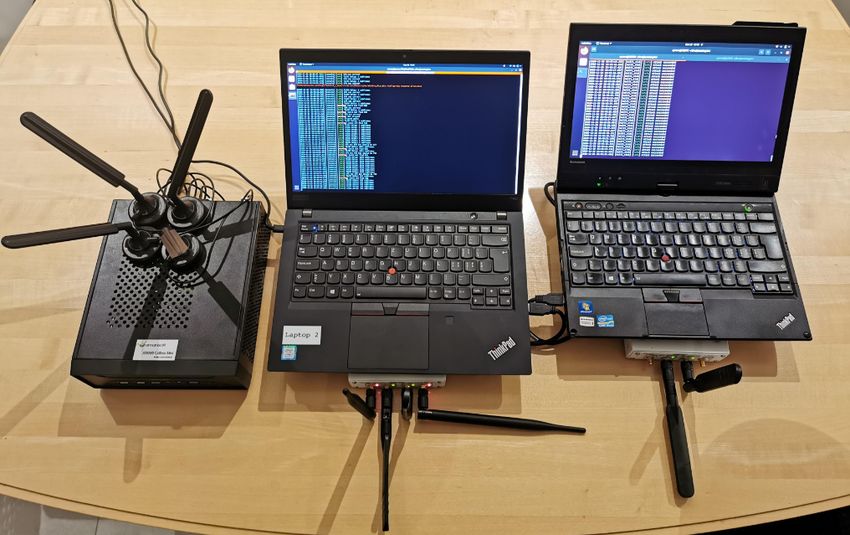
Figure 9: Experimental Setup
NAS Identity Response
To evaluate our attacks in a realistic setting, we set up a
Figure 8: IMSI Catcher built using an Uplink Sniffer and private LTE network in a shielded environment, using the
AdaptOver. After the attacker records a Service or Attach commercially available Amarisoft Callbox Mini as the base
Request that is sent by the victim UE, the attacker injects station and core network. To execute our attacks, we used
the NAS Identification Request message, causing the UE to a Lenovo T490 notebook, connected to an Ettus Research
disclose its IMSI in plaintext. USRP B210 software-defined radio. To aid with debugging,
we used a Lenovo X230T notebook to decode the downlink
using our implementation, srsUE from srsLTE [15] to act as a
IMSI catchers [8] enable an attacker to set up a fake base
UE, and finally installed QCSuper [13] on some of the phones
station, to which UEs connect and leak their IMSI (persistent
to validate the reception of the messages.
identifiers). Because of the design of LTE, preventing IMSI
catchers fully is not feasible. 5G addresses this attack vector,
however, downgrade attacks remain a major issue until LTE 5.2 Service Reject Attack Evaluation
is fully phased out.
Related work [10] shows that an IMSI catcher can be im- We carried out the service reject attack, described in section
plemented by combining AdaptOver with a custom made 3.1, in a shielded environment using our AdaptOver imple-
LTE uplink sniffer and defeat existing IMSI catcher detection mentation. To that end, we first connected the smartphones
techniques. This is because the detection of IMSI catchers to the network regularly and waited until they entered idle
mainly relies on recognizing the presence of fake base sta- mode. We then started the attack and interacted with the smart-
tions [3, 4, 11, 14, 16, 20]. We briefly summarize it below and phones, such that they may exit the idle mode and enter the
illustrate it in Figure 8. service request procedure, which we then attacked with our
AdaptOver attack, sending a Service Reject message.
In the attack, the adversary injects using AdaptOver an
Identity Request message after the base station sent the RRC
Connection Setup message. No matter if the UE has sent Results. Only the iPhone X reconnected by itself after
an Attach or Service Request message, as per the 3GPP TS nearly 10h. All other tested smartphones did not re-connect
24.301 [2], the UE will respond with its IMSI in plain text. within 12 hours. For most of the models, either toggling flight
This response is then captured by the uplink sniffer of the mode or restarting was enough to re-establish a connection.
attacker, as shown in [10]. For the LG Nexus 5X, it required the re-insertion of the SIM
9Service Reject Attach Reject Authentication Reject
Phone Duration1 Action2 GUI3 Duration1 Action2 GUI3 Duration1 Action2 GUI3
Pixel 2 >12h R > 12h R > 12h R
Pixel 3a >12h T > 12h T > 12h T
Huawei P20 Pro >12h T > 12h T > 12h T
Huawei P30 >12h T > 12h T >12h T
Huawei P30 Lite >12h T > 12h T > 12h T
Samsung Galaxy A8 >12h T > 12h T > 12h T
Samsung Galaxy S10 >12h T > 12h T > 12h T
LG Nexus 5X >12h S > 12h R > 12h R
iPhone 6S >12h R > 12h R > 12h R
iPhone 7 >12h T > 12h T > 12h T
iPhone 8 >12h T > 12h T > 12h T
iPhone 11 >12h T > 12h T > 12h T
iPhone 11 Pro >12h T > 12h T > 12h T
iPhone X 9.78h T > 12h T > 12h T
HTC U12+ >12h T > 12h T > 12h T
OnePlus 7T Pro >12h T > 12h T > 12h T
Xiaomi Mi 9 >12h T > 12h T > 12h T
Xiaomi Mi Mix 3 5G >12h T > 12h T > 12h T
1 Duration until the UE re-established a connection by itself
2 Action that will re-connect the phone immediately, T: Toggle flight mode, R: Restart phone, S: Reinsert SIM
Card
3 Whether an indicator on the GUI is present
Table 1: Attack Results for DoS Attack carried out by AdaptOver
card to restore connectivity. Furthermore, some of the smart- 5.4 Authentication Reject Attack Evaluation
phones displayed a message on the phone, indicating a prob-
To evaluate the effect of our Authentication Reject attack, we
lem with the SIM card. A selection of those messages is
implemented the attack in AdaptOver. We first put the UEs
shown in Figure 10, with similar messages shown on the
in flight mode, after which we started the attack, and then
Huawei P30, Samsung Galaxy S10, and LG Nexus 5X.
turned flight mode off for each UE, triggering an attachment
procedure and therefore our attack. After each phone was
subjected to the attack, the attacker was turned off and the
5.3 Attach Reject Attack Evaluation
phones left alone.
Using the design from section 3, we implemented the Attach
Reject attack using AdaptOver. We first put the UEs in flight Results. All tested phones did not re-connect within 12
mode, after which we started the attack, and then turned flight hours. Table 1 summarizes the results, including the remedial
mode off for each UE, triggering an attachment procedure and actions necessary. For the Huawei P30, it was necessary to
therefore our attack. After a few minutes, we turned off the send the Authentication Reject message twice for the attack to
attack. Using the logs from the Amarisoft Callbox Mini, we succeed, as it replied to the first Authentication Reject again
verified that there were no further connection attempts from with an Authentication Failure.
the UE since the first Attach Reject.
5.5 Power Requirements
Results. None of the phones tried to re-establish a connec- To evaluate the required power for an attack to work, we
tion to the network within 12 hours. In Table 1, the results are executed the attack in a shielded environment, with the at-
listed for each tested smartphone. tacker and the eNodeB both at exactly 1m distance from the
10PAttacker − PeNodeB − 3dB
!
dAttacker ≤ d↔ · 10 20 (1)
Due to regulations, testing this outside a shielded environ-
ment is not feasible. If we conservatively assume a transmit
(a) iPhone 6S power, including any antenna gains, of 40dBm for the eNodeB
and 20dBm for the attacker, we can get an idea of how large
the attack radius is, as shown in Table 3.
d↔ Downlink max dAttacker
100m 7.1m
(b) Samsung Galaxy A8 500m 35.4m
1km 70.8m
Figure 10: GUI indicators of smartphones subjected to the
Service Reject attack Table 3: Estimated Attack Range for an attacker transmit
power of 20dB. The basestation emits its downlink signal
with a power of 40dB. d↔ denotes distance between UE and
UE. Then, we changed the output gain of the attacker and basetation. max dAttacker is the distance between attacker and
measured how many overshadowed messages were decoded victim UE.
correctly from the attacker vs how many were from the legiti-
mate eNodeB. Messages that could not be decoded at all were
discarded. Then, we connected the output of both eNodeB and
attacker to a Keysight oscilloscope and measured the power 6 Countermeasures
difference in dB. Although we found that a relative power
advantage (J/S) of 1.8dB is sufficient to achieve a 100% attack In the following section, we’re discussing possible counter-
success rate, which is an improvement from [21], this could be measures to the presented AdaptOver DoS attacks and how
due to differences in the experimental setups. Table 2 shows to implement them.
the measurements of J/S and the corresponding success rate.
Both the standard-deviation (σJ/S ) and the mean (µJ/S ) are
listed. 6.1 Retry Mechanism
Guaranteeing availability in LTE is not possible, as the wire-
µJ/S σJ/S Success Rate less channel can always be sufficiently disturbed such that
-2.049 dB 0.627 0% communication is impossible. However, this requires a high
-1.1202 dB 0.675 1.325% output power and constant transmission of the attacker, while
-0.117 dB 0.665 30.625% our attacks induced a persistent denial-of-service with com-
0.639 dB 0.619 96.825% paratively low power. However, our attacks were only suc-
1.870 dB 0.641 100% cessful because the smartphones did not try to re-establish a
2.559 dB 0.733 100% connection, even after several hours.
Our recommendation to the baseband developers is thus
Table 2: Summary of Overshadowing Success Rate and Re- to retry establishing a connection more often, no matter the
sulting J/S cause of failure. This will force the attacker to attack its victim
continuously, requiring a larger time and resource investment.
Ideally, the cost and effectiveness of an attacker deploying
AdaptOver should be similar to a regular noise jamming at-
tack. The downside to this approach is that the retry requests
Resulting Attack Range. Based on the 3dB number, we of UEs that do not have a legitimate reason to connect to
can establish the maximum distance dAttacker of the attacker the network will increase the load on the core network with
to the UE in relation to the distance from the UE to the base their continued attempts. To balance these opposing needs,
station d↔ and the output power of the attacker PAttacker and we propose implementing the retry mechanism as an expo-
the base station PeNodeB . Assuming a free space path loss nential back-off, spacing retries to avoid congestion on the
model, we get: core network.
116.2 Detection these NAS authentication, attach, and service reject attacks
have been covered in [7, 8, 19], all using a fake base station.
Detecting the AdaptOver attacks on lower layers is not diffi-
cult, as we are continuously overshadowing the downlink with
identical information to blank out any legitimate downlink Downlink Overshadowing. Signal overshadowing in LTE
traffic, presenting a highly identifiable characteristic. On a has first been discussed by SigOver [21]. In SigOver, the
higher layer, separating a legitimate rejection from a bogus authors implemented a DoS attack using IMSI paging and
one could be possible by identifying the absence of a message SIB overshadowing. They further implement a signalling
authentication code. In [5], Echeverria et al. tried to identify storm, network downgrade and coarse-grained tracking at-
an attach, service or authentication reject attack originating tack against LTE. Our work significantly builds and improves
from a fake base station, but other than the presence of the upon their work, enabling interactive and adaptive attacks on
reject message, they could not identify any characteristic that higher layer procedures, which result in more persistent DoS
would clearly separate the attack from a legitimate rejection. attacks. This work has been used in [10] to create a highly
covert IMSI extractor, enabling persistent tracking over an
abritrarily long period of time.
6.3 Integrity Protection
When requiring integrity of messages between participants, a
message authentication code (MAC) is added to the message, 8 Conclusion
proving to the recipient that it has not been tampered with.
None of the messages we sent contained such a valid MAC, In this paper, we developed and implemented a new attack
as our attacker model excluded the attacker’s knowledge of method against LTE called AdaptOver. We implemented three
the shared key between UE and the operator. However, our DoS attack variants capable of denying LTE service of all
attacks succeeded nonetheless. The technical specification tested current smartphones across multiple base stations over
of 3GPP [2] requires that non-integrity protected messages more than 12 hours. We proposed simple and effective coun-
should not be accepted by the UE after it has established termeasures to the DoS attacks, which are implementable by
an authenticated session. Clearly, this was not implemented baseband vendors without any changes to the standard.
correctly, but can easily be corrected with the retry measure
proposed in section 6.1.
Acknowledgments
7 Related Work We thank the authors of SigOver for sharing their code.
Fake Base Station Attack Detection. Fake base station
attacks require a considerably larger power output as an References
overshadowing attack, as shown by SigOver [21]. Due to
[1] 3GPP. 3GPP TS 36.822, September 2012. Last accessed:
their high power output and the requirement to continuously
21.09.2020.
broadcast their configuration, fake base station attacks are
highly detectable, as has been explored by numerous works [2] 3GPP. 3GPP TS 24.301, July 2020. Last accessed: 21.09.2020.
[3, 4, 11, 14, 16, 20]. In these works, the authors detect fake [3] CellularPrivacy. CellularPrivacy/Android-IMSI-Catcher-
base stations due to their unusual broadcast configuration, Detector, December 2020. Last accessed: 07.12.2020.
location, or other indicators. In [5], the authors do not use
[4] Adrian Dabrowski, Nicola Pianta, Thomas Klepp, Martin Mu-
lower layer indicators to detect the presence of a fake base
lazzani, and Edgar Weippl. IMSI-catch me if you can: IMSI-
station, but rather rely on the protocol trace of the interaction catcher-catchers. In Proceedings of the 30th Annual Computer
with the fake base station. Security Applications Conference on - ACSAC ’14, pages 246–
255, New Orleans, Louisiana, 2014. ACM Press.
Fake Base Station Attack Impact. Despite their high de- [5] Mitziu Echeverria, Zeeshan Ahmed, Bincheng Wang, M. Fa-
tectability, fake base station attacks are of high impact and reed Arif, Syed Rafiul Hussain, and Omar Chowdhury.
have been shown to be useful for both DoS and MITM attacks. PHOENIX: Device-Centric Cellular Network Protocol Mon-
In [17, 18], the authors managed to manipulate regular user itoring using Runtime Verification. arXiv:2101.00328 [cs],
traffic, using a fake base station as a MITM. In [9], the au- January 2021. arXiv: 2101.00328.
thors investigated the implementation of multiple real-world [6] Gianluca Foddis, Rosario G. Garroppo, Stefano Giordano, Gre-
MMEs, uncovering many implementation defects of opera- gorio Procissi, Simone Roma, and Simone Topazzi. LTE traffic
tors leading to DoS and SMS phishing. In this paper, we have analysis for signalling load and energy consumption trade-off
focused on denial-of-service attacks enabled by the 3GPP in mobile networks. In 2015 IEEE International Conference
standard, and thus used NAS reject attacks. The principle of on Communications (ICC), pages 6005–6010, 2015.
12[7] Syed Rafiul Hussain, Omar Chowdhury, Shagufta Mehnaz, [21] Hojoon Yang, Sangwook Bae, Mincheol Son, Hongil Kim,
and Elisa Bertino. LTEInspector: A Systematic Approach for Song Min Kim, and Yongdae Kim. Hiding in plain signal:
Adversarial Testing of 4G LTE. In Proceedings 2018 Network physical signal overshadowing attack on LTE. In Proceed-
and Distributed System Security Symposium, San Diego, CA, ings of the 28th USENIX Conference on Security Symposium,
2018. Internet Society. Last accessed: 30.04.2020. SEC’19, pages 55–72, USA, August 2019. USENIX Associa-
[8] Roger Piqueras Jover. LTE security, protocol exploits and tion. Last accessed: 16.10.2020.
location tracking experimentation with low-cost software radio.
arXiv:1607.05171 [cs], July 2016. arXiv: 1607.05171, Last
accessed: 30.04.2020.
[9] Hongil Kim, Jiho Lee, Eunkyu Lee, and Yongdae Kim. Touch-
ing the Untouchables: Dynamic Security Analysis of the LTE
Control Plane. In 2019 IEEE Symposium on Security and
Privacy (SP), pages 1153–1168, May 2019.
[10] Martin Kotuliak, Simon Erni, Patrick Leu, Marc Röschlin, and
Srdjan Capkun. LTrack: Stealthy Tracking of Mobile Phones
in LTE. arXiv, June 2021.
[11] Zhenhua Li, Weiwei Wang, Christo Wilson, Jian Chen, Chen
Qian, Taeho Jung, Lan Zhang, Kebin Liu, Xiangyang Li, and
Yunhao Liu. FBS-Radar: Uncovering Fake Base Stations at
Scale in the Wild. January 2017.
[12] Marc Lichtman, Roger Piqueras Jover, Mina Labib, Raghunan-
dan Rao, Vuk Marojevic, and Jeffrey H. Reed. LTE/LTE-A
jamming, spoofing, and sniffing: threat assessment and miti-
gation. IEEE Communications Magazine, 54(4):54–61, April
2016. Conference Name: IEEE Communications Magazine.
[13] Marin Moulinier and Benoit Michau. P1sec/QCSuper, Novem-
ber 2020. Last accessed: 30.11.2020.
[14] Prajwol Kumar Nakarmi and Karl Norrman. Detecting false
base stations in mobile networks, June 2018. Last accessed:
07.12.2020.
[15] Andre Puschmann, Ismael Gomez, Pedro Alvarez, Xavier
Arteaga, Francisco Paisana, Paul Sutton, and Justin Tallon.
srsLTE/srsLTE, April 2020. Last accessed: 28.04.2020.
[16] Cooper Quintin. Detecting Fake 4G Base Stations in Real
Time. 2020. Published: DEF CON, Last accessed: 07.12.2020.
[17] David Rupprecht, Katharina Kohls, Thorsten Holz, and
Christina Popper. Breaking LTE on Layer Two. In 2019 IEEE
Symposium on Security and Privacy (SP), pages 1121–1136,
San Francisco, CA, USA, May 2019. IEEE. Last accessed:
30.04.2020.
[18] David Rupprecht, Katharina Kohls, Thorsten Holz, and
Christina Pöpper. IMP4GT: IMPersonation Attacks in 4G
NeTworks. In ISOC Network and Distributed System Security
Symposium (NDSS). ISOC, February 2020.
[19] Altaf Shaik, Ravishankar Borgaonkar, N. Asokan, Valtteri
Niemi, and Jean-Pierre Seifert. Practical Attacks Against
Privacy and Availability in 4G/LTE Mobile Communication
Systems. arXiv:1510.07563 [cs], August 2017. arXiv:
1510.07563, Last accessed: 30.04.2020.
[20] Thanh van Do, Hai Thanh Nguyen, Nikolov Momchil, and
Van Thuan Do. Detecting IMSI-Catcher Using Soft Computing.
In Michael W. Berry, Azlinah Mohamed, and Bee Wah Yap,
editors, Soft Computing in Data Science, volume 545, pages
129–140. Springer Singapore, Singapore, 2015. Series Title:
Communications in Computer and Information Science.
13You can also read