A novel neck brace to characterize neck mobility impairments following neck dissection in head and neck cancer patients
←
→
Page content transcription
If your browser does not render page correctly, please read the page content below
Wearable Technologies (2021), 2, e8
        doi:10.1017/wtc.2021.8

        RESEARCH ARTICLE

        A novel neck brace to characterize neck mobility impairments
        following neck dissection in head and neck cancer patients
        Biing-Chwen Chang1 , Haohan Zhang1, Sallie Long2, Adetokunbo Obayemi2,
        Scott H. Troob2,3,4 and Sunil K. Agrawal1,5*
        1
         Department of Mechanical Engineering, School of Engineering and Applied Sciences, Columbia University, New York,
        New York, USA
        2
         Department of Otolaryngology—Head and Neck Surgery, Columbia University Irving Medical Center, New York, New York, USA
        3
         College of Physicians and Surgeons, Columbia University, New York, New York, USA
        4
         New York Presbyterian-Columbia University Irving Medical Center, New York, New York, USA
        5
         Department of Rehabilitative and Regenerative Medicine, College of Physicians and Surgeons, Columbia University, New York,
        New York, USA
        *Corresponding author: Email: sunil.agrawal@columbia.edu
        Received: 13 November 2020; Revised: 11 May 2021; Accepted: 01 June 2021
        Key words: neck dissection; range of motion measurements; wearable neck brace

        Abstract
        Objective: This article introduces a dynamic neck brace to measure the full range of motion (RoM) of the head–neck.
        This easy-to-wear brace was used, along with surface electromyography (EMG), to study changes in movement
        characteristics after neck dissection (ND) in a clinical setting.
        Methods: The brace was inspired by the head–neck anatomy and was designed based on the head–neck movement of
        10 healthy individuals. A 6 degrees-of-freedom open-chain structure was adopted to allow full RoM of the head–neck
        with respect to the shoulders. The physical model was realized by 3D printed materials and inexpensive sensors. Five
        subjects, who underwent unilateral selective ND, were assessed preoperative and postoperative using this prototype
        during the head–neck motions. Concurrent EMG measurements of their sternocleidomastoid, splenius capitis, and
        trapezius muscles were made.
        Results: Reduced RoM during lateral bending on both sides of the neck was observed after surgery, with a mean angle
        change of 8.03° on the dissected side (95% confidence intervals [CI], 3.11–12.94) and 9.29° on the nondissected side
        (95% CI, 4.88–13.69), where CI denotes the confidence interval. Axial rotation showed a reduction in the RoM by
        5.37° (95% CI, 2.34–8.39) on the nondissection side. Neck extension showed a slight increase in the RoM by 3.15°
        (95% CI, 0.81–5.49) postoperatively.
        Conclusions: This brace may serve as a simple but useful tool in the clinic to document head–neck RoM changes in
        patients undergoing ND. Such a characterization may help clinicians evaluate the surgical procedure and guide the
        recovery of patients.

        Introduction
        Head and neck cancers encompass a wide variety of cutaneous, salivary, and mucosal malignancies.
        These cancers often spread to the regional lymphatics of the neck, that is, the cervical lymph nodes (Shah
        et al., 2001). Neck dissection (ND) is a surgical method for removing cervical lymph nodes, suspected to

        © The Author(s), 2021. Published by Cambridge University Press. This is an Open Access article, distributed under the terms of the Creative Commons
        Attribution licence (http://creativecommons.org/licenses/by/4.0/), which permits unrestricted re-use, distribution, and reproduction in any medium,
        provided the original work is properly cited.

Downloaded from https://www.cambridge.org/core. 21 Jul 2021 at 17:57:26, subject to the Cambridge Core terms of use.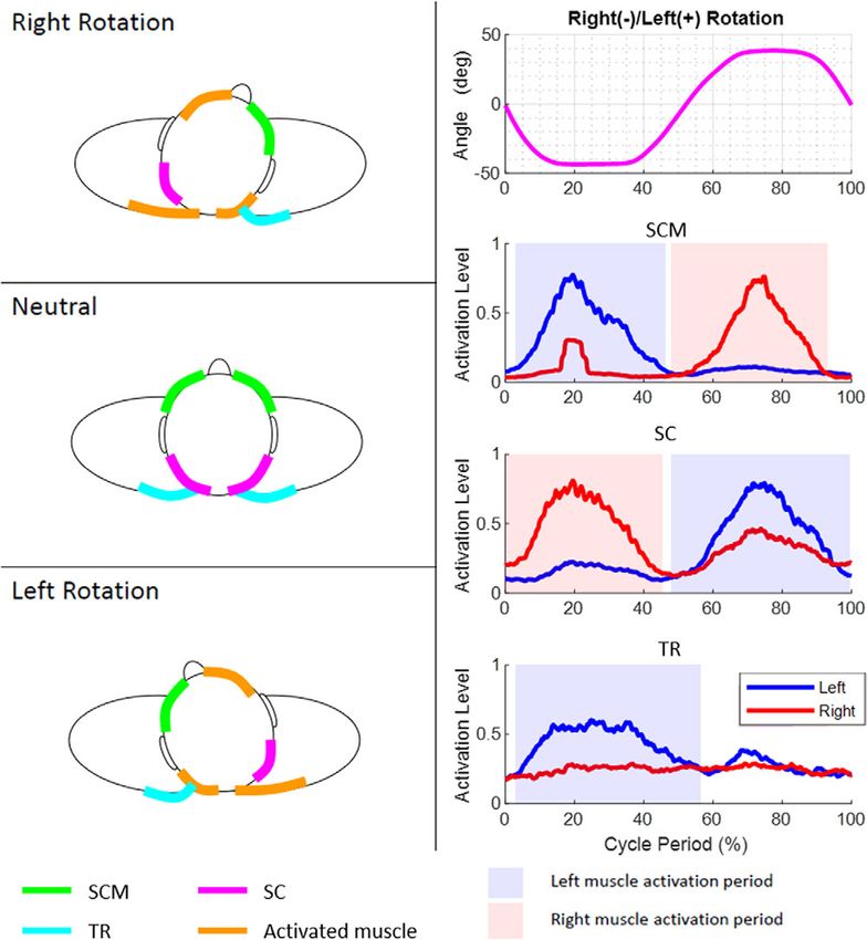
e8-2         Biing-Chwen Chang et al.

        contain deposits of cancer. ND requires manipulation of the 11th cranial nerve, that is, the spinal accessory
        nerve, which runs in an oblique line from the skull base to the back, innervating the neck sternocleido-
        mastoid (SCM) and trapezius (TR) muscles. Injury to the 11th cranial nerve, may unfortunately, cause
        substantial morbidity post-surgery.
           Cutaneous and mucosal cancers of the head and neck are the first and the sixth most common forms of
        cancer in the United States. These affect 5.4 million nonmelanoma skin cancer patients, 87,000 melanoma
        skin cancer patients, and 65,000 head and neck cancer patients per year (Howlader et al., 2017b).
        Denervation injury to the spinal accessory nerve occurs during ND (Dijkstra et al., 2001). Lack of
        innervation to the SCM and TR muscles results in pain and restricted range of motion (RoM) in the
        shoulders and neck, and significantly impacts patients’ quality of life (Eickmeyer et al., 2014). The
        confirmation of denervation is made by electromyography (EMG). During ND, manipulation of the
        spinal accessory nerve is required and this manipulation may result in transient or permanent injury to
        the spinal accessory nerve and muscle denervation of the SCM and TR muscles (Dijkstra et al., 2001).
        The lack of innervation of the SCM and TR muscles results in restricted RoM of the shoulder and neck
        and significantly impacts patients’ quality of life even years after the treatment (Erisen et al., 2004;
        Eickmeyer et al., 2014).
           ND associated movement disorder is a clinical diagnosis. Exercise-based physiotherapy is often
        prescribed for the affected muscles as well as accessory muscles of the neck and shoulder girdle.
        Historically, the degree of movement restriction is measured by crude semi-quantitative assessment
        scales (Shah et al., 2001), protractors and goniometers (Erisen et al., 2004; Teymoortash et al., 2010),
        or a helmet with two inclinometers and a compass (Wilgen et al., 2004). Though patients perceive a
        benefit from therapy (Gallagher et al., 2015), there are currently few objective ways to guide the
        specific rehabilitative exercises or the duration of therapy (Lauchlan et al., 2008). Motion capture
        system and inertial measurement unit (IMU) are being used today as an angle measurement tool.
        Motion capture systems have high accuracy but require more time and ample space to set up and are
        less suitable to be used during patients’ routine clinical visits. IMUs are portable but usually suffer
        from the issue of signal drift due to the need to integrate velocity information to obtain position and
        orientation (Ahmad et al., 2013). Hence, a more reliable and portable measurement tool is needed for
        clinical assessment.
           Inspired by the dynamic neck brace for the amyotrophic lateral sclerosis (ALS) patients (Zhang et al.,
        2019), we postulated that a neck brace could help clinicians observe the extent of the impairment and
        recovery trends over a period of time after surgery or during the follow-up physical therapy. The brace that
        was proposed for ALS patients uses a parallel mechanism and has 3 degrees-of-freedom (3-DOF) (Zhang
        and Agrawal, 2017). It allows only 70% of range of rotation of the head–neck. Thus, it cannot be used
        to measure the full RoM of the head–neck which may be critical for evaluating the changes in
        movement characteristics in patients undergoing ND procedures. The CarNeck is a hybrid cable-
        driven system that allows 3-DOF with full RoM (Shoaib et al., 2019). However, the 3-DOF design still
        interferes with the 6-DOF motion of the head. Another study proposed a 6-DOF parallel mechanism
        but is too bulky to transport between clinics (Wu et al., 2016). Hence, the objective of this article is to
        develop a wearable neck brace with 6-DOF that can characterize the full RoM of the head–neck.
        Furthermore, we propose a procedure that pairs the measurement of head–neck motion with mea-
        surement of neck muscle activity using surface EMG to characterize the head–neck movements of
        patients at the musculoskeletal level.
           In the pilot study, this neck brace was used on five patients who underwent unilateral ND for cutaneous,
        oral cavity, or oropharyngeal squamous cell carcinoma. The neck kinematics and muscle EMGs during
        single-plane motions (sagittal plane flexion–extension, frontal plane lateral bending, and transverse plane
        axial rotation) were measured both before the surgery and 1 month postoperatively. These data show that
        this dynamic brace was capable of capturing the changes in movement characteristics of these subjects
        during their routine clinical visits with the surgeon.

Downloaded from https://www.cambridge.org/core. 21 Jul 2021 at 17:57:26, subject to the Cambridge Core terms of use.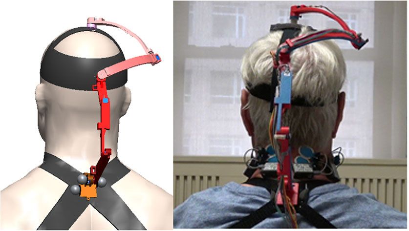
Wearable Technologies   e8-3

        Methods
        Head–Neck Brace Design
        Previous studies show that both translation and orientation are involved in natural head–neck motion
        (Zhang and Agrawal, 2017). According to studies of the normal kinematics of cervical spine, a major
        contributor to the motion of the head is the atlanto-axial joint (i.e., the joint between the first and second
        vertebrae C1–C2, see Figure 1), along with limited motions of the other joints in the upper cervical spine
        (Lind et al., 1989; Bogduk and Mercer, 2000). Also, the flexion–extension of the head is contributed by
        the entire cervical vertebral column. In a previous study, the fabricated robotic neck brace allows users to
        rotate the head in all three axes coupled with small translations (Zhang and Agrawal, 2017). This parallel
        mechanism design of the neck brace has the advantages of high stiffness and low inertia, but occupies
        more space around the head due to its specific parallel linkage structure.
            In the current design proposed in this article, the features of “light-weight” and “easy-to-use” are
        important design goals. We chose the structure of this neck brace as a six revolute-jointed serial chain
        mechanism. As shown in Figure 2, the structure is inspired by the anatomy (Figure 1) and the
        biomechanics of the neck motion (Lind et al., 1989; Bogduk and Mercer, 2000). The top cervical
        vertebrae (C1–C2) perform most of the head orientation, while the lower cervical vertebrae facilitate
        flexion–extension and lateral bending of the neck to change the Euclidean distance between C1 and C7.
        Hence, the motion can be decoupled into rotation at C1–C2 and translation from C2 to C7. In the design of
        the wearable robot, the displacement of the end-effector (P) is contributed by the three proximal joints
        J1,.., J3 and rotation from the three distal joints J4,.., J6. The lower cervical spine (C4–C7) provides the
        RoM for flexion–extension motion of the head–neck. Hence, the rotation axes of joints J1 and J2 were
        chosen parallel to the axis of flexion–extension of the head–neck in the design. To allow for lateral
        bending during flexion–extension, the axes of J3 and J4 are chosen perpendicular to J1 and J2. The axial
        rotation occurs mainly at the atlanto-axial joint with coupled motion in the other two planes. Therefore, we
        choose the axes of J4, J5, and J6 to intersect at a point C which anatomically aligns with the center of
        atlanto-axial joint to mimic a ball joint. Since the axial rotation of the head–neck is roughly around an axis

          Figure 1. The anatomy and muscle location of the neck. (Left) A side view of the cervical vertebrae.
         (Middle and Right) The back view and side view of the muscle locations. Blue dots are the electromy-
                                       ography (EMG) electrode placements.
Downloaded from https://www.cambridge.org/core. 21 Jul 2021 at 17:57:26, subject to the Cambridge Core terms of use.
e8-4             Biing-Chwen Chang et al.

        Figure 2. Schematic of the six revolute joint manipulator. The base joint is labeled J1 and the following
        joints are labeled J2, J3, J4, J5, and J6, respectively, in the sequence. The joint axes of the last three joints
                            intersect at a point labeled C and the end-effector is labeled as P.

                                            Table 1. D–H parameters of the six revolute joint manipulator

             Link                       θi (rad)                         di (cm)                         αi (rad)      ai (cm)

             1                             θ1a                             0                                0           15
             2                             θ2a                             0                               π/2          10
             3                             θ3a                              16                              0            5
             4                             θ4a                             0                               π/3           0
             5                             θ5a                             0                               π/3           0
             6                             θ6a                             17                               0           1.5
        a
            Input variables.

        that is geometrically along the cervical spine, J6 is placed distally along the head to align its joint axis
        along the cervical spine. The motion of the end-effector is governed by the Denavit–Hartenberg (D–H)
        model parameters such as the link lengths and joint offsets, as presented in Table 1.
            The design goal of this device is to measure the full RoM of the head. During the design phase, the
        motion data of the head–neck over the full rotational range were recorded from 10 healthy individuals
        (26.8[4.26] years, range 24–29), using an eight-camera motion capture system (Vicon, Oxford, UK) with
        a sampling rate of 200 Hz. Eight retro-reflective markers were placed on the human body to form two rigid
        bodies. Four markers were placed on the trunk. One of these four markers was placed approximately on
        the cervical vertebrae (C7), where the base would be mounted. Other three markers were placed at front
        chest, and right and left acromion. A headband with four markers was placed on the head. One marker was
        placed approximately at the top of the atlas joint (C1). When designing the physical model, this marker
        helped locate the head’s position so that the linkage structure avoids colliding with the head. Another
        marker was placed on the top of the head, representing the end-effector position. Other two markers were
        at the left and right of the head. A static trial and four dynamic trials were recorded in this experiment. In
        the static trial, the upright neutral configuration of the subject was recorded. This posture was then used to
        construct a reference coordinate frame to describe the ensuing dynamic motions. In the dynamic trials, the
        subject was instructed to perform rotations within each of the three anatomical planes, followed by a
        spatial rolling movement of the head–neck that involved motions in all three planes. Each motion was
        repeated five times at self-selected speeds by the subject.

Downloaded from https://www.cambridge.org/core. 21 Jul 2021 at 17:57:26, subject to the Cambridge Core terms of use.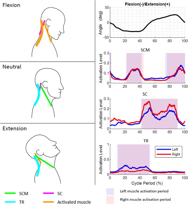
Wearable Technologies   e8-5

          Figure 3. End-effector workspace from 10 subjects. The red space is the workspace created from the
           marker at the top of the head which the end-effector should reach. The blue space is created from
             the marker at C1, which the device should prevent from hitting. The black dot is the common
              rotation center of the red space. The point clouds are in the trunk coordinate for which the
                                               marker on C7 is the origin.

            The data recorded from the subjects are visually displayed in Figure 3. The blue workspace shows the
        marker position C1 while the red workspace is for the reference point on the head. Since most of the head
        orientation happens at C1–C2, we assumed that the point cloud in the red workspace has a rotation center.
        A geometric approach was used to fit a sphere within the point cloud along with a center and a radius.
        These results helped us design the arc of linkages that connect the top three distal joints. We then chose the
        D–H model parameters of the neck brace through an exhaustive search so that the end-effector could reach
        all points within the workspace. To avoid the intermediate joints from hitting the head, the location of J4
        was examined. A plane including the three markers at C1 and the shoulders was used to divide the
        workspace into a region for the head and for C1. J4 was chosen to be in region for C1. Additionally, the
        operation ranges of joint angles were defined such that they do not interfere with the head and neck during
        the dynamic movements.
            The computer-aided design model and the actual device are shown in Figure 4. The base of the brace is
        on C7 and attaches to the human body through a pair of bands at the shoulders. A small bubble level is
        mounted on the base of the device to help position it relative to the shoulders. The end-effecter is attached
        to the top of the head with a soft elastic band. The linkages were 3D printed. The total weight of the brace,
        including the electronics, is 200 g which is about 1/25 of the weight of the human head. Each joint has a
        potentiometer along its rotational axis.
            To address model mismatch between the theory and constructed brace in the presence of manufactur-
        ing and assembly tolerances, we took data from two subjects with the motion capture system when
        they performed head movements with the brace attached. Inverse kinematics was performed with the
        theoretical robot model given data from motion capture to find joint angles and simultaneously the
        potentiometer voltages were recorded at each joint. The potentiometer voltages were then polynomial
        fitted to the joint angles using the fit function in MATLAB to minimize errors between the head
        position/orientation computed by using the forward kinematics and the camera data. Once the model
        fitting was done, we validate the model with data from two additional subjects who were asked to do
        similar experiment as those by subjects for model matching experiment. The accuracy of the brace

Downloaded from https://www.cambridge.org/core. 21 Jul 2021 at 17:57:26, subject to the Cambridge Core terms of use.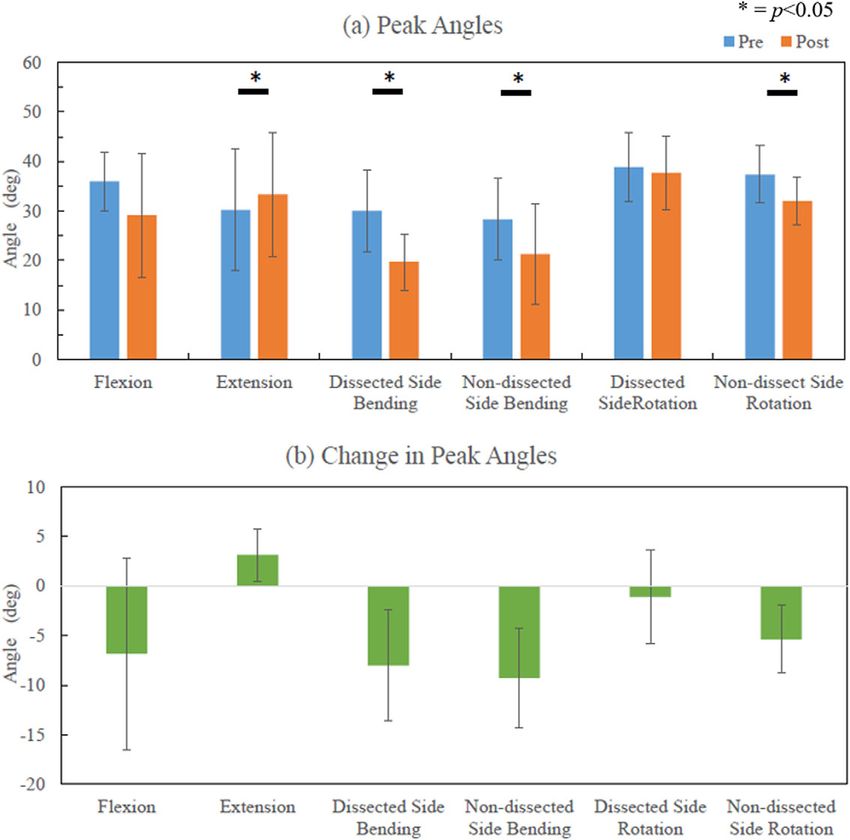
e8-6         Biing-Chwen Chang et al.

        Figure 4. Schematic of the measurement brace and a picture of a subject using the brace. (Left) A CAD
           drawing of the measurement neck brace that consists of a series-chain with 6 degrees-of-freedom,
        designed for patients undergoing neck dissection for head and neck cancer. The base of the brace attaches
        to a rigid support worn by the user roughly around C7 vertebral segment. The end-effector of the series-
           chain attaches to a wearable cap. (Right) A participant wearing the brace during experimentation
           while sitting comfortably on a chair. Surface electrodes are mounted in the head and neck area to
               record muscle activity from bilateral sternocleidomastoid (SCM), splenius capitis (SC), and
                                                  trapezius (TR) muscles.

        model was tested against the motion capture system. The performance in three single-plane motions
        from a representative subject is presented in Figure 5, and the group data is shown in Table 2. Maximum
        angle error was obtained from the maximum angle difference between the motion capture system and
        the brace for the group. Root mean square (RMS) error was computed with the mean RMS error over
        trials and over subjects. The maximum angle errors are below 6° and the RMS errors are below 5° in
        single-plane motion.

        Experiments with Cancer Patients
        Five patients, without prior surgery or radiation, who underwent unilateral selective ND for cutaneous,
        oral cavity, or oropharyngeal squamous cell carcinoma were evaluated preoperatively and 4 weeks
        postoperatively. Four weeks was chosen as the optimal time point when denervation injury would be
        evident, while the impact of postoperative swelling or incisional pain would be minimal. Also, this time
        point allowed for measurement prior to the initiation of any potential radiation therapy to avoid any
        confounding results. The mean(SD) age was 59(7.25) years (range 51–68 years). Clinical data regarding
        primary tumor type, extent of ND and postoperative data are summarized in Table 3. Selective lympha-
        denectomy was performed by the same surgeon on the deep jugular chain lymph nodes contained within
        selective regions I–V (as indicated by the primary tumor), which surround the spinal accessory nerve. In
        each case, the fascia connecting the spinal accessory nerve to the adjacent lymphatic and fibro-fatty tissue
        was atraumatically released and the nerve gently skeletonized and mobilized. There were no cases where
        the nerve was transected.
           The EMG electrodes were placed at six neck muscle sites, the SCM, the splenius capitis (SC), and the
        TR on both sides of the neck. The neck brace was then attached to the participant while they were asked
        to sit in an upright position on a chair. This determined the neutral configurations of the brace. The
        EMG signals were recorded wirelessly using TeleMyo DTS (Noraxon, AZ, USA). A microcontroller
        (NI myRIO-1900) was used to send a digital trigger between the neck brace and the EMG system for
Downloaded from https://www.cambridge.org/core. 21 Jul 2021 at 17:57:26, subject to the Cambridge Core terms of use.
Wearable Technologies                 e8-7

          Figure 5. The comparison between motion capture system (blue line) and the brace (red line) from a
         representative subject performing three single-plane head orientations. Only primary head rotation is
                                        shown for each single-plane movement.

                                                       Table 2. Angular errors from validation data

           Angle error (°)               Flexion–extension                   Lateral bending             Axial rotation              Rolling

           Maximum                                  5.73                                5.90                     5.44                      8.17
           RMS(SD)                            4.10(0.97)                          3.93(1.87)               4.06(0.77)                6.91(1.84)

        Abbreviations: RMS, root mean square; SD, standard deviation.

                                          Table 3. Subject characteristics who participated in the experiment

                                      Mean(SD)           Range              S1                 S2         S3               S4            S5

           Age (years)                59 (7.25)         51–68               54               65           57                68          51
           Height (cm)               177.8 (9.26)     150–177.8            188              185          165               173          178
           Weight (kg)               86.4 (9.61)       54.4–80              98               91           75                78           90
           Dissected side                 –               –               Right            Right         Left             Right        Right
           Neck levels                    –               –                1–4              2–4      Parotid, 2–4          1–4          1–4
             dissected
           Tumor primary                                                Oral cavity     Oropharynx    Cutaneous        Oral cavity   Oral cavity
           Pathology                                                       SCC             SCC          SCC               SCC           SCC
           Adjuvant treatment                                               RT             CRT          CRT                 –             –
           Subjective shoulder                                              No              No           Yes               No            No
             dysfunction

        Abbreviations: CRT, chemoradiation; RT, radiotherapy; SCC, squamous cell carcinoma.

Downloaded from https://www.cambridge.org/core. 21 Jul 2021 at 17:57:26, subject to the Cambridge Core terms of use.
e8-8         Biing-Chwen Chang et al.

        synchronization. These data were recorded and saved in the microcontroller with an interface on a laptop
        to visualize the data.
           All participants sat comfortably on a chair during the measurements. The participants were first asked
        to keep their head in an upright neutral position, followed by three single-plane motion cycles with their
        head and neck—axial rotation in the transverse plane, lateral bending in the coronal plane, and flexion/
        extension in the sagittal plane. Each cycle started from the neutral position and ended at the neutral
        position. Each cycle had three sub-blocks: (a) Movement from the neutral to one extreme, (b) Movement
        from the first extreme to the second extreme, and (c) Movement from the second extreme to the neutral.
        The subjects performed each single-plane motion five times continuously at self-selected speeds.
        The experiment was done during the scheduled clinical visits of the subjects and it took about 30 min
        to complete the experiment.
           The neck brace was sampled at 100 Hz and the EMG system was sampled at 1.5 kHz. The joint angles
        were low-pass filtered (zero lag fourth order Butterworth) at 6 Hz to reduce noise. The processing of the
        EMG signal from each channel was followed by: (a) filter the noise from cardiac beating using EMG
        software myoRESEARCH 3.10 (Noraxon, AZ, USA), (b) remove the DC offsets by subtracting the mean
        of each signal, (c) band-pass filter the data between 60 and 200 Hz, (d) full-wave rectify the signals,
        (e) create an envelope using moving averages with a window size of 300 data points (0.2 s), and (f)
        normalize the signal of each channel by the largest value recorded in that channel during all measurements
        of each participant in each visit. The continuous motion of each subject during a trial was segmented into
        five movement cycles. These cycles were averaged to compute the outcome variables. The cycles were
        segmented based on the primary angle of the motion, for example, flexion–extension during sagittal
        plane. They were then normalized with respect to time.
           Data analysis was performed using MATLAB (The MathWorks Inc., Natick, MA, USA). Confidence
        intervals (95% confidence intervals [CI]) and paired t test was used to compare the mean values before
        surgery and 1 month postoperatively. The outcome variables include the completion time of each cycle,
        the changes in RoM in three anatomical planes, the maximum/minimum head angles in those planes, and
        the timing of the EMG peaks of each neck muscle before and 1-month after the surgical procedure of each
        subject. The statistical significance was set at p < .05.

        Results
        In order to intuitively understand the single-plane motions of the head and neck, one can visualize the head
        as being connected to the shoulders by six ropes. The attachment points of these six ropes on the head and
        the shoulders are determined from the anatomical attachment points of the SCM, SC, and TR muscles in
        the human head and neck. A subset of these six ropes actuate, in coordination, to achieve the single-plane
        axial rotation, lateral bending, and flexion–extension of the head and neck.
            The axial rotation of the head and neck can be visualized as being actuated by a contralateral pair of
        ropes among SCM and SC and the ipsilateral TR paired with SCM. For example, right axial rotation is
        achieved by actuation of the left SCM, right SC, and left TR in the rotation cycle. The lateral bending of
        the head and neck is caused by the three ipsilateral ropes attached between the shoulders and the head. For
        example, the simultaneous actuation of the left SCM, left SC, and left TR results in left lateral bending.
        The flexion is caused by the pair of SCM while the TR holds the head to ensure a certain level of stiffness
        during the motion. Similarly, the extension is caused by the pair of SC. The patterns of these EMGs in
        relation to the motion peaks for a representative subject before the surgery and the instances within the
        movement cycle when a particular muscle turns on or off are provided in Figures 6–8.
            The group mean time period to complete a cycle was 3.41(0.82) s before surgery and 3.68(1.11) s
        postoperatively during axial rotation; 4.00(1.00) s before surgery and 3.93(1.04) s postoperatively during
        lateral bending; and 3.89(1.42) s before surgery and 3.44(0.99) s postoperatively during flexion/exten-
        sion. No statistically significances were found in all motions.
            Figure 9 shows the peak angles for the group during single-plane motions and changes in the peak
        angles for the group before and after surgery. Except for the extension motion, the peak angles in all other
Downloaded from https://www.cambridge.org/core. 21 Jul 2021 at 17:57:26, subject to the Cambridge Core terms of use.
Wearable Technologies   e8-9

            Figure 6. Motion, electromyography (EMG) patterns, and rope activations during axial rotation
             movement cycle. The axial rotation of the head and neck can be visualized as being caused by
                 a contralateral pair of ropes among sternocleidomastoid (SCM) and splenius capitis
                                   (SC) and the ipsilateral trapezius (TR) with SCM.

        motions decreased after surgery. Lateral bending on both sides showed a significant decrease by 8.03° on
        dissected side (95% CI, 3.11–12.94, p = .016) and 9.29° on the nondissected side (95% CI, 4.88–13.69,
        p = .007). Differences were also observed during axial rotation with the mean decrease of 5.37° (95% CI,
        2.34–8.39, p = .017) on the contralateral side of ND and during extension with a slight increase of 3.15°
        (95% CI, 0.81–5.49, p = .028).
           Figure 10 shows the relative timing of the muscle EMG peaks and motion peaks before and 1-month post-
        surgery. The plots show that the location of EMG peaks had large variation in all motions after surgery
        among the subjects. However, comparing the peak timing before and after the surgery, significant differences
        were found in SC on the dissected side during flexion–extension with timing 9% earlier (95% CI, 3–16,
        p = .024) and lateral bending with timing 12% earlier (95% CI, 2–22, p = .037). SC on the nondissected side
        during axial rotation, the timing of the peak was 2% later (95% CI, 0–3, p = .042). The timing of maximum
        extension angle happened 5% earlier and showed a significant difference (95% CI, 1–10, p = .037).
Downloaded from https://www.cambridge.org/core. 21 Jul 2021 at 17:57:26, subject to the Cambridge Core terms of use.
e8-10 Biing-Chwen Chang et al.
Figure 7. Motion, electromyography (EMG) patterns, and rope activations during bending
movement cycle. The lateral bending of the head and neck is caused by three ipsilateral
ropes attached between the shoulders and the head.
Discussion
In this study, we designed a 6-DOF serial chain neck brace as a measurement tool for the RoM of the head–
neck in patients who undergo head–neck surgery. The architecture of the neck brace was selected by
understanding the biomechanics during the motion of the head–neck. We observed the neck motion from
10 healthy subjects using a motion capture system and used their data to select and optimize the physical
structure of the neck brace. The D–H parameters of the design were chosen so that we could measure full
RoM of the head–neck. We optimized the coefficients of the brace model to obtain the characteristic of the
device. We validated the performance of the device with two subjects and showed that the RMS errors
were within 5°. The device was then used to measure the RoM changes before and after the ND of
five patients during their regular clinical visits. The results showed that the brace captured a significant
Downloaded from https://www.cambridge.org/core. 21 Jul 2021 at 17:57:26, subject to the Cambridge Core terms of use.Wearable Technologies e8-11
Figure 8. Motion, electromyography (EMG) patterns, and rope activations during flexion–extension
movement cycle. The flexion is caused by the two sternocleidomastoid (SCM) while the trapezius
(TR) provides stiffness during the motion.
decrease in lateral bending after the surgery. Integrated with the EMG system, we also found that SC
muscles activated earlier during the single-plane motions postoperatively.
There are several advantages of using this device as a clinical measurement tool. It is a simple device to
use and is wearable by attaching its base to the end of the cervical vertebrae and the end-effector to the top
of the head. This can be easily done by an attending clinician. Additionally, this device fits subjects of
different body types. Furthermore, using low-cost potentiometers to measure the head angles provides
reliable measurement, which may not be achieved by an expensive IMU due to the signal drift over long
periods of time. We also have shown in this study that this tool can be easily paired with surface EMG
measurement to study the neck movement on the muscular level.
Comprehensive rehabilitation of head and neck cancer patients following ND is a major unmet need
(McEwen et al., 2016). Mucosal cancers of the head and neck are the sixth most common forms of cancer
Downloaded from https://www.cambridge.org/core. 21 Jul 2021 at 17:57:26, subject to the Cambridge Core terms of use.e8-12 Biing-Chwen Chang et al.
Figure 9. Group data on the peak angles and changes postoperatively. (a) Illustrates peak angles
preoperative and postoperative. (b) The change in peak angles.
in the United States affecting approximately 65,000 patients per year (Howlader et al., 2017a). Rising
rates of skin cancers and human papilloma virus associated cancers of the tonsil and tongue are resulting in
a large population of patients living with treatment-related morbidity considering the need for cervical
lymphadenectomy along with primary resection. Early age at presentation and high cure rates of such
cancers translate to more patient-years of life lived with decreased quality of life after surgical therapy. When
questioned, patients have consistently identified “guided exercise” and “physical therapy” as two unmet
needs (McEwen et al., 2016). While ND offers increased diagnostic and therapeutic advantage, it is not
uncommon for there to be iatrogenic injuries to vital neurovascular structures, including the accessory nerve
(Köybasioglu et al., 2000). These have also been identified by patients as needs most frequently overlooked
by physicians, in particular with the need for increased psychosocial support. An easy-to-use, precise, and
reproducible screening tool is needed to identify patients who suffer from ND associated movement
disorders. Such a tool can be used to identify patients who are in need for targeted interventions, to develop
evidence based rehabilitative programs, and to measure accurately the response of treatments.
Downloaded from https://www.cambridge.org/core. 21 Jul 2021 at 17:57:26, subject to the Cambridge Core terms of use.Wearable Technologies e8-13
Denervation injury and associated movement disorders are often not apparent until the patients have
left the hospital. This delay in presentation leads to under detection of ND related movement disorders as
patients fail to fully report these symptoms and physicians overlook these issues given the time constraints
of outpatient cancer visits. The development of a screening tool can help identify patients suffering from
decreased quality-of-life and those who should be targeted for physical therapy interventions.
Most studies have focused on movement disorders of the shoulders but investigations of movement
disorders in the neck are currently lacking. Movement restrictions and compensatory patterns of neck
muscles have not been fully described. Previous studies have compared the dysfunction and quality of life
differences between nerve-sacrificing and nerve-sparing ND. Leipzig et al. (1983) reported that patients
had less dysfunction with nerve preserving selective lymphadenectomy compared to those who under-
went nerve-sacrificing radical ND. Cheng et al. (2000) showed patients with selective ND had less nerve
damage and therefore less shoulder disability. Eickmeyer et al. (2014) demonstrated that patients who had
nerve-sacrificing ND reported poorer quality of life score and poorer shoulder functioning after 5 years.
In the group data, the peak flexion angle, lateral bending on both sides, and nondissection side rotation
decreased (Figure 9). The rotation on the nondissected side is controlled by SCM and TR on the dissected
side and thus appeared diminished postoperatively. The mechanical stiffness of the brace may influence
the stiffness of the head and neck, however, this influence is there both before and after surgery. After
surgery, subjects tended to have their own strategy to perform the movement, which was captured in the
variability of the timing of the peak muscle activations after the surgery (Figure 10). However, significant
Figure 10. Peak muscle activations during a movement cycle for the group of subjects. (a) Preoperative
and (b) 1-month postoperative. Bars represent the temporal spread of the peak activations, circles
are median value, and “+” are outliers.
Downloaded from https://www.cambridge.org/core. 21 Jul 2021 at 17:57:26, subject to the Cambridge Core terms of use.e8-14 Biing-Chwen Chang et al.
differences were found in the peak timing of SC on the dissected side during lateral bending and flexion/
extension, which may relate to the significant differences found in RoMs. Thus, the peak timing on SC
could influence maximum RoM of the neck. Since we have small sample size and different people may
have distinct strategies, we did not find the correlation between the RoM and EMG.
One of the limitations of this device is that the errors progressively add due to the serial chain structure
of the mechanism. However, a 5° error is acceptable when the user is performing a large head orientation,
in excess of 100°. Motion capture systems require a long set up time in the clinic, which make these
impractical during routine visits. This study shows that the brace can be used to measure relative angle
changes before and after the surgery. The accuracy and repeatability of the angle measurements can be
further improved in the future.
Conclusions
In this study, we presented a neck brace based on a serial mechanism. The goal was to design a low-cost,
wearable, and easy-to-use device to measure the full range of motion of the head–neck. The brace was
designed with head–neck movement data from 10 healthy young subjects to determine the physical structure
of this device. The system was then used to study preoperative and postoperative ND performance.
The study suggests that restricted range of neck mobility occurs in patients after ND, even in the era
of selective lymphadenectomy and nerve-sparing procedures. The portability, accuracy, and ease with
which the data were collected suggest that the neck brace may serve as surgical procedure evaluation
tool in a head and neck surgery or rehabilitative medicine practice. The first is as a screening tool that
can accurately detect the presence of mobility restriction in patients undergoing surgery. The second is a
method of identifying the muscle group most in need of therapeutic intervention. Finally, the brace
can be used as a method of objectively quantifying the return of mobility as patients’ progress through
postoperative physical therapy.
Acknowledgments. We are grateful to the referees for their suggestions.
Funding Statement. We gratefully acknowledge partial support of the authors from the following grants and contracts: NSF
IIS-1527087, New York State Grants C31290GG and C32238GG.
Competing Interests. The authors declare no competing interests exist.
Authorship Contributions. B.-C.C., H.Z., S.H.T., and S.K.A. conceived and designed the study and wrote the article. B.-C.C.,
H.Z., S.L., and A.O. conducted data gathering. B.-C.C. performed statistical analyses. All authors reviewed the results and approved
the final version of the manuscript.
Data Availability Statement. Data can be made available to interested researchers upon request by email to the corresponding
author.
References
Ahmad N, Ghazilla RAR, Khairi NM and Kasi V (2013) Reviews on various inertial measurement unit (IMU) sensor
applications. International Journal of Signal Processing Systems 1(2), 256–262. https://doi.org/10.12720/ijsps.1.2.256-262
Bogduk N and Mercer S (2000) Biomechanics of the cervical spine. I: Normal kinematics. Clinical Biomechanics 15(9), 633–648.
https://doi.org/10.1016/S0268-0033(00)00034-6
Cheng P-T, Lin Y-H, Hao S-P and Yeh AR-M (2000) Objective comparison of shoulder dysfunction after three neck
dissection techniques. Annals of Otology, Rhinology & Laryngology 109(8), 761–766. https://doi.org/10.1177/
000348940010900811
Dijkstra PU, van Wilgen PC, Buijs RP, Brendeke W, de Goede CJT, Kerst A, Koolstra M, Marinus J, Schoppink EM, Stuiver
MM, van de Velde CF and Roodenburg JLN (2001) Incidence of shoulder pain after neck dissection: a clinical explorative
study for risk factors. Head & Neck 23(11), 947–953. https://doi.org/10.1002/hed.1137
Eickmeyer SM, Walczak CK, Myers KB, Lindstrom DR, Layde P and Campbell BH (2014) Quality of life, shoulder range of
motion, and spinal accessory nerve status in 5-year survivors of head and neck cancer. PM & R 6(12), 1073–1080. https://doi.
org/10.1016/j.pmrj.2014.05.015
Downloaded from https://www.cambridge.org/core. 21 Jul 2021 at 17:57:26, subject to the Cambridge Core terms of use.Wearable Technologies e8-15
Erisen L, Basel B, Irdesel J, Zarifoglu M, Coskun H, Basut O, Tezel I, Hizalan I and Onart S (2004) Shoulder function after
accessory nerve-sparing neck dissections. Head & Neck 26(11), 967–971. https://doi.org/10.1002/hed.20095
Gallagher KK, Sacco AG, Lee JS-J, Taylor R, Chanowski EJP, Bradford CR, Prince ME, Moyer JS, Wolf GT, Worden FP,
Eisbruch A and Chepeha DB (2015) Association between multimodality neck treatment and work and leisure impairment: a
disease-specific measure to assess both impairment and rehabilitation after neck dissection. JAMA Otolaryngology–Head & Neck
Surgery 141(10), 888–893. https://doi.org/10.1001/jamaoto.2015.2049
Howlader LB, Rahman AFMS and Rahman QB (2017a) Efficacy of contrast computed tomography scan over clinical palpation
and ultrasonogram for the evaluation of neck nodes metastasis in case of oral squamous cell carcinoma. International Journal of
Oral and Maxillofacial Surgery 46, 144. https://doi.org/10.1016/j.ijom.2017.02.498
Howlader N, Noone A, Krapcho M, Miller D, Bishop K, Kosary C, Yu M, Ruhl J, Tatalovich Z, Mariotto A, Lewis D, Chen H,
Feuer E and Cronin K (2017b) SEER Cancer Statistics Review, 1975–2014. Bethesda, MD: National Cancer Institute. Available
at https://seer.cancer.gov/archive/csr/1975_2014/
Köybasioglu A, Tokcaer AB, Uslu SS, Ileri F, Beder L and Özbilen S (2000) Accessory nerve function after modified radical and
lateral neck dissections. The Laryngoscope 110(1), 73–77. https://doi.org/10.1097/00005537-200001000-00014
Lauchlan DT, McCaul JA and McCarron T (2008) Neck dissection and the clinical appearance of post-operative shoulder
disability: the post-operative role of physiotherapy. European Journal of Cancer Care 17(6), 542–548. https://doi.org/10.1111/
j.1365-2354.2007.00862.x
Leipzig B, Suen JY, English JL, Barnes J and Hooper M (1983) Functional evaluation of the spinal accessory nerve after neck
dissection. The American Journal of Surgery 146(4), 526–530. https://doi.org/10.1016/0002-9610(83)90246-5
Lind B, Sihlbom H, Nordwall A and Malchau H (1989) Normal range of motion of the cervical spine. Archives of Physical
Medicine and Rehabilitation 70(9), 692–695. https://doi.org/10.5555/uri:pii:0003999389901688
McEwen S, Rodriguez AM, Martino R, Poon I, Dunphy C, Rios JN and Ringash J (2016) “I didnt actually know there was such
a thing as rehab”: survivor, family, and clinician perceptions of rehabilitation following treatment for head and neck cancer.
Supportive Care in Cancer 24(4), 1449–1453. https://doi.org/10.1007/s00520-015-3021-1
Shah S, Har-El G and Rosenfeld RM (2001) Short-term and long-term quality of life after neck dissection. Head & Neck 23(11),
954–961. https://doi.org/10.1002/hed.1138
Shoaib M, Lai CY and Bab-Hadiashar A (2019) A novel design of cable-driven neck rehabilitation robot (CarNeck). In 2019
IEEE/ASME International Conference on Advanced Intelligent Mechatronics (AIM). Hong Kong, China: IEEE, pp. 819–825.
https://doi.org/10.1109/AIM.2019.8868660
Teymoortash A, Hoch S, Eivazi B and Werner JA (2010) Postoperative morbidity after different types of selective neck
dissection. The Laryngoscope 120(5), 924–929. https://doi.org/10.1002/lary.20894
van Wilgen CP, Dijkstra PU, van der Laan BFAM, Plukker JT and Roodenburg JLN (2004) Morbidity of the neck after head
and neck cancer therapy. Head & Neck 26(9), 785–791. https://doi.org/10.1002/hed.20008
Wu D, Wang L and Li P (2016) A 6-DOF exoskeleton for head and neck motion assist with parallel manipulator and sEMG based
control. In 2016 International Conference on Control, Decision and Information Technologies (CoDIT). Saint Julian’s, Malta:
IEEE, pp. 341–344. https://doi.org/10.1109/CoDIT.2016.7593585
Zhang H and Agrawal SK (2017) Kinematic design of a dynamic brace for measurement of head/neck motion. IEEE Robotics and
Automation Letters 2(3), 1428–1435. https://doi.org/10.1109/LRA.2017.2671409
Zhang H, Chang B-C, Andrews J, Mitsumoto H and Agrawal S (2019) A robotic neck brace to characterize head-neck motion
and muscle electromyography in subjects with amyotrophic lateral sclerosis. Annals of Clinical and Translational Neurology
6(9), 1671–1680. https://doi.org/10.1002/acn3.50864
Cite this article: Chang B. -C, Zhang H, Long S, Obayemi A, Troob S. H and Agrawal S. K (2021). A novel neck brace to
characterize neck mobility impairments following neck dissection in head and neck cancer patients. Wearable Technologies, 2, e8,
doi:https://doi.org/10.1017/wtc.2021.8
Downloaded from https://www.cambridge.org/core. 21 Jul 2021 at 17:57:26, subject to the Cambridge Core terms of use.You can also read