3D imaging in two channel stereo sound: portrayal of elevation - Department of Physics and ...
←
→
Page content transcription
If your browser does not render page correctly, please read the page content below
Applied Acoustics vol. 175, 107811 (2021)
©2020 Elsevier Ltd. https://doi.org/10.1016/j.apacoust.2020.107811
Submitted: 16th August 2020. Revised: 27th September 2020. Accepted: 24th November 2020.
3D imaging in two‐channel stereo sound: portrayal of elevation
Milind N. Kunchur
Department of Physics and Astronomy, University of South Carolina,
Columbia, SC 29028, USA
Email: kunchur@gmail.com, kunchur@sc.edu URL: http://www.physics.sc.edu/~kunchur/
ABSTRACT
Among the variety of audio configurations in use—from basic monophonic to complex multi‐
channel surround‐sound systems—two‐channel stereophonic (stereo) systems have
dominated sound reproduction for the purpose of music. Unbeknownst to most of the
consumer public, stereo systems in the high end of audio performance can approach the
illusion of a live performance, with realistic instrumental timbres and 3D spatialization.
Among the three dimensions of the recreated soundstage, the portrayal of elevation remains
controversial. In this work, an audio system was assembled that had sufficient fidelity to
achieve 3D spatialization, and it was proven through psychoacoustic testing that elevation
differentiation of instrumental images can indeed be perceived. The relationship between
auditory mechanisms involved in natural‐sound localization and stereo‐sound imaging is
discussed.
KEYWORDS: high fidelity; high end audio; imaging; height; elevation; altitude
1. INTRODUCTION
The recording and playback of sound is ubiquitous in today's technological world, with
two‐channel stereo being the leading format for conveying music. Despite advances in audio
technology, the majority of audio playback systems bear a distant resemblance to the sound
of live acoustic music. This is partly because the selection of components and assembly of
mainstream‐consumer systems is often guided by incomplete and misleading specifications—
such as frequency response and certain common distortions—that miss the complexity and
subtlety of sonic nuances that our auditory system can resolve. As shown by various
researchers [1–9], time‐domain artifacts have a dominant influence on fidelity at higher
levels—both regarding the tonal quality (timbre) as well as the inherent spatialization.
There is a category of realistic sounding systems—sometimes referred to as “high‐end
audio” (which I will abbreviate as HEA)—that lies far beyond mainstream‐consumer audio.
Carefully setup and tuned HEA systems are extremely rare, and most people interested in
music are not aware that this level of audio reproduction exists. They are astounded when
they experience for the first time the 3D recreated soundstage with phantom images of
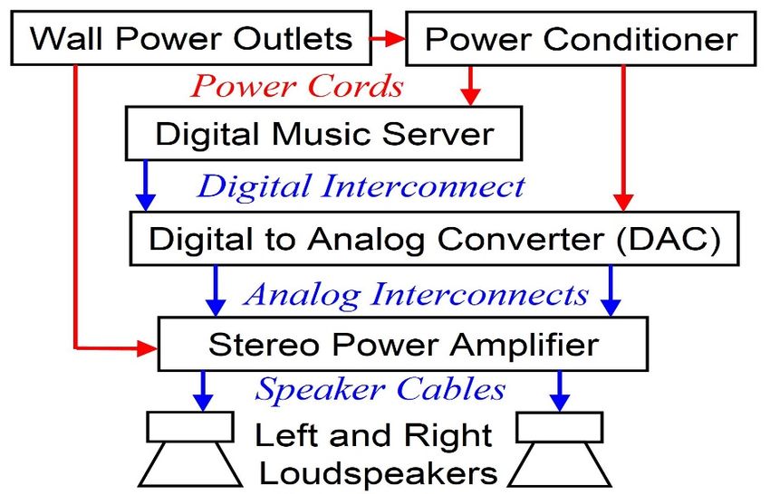
instruments and their acoustic surroundings, reproduced with amazing timbral detail. HEAcomponents are already close to perfection in standard specifications—for example, the amplifier used in the present work has a frequency response of DC to 1 MHz ±1 dB, unweighted signal‐to‐noise ratio of 97dB, and ~0.01% total distortion. Sonic dissimilarities between HEA components arise from subtle time‐domain differences; and improvements in overall system performance come from meticulous setup and tuning, and careful attention to details such as the interlinking cables [10]. The next section describes the audio system used in this work in complete details, so that the system and the experiment can be replicated by other research groups. By using this accurate audio system, it was possible to prove that the phantom images of instruments in the recreated soundstage appear not only at different azimuthal locations (left/right lateral separations) and depth (distance behind/in‐front of loudspeaker plane), but occur at different elevations (heights of images above floor). Most audio professionals do not believe that elevation can or should be naturally reproduced in two‐channel stereo. The present experimental result settles that debate. This effect has been demonstrated in private settings and in conventions, but the present work provides concrete proof through IRB (Institutional Review Board) approved controlled blind tests. The results provide a scientific underpinning to anecdotal claims by HEA enthusiasts, and reinforces early work on imaging using the Blumlein‐microphone technique at the former Instituut voor Perceptie Onderzoek (at Eindhoven Technical University in The Netherlands) [11]. 2. INSTRUMENTATION AND METHODS 2.1 Description of Audio System used in the Experiment Figure 1 shows the image (upper panel) and block diagram (lower panel) of the audio system used in the experiment. The main components (text boxes in the block diagram) are interlinked by various types of cables (arrows). The amplifier is plugged directly into a grounded wall outlet. The server and DAC are plugged into a Tice Audio® Microblock® power conditioner with floating ground. The music server is a Bryston® BDP‐1 Digital Player®. This fed a 1.5m Straightwire® Infolink® digital interconnect through an AES/EBU XLR connector (abbreviations stand for AES: Audio Engineering Society; EBU: European Broadcasting Union; XLR: external line return). The digital feed goes into a Berkeley Audio Design® Alpha DAC® Series 2. This DAC (digital‐to‐analog converter) has two isolated buffered pairs of analog outputs—single ended RCA (Radio Corporation of America) and balanced XLR. The balanced XLR outputs fed a pair of 0.5 m long balanced XLR‐to‐XLR Straightwire® Virtuoso® analog interconnects; the RCA outputs were not used. The analog interconnects fed a Spectral® DMA‐250S Studio Universal Amplifier®. The measured C‐weighted sound level at listener position peaked at 72 dB SPL. The amplifier’s output was bi‐wired to a pair of ProAc® Response® D2 loudspeakers through 3m long Straightwire® Maestro® II loudspeaker cables. These cables were terminated by optimized RC networks (R=18 in series with C=3.3 nF at the tweeter terminals and R=18 in series with C=5 nF at the woofer terminals) to suppress reflections back toward the amplifier. The loudspeakers were mounted on Target® HJ20/T® stands with lead filled columns, and with spikes on the top and bottom plates to suppress recoil.
Figure 1. Image (upper panel) and block diagram (lower panel) of the audio system used in
the experiment. Major components are labeled in the image. Interlinking cables and components
not used in the experiment (such as the FM tuner, turntable, and amplifiers powering
subwoofers, etc.) are unlabeled in the image.

   Loudspeaker distances (from front‐face centers) were: 1.88 m to the back wall, 1.69 m to
side walls, and were mutually separated by 2.08 m between left and right units. The room
has a 56 m2 area with 1.37 length‐to‐width aspect ratio, and 2.7m ceiling height. The back
wall was lined with 1.22 m tall air‐spaced rock‐wool panels (average thickness of 245 mm)
fronted by Roomtune® panels and louvres of wooden strips. The floor is covered with very
dense and thick nylon carpeting atop thick padding, with a double layer of carpeting (total
thickness of ~40 mm) over 2 m2 areas where the first reflections from the floor occur.
General guidance for setting up suitable audio systems can be found in [12]. As a rule of
thumb, the loudspeakers should be spaced about 2 m apart in a room large enough to ensure
that the loudspeakers are distanced by at least 2 m from the back and side walls, and at least
5 m from the far wall; the listener can be seated at 2.5–4 m distance from both loudspeakers
equidistantly.

2.2 Human‐Research Ethical Approval

   The experimenter (author) completed a Collaborative Institutional Training Initiative
(Citi Program) course (Completion Date: 29‐Apr‐2018; Expiration Date: 28‐Apr‐2021;
Curriculum Group: Human Research; Course Learner Group: Social & Behavioral
Researchers). The research proposal for this study was reviewed on 03‐May‐2018 by the
Office of Research Compliance of the University of South Carolina Institutional Review Board
(ethics committee). All experiments were conducted in compliance with the reviewed
proposal.

2.3 Statistical Method

   The experiment had 1 degree of freedom, for which the ‘chi‐squared value’ is given by:
   χ2 = (C − T/2)2/(T/2) + (I − T/2)2/(T/2), where T is the total number of trials, C is the
number of correct judgments, and I is the number of incorrect judgments. The standard
critical value for chi‐squared is 3.84, which corresponds to a right‐tail probability of p = 0.05
for occurrence by random chance (i.e., a certainty of 95%). As will be seen below, the present
experimental result produced a value of χ2 =25.14, well in excess of the critical value (the
probability that the result occurred by random chance is only 0.0000005332).

3. SOUND LOCALIZATION AND STEREO IMAGING

   Let us now review the mechanisms for localization—the process used by our auditory
system to determine the locations of natural sounds—and see how these mechanisms relate
to the workings of spatialization in reproduced stereo sound [13]–[15]. It should be noted
that the term spatialization is sometimes used for dimensionality created through artificial
processing, wave field synthesis, ambisonics, and the various implementations of surround
sound [16]–[18]. However, the present work is concerned with the 3D sound that unfolds
naturally in HEA through a two‐loudspeaker setup and recordings made with two
microphones without artificial signal manipulation. The key to sonic dimensionality is to
maintain the highest signal integrity at every step in order to preserve the time‐domain
fidelity to the subtlest detail. The reasons for this will become apparent in the following
subsections. We will start with the determination of depth.

3.1 Determination of depth

       There are four main mechanisms that provide distance cues: (1) Fall off of intensity
with distance for familiar sound sources, e.g. someone’s voice. (2) Preferential absorption of
high frequencies as sound travels through air, resulting in a duller sound with increasing
distance. (3) The ratio Id/Ir of direct sound intensity Id to reverberant sound intensity Ir, with
the sound taking on a more reverberant quality with increasing distance. (4) The time delay
gap between the direct sound and the arrival of the first strong (usually ground) reflection,
with the gap diminishing with distance. When listening to unfamiliar sounds, the first two
mechanisms play a reduced role.
In reproduced sound, depth is portrayed if the recording has faithfully captured the
reverberation and temporal structure, and the audio system’s time‐domain response does
not mask this information. Note that two channels are not essential for portraying depth;
monophonic reproduction can convey depth too.
3.2 Determination of azimuth
Azimuth refers to the horizontal‐plane left‐right angle, with straight in front
designated as zero degrees. Sound from a source that is not directly in front will arrive at
the two ears with unequal intensities (Interaural Level Difference or ILD) and at unequal
times (Interaural Time Difference or ITD). These differences are analyzed respectively in the
Medial Superior Olive (MSO) and Lateral Superior Olive (LSO) within the Superior Olivary
Complex in the brain. In addition to ILD and ITD, the primary spectral mechanism for
elevation determination (see below) also provides azimuthal cues.
Stereo recording techniques where the microphones are spaced apart—such as the A‐
B or ORTF (Office de Radiodiffusion Télévision Française) methods—introduce level and time
differences between the left and right channels. Recording techniques with coincident
microphones—such as the X‐Y or Blumlein methods—maintain synchronicity between the
channels and azimuthal separation is accomplished mainly through frequency dependent
level differences. The Blumlein technique uses “figure‐8” microphones (which are less
directional than cardiod microphones) and thereby picks up more of the ambient reflected
sounds. As discussed above this is necessary to convey depth. As discussed below, this
capturing of ambient sound also appears essential for conveying elevation.
3.3 Determination of elevation
One widely accepted elevation‐localization mechanism [13]–[15] is based on
constructive peaks and destructive dips in the spectral response, referred to as the HRTF
(head related transfer function; e.g., see Figure 4 in [13]), caused by interference between
sound reaching the ear canal directly and through multiple reflections off of the pinna and
head. This HRTF spectral mechanism works for broadband and high‐frequency‐content
sounds, especially above ~3 kHz where wavelengths become comparable to the pinna. The
HRTF, which is neurologically analyzed by a bank of notch‐detecting pyramidal neurons in
the Dorsal Cochlear Nucleus (DCN) in the brain, depends sensitively on the elevation of the
sound source but also on the azimuthal angle. Hence besides source elevation, one can also
differentiate left‐right sound direction with just one ear, although not as accurately as with
the ITD and ILD mechanisms.
Binaural recordings, which are intended for playback through earphones, are made
with a dummy head to embed an HRTF in the recording. Because this HRTF belongs to the
dummy and not to the listener, this never quite succeeds in placing images of instrumentswhere they should be, i.e. in a soundstage in front of the listener, instead of in and around the head. Most audiophile stereo recordings are meant for loudspeakers and do not utilize a dummy head (or other purposeful interference scheme) during recording nor have an artificially embedded HRTF. Despite this, some recordings played on a good audio system clearly portray elevation, as presented below. This shows that the HRTF spectral model of human elevation localization is not the whole story. Moreover, humans can localize the elevation of narrowband and low‐frequency (f
3.4 Reflection management in the auditory system and stereo imaging

        Imagine the roar of the tiger that is some distance away and a cliff off to the side that
strongly reflects the roar back in your direction. Your survival strategy will depend on
knowing whether these are separate roars from two different tigers or just one roar plus a
reflection. If the second sound seems like a reasonable copy of the first (as is the case for a
reflection) and if its delay and intensity are physically consistent with it being a reflection,
the brain integrates the two sounds into a single auditory event so you can focus on the real
threat—just one tiger. In this case, the second sound (presumed to be a reflection) is blocked
from your awareness but its intensity is perceptually added to the first sound. This is the
precedence effect (formerly referred to as the Haas effect).
        Since sound intensity falls off with distance, a cliff that is farther away should
produce a fainter reflection of the tiger’s roar and this reflection should arrive with a longer
delay. Thus if the second sound is much delayed and yet too loud for it to be physically
consistent with a reflection, the brain assumes that there is a second tiger, not a reflection,
and segregates the second sound into a separate auditory stream, which you become aware
of as an echo.
        Even with no cliffs present, there are always innumerable early reflections from the
ground and other close‐by objects. In this situation our auditory system integrates all these
early reflections into a single stream that is imaged at the approximate “center of gravity”
of the direct and all reflected sounds combined. This is the region of summative localization.
        Summative localization is the reason why stereo sound works. When an instrument is
midway between the left and right microphones during recording, during play back its sound
will start from both loudspeakers at the same time with equal loudness. Summative
localization then creates a phantom image of the instrument floating in the air midway
between the left and right loudspeakers. An instrument off to one side during recording, will
result in differences in loudness and/or delay, so that during playback the image will appear
off center. This is how left‐right (azimuthal) separation of images takes place. The
mechanisms leading to depth and elevation differentiation were discussed earlier.
        This neurological reflection management scheme has other complexities and finer
categories, and the boundaries dividing those categories depend on the level and other
characteristics of the sound [27]. However, for our present purpose it will suffice to consider
these three broad categories: (1) early reflections ( 80 ms) leading to echoes. All three effects are vividly demonstrated at
http://boson.physics.sc.edu/~kunchur/reflections/index.htm.              (Although         these
demonstrations will work to varying extents on any stereo playback system including a
laptop computer, for optimum effectiveness please see section 2.1 for information on audio
system setup.)

3.5 Loudspeaker placement and room effects

       From the above discussion (especially the last four subsections) it should be clear that
for a recording to naturally capture and convey 3D spatialization, each microphone
(preferably just two or few) needs to pick up sounds from all the instruments as well as the
reverberation and other classes of reflected sound. For this, the microphones need to be far back so as to have a complete “view” of the musical performance space. Typical popular recordings are recorded with microphones in close (
recording only once. There was no opportunity for prior listening for the purpose of practice
or training. They were not informed about the title or label of the recording, or given any
other information. 29 human subjects (16 males + 13 females) ranging in age from 18–80
years participated. None of these listeners had ever experienced HEA before or had a special
interest in audio. About half (15) played or listened to music seriously. None of them had any
prior expectation as to which instrument should be higher. The recording played was the
Buddy Bolden Blues track on the CD (compact disk) “Test Record 1: Depth of Image” by the
label Opus 3 released in 1984. Of the 29 subjects, 28 judged the trumpet to be higher and 1
judged both instrument elevations to be the same. This computes to a chi‐squared value of
= 25.14 (see discussion of the formula in the “Statistical Method” subsection). This is well
above the critical value of 3.84 commonly used in psychoacoustic testing, and corresponds
to a certainty of 99.9999467% (i.e., p=0.0000005332) and there is less than one chance in
a million that this score could have resulted from fortuity.
After all listening tests were completed, the Opus 3 company was contacted for
particulars of their recording. They confirmed that there was no manipulation of the
recording to artificially alter image elevation. They had used the Blumlein microphone
technique (consisting of two figure‐8 microphones), which is adept at picking up ambient
reflections. Furthermore, they confirmed that the trumpet was indeed located higher than
the banjo during the performance that they recorded. So the perceived relative elevation
agreed with the original physical configuration.
5. CONCLUSIONS
This experiment conclusively proves that a correctly set up two‐channel stereo system
can in fact portray not only depth and lateral width (azimuth), but also elevation for
appropriately recorded material. The present experiment should be distinguished from ones
in which spectral notch filtering and directional band boosting have been employed to
artificially manipulate image elevation [28]. Auditory elevation‐localization models that
include temporal/spectral mechanisms due to torso and shoulder reflections, in addition to
the HRTF‐spectral mechanism, explain why height differentiation might be perceived in
purist recordings that have not been artificially manipulated.
For live performances with acoustic instruments, this work underscores the value of
microphone techniques that record from a distance the entire sonic space (including the
reverberation and other classes of reflected sounds) to capture the three dimensionality in a
natural way, as long as time‐domain accuracy is maintained during playback.
6. ACKNOWLEDGMENTS
The author acknowledges the following individuals for useful communications and advice:
Peter Lindenfeld, Wilbert Van Meter Johnson, Joe Azar, Jan‐Eric Persson, Reginald Bain, and
Grigory Simin, and also thanks both referees for their valuable input.7. REFERENCES
1. van Maanen HRE. “Temporal decay: a useful tool for the characterisation of resolution of audio
systems?”. AES Preprint 3480 (C1‐9), presented at the 94th Convention of the Audio Engineering
Society in Berlin (1993).
2. van Maanen HRE. “Requirements for loudspeakers and headphones in the ‘high resolution audio’
era”. presented at the Audio Engineering Society’s 51st International Conference, Helsinki,
Finland, August 22–24 (2013).
3. van Maanen HRE. “Is feedback the miracle cure for high‐end audio?”. 31 January (2019).
https://www.temporalcoherence.nl/cms/images/docs/FeedbackHvM.pdf
4. Woszczyk W. “Physical and Perceptual Considerations for High‐Resolution Audio”. Audio
Engineering Society Convention Paper 5931 Presented at the 115th Convention, New York, New
York, October 10‐13 (2003).
5. Thiele N. “Phase considerations in loudspeaker Systems”. Audio Engineering Society Convention
Paper 5307 Presented at the 110th Convention 2001 May 12‐15 Amsterdam, The Netherlands
(2001).
6. Stuart JR. “Coding for high‐resolution audio systems”. J. Audio Eng. Soc., vol. 52, 117–144 (2004).
7. Stuart JR., Craven PG. “A Hierarchical Approach to Archiving and Distribution”. Presented at the
137th Convention of the Audio Engineering Society, Los Angeles, U.S.A., October 9‐12, convention
paper 9178 (2014).
8. Jackson HM, Capp MD, Stuart JR. “The audibility of typical digital audio filters in a high‐fidelity
playback system”. Presented at the 137th Convention of the Audio Engineering Society, Los
Angeles, U.S.A., convention paper 9174, October 9‐12 (2014).
9. Reiss JD. “A Meta‐Analysis of High Resolution Audio Perceptual Evaluation”. J. Audio Eng. Soc.,
vol. 64, No. 6, pp. 364‐379, June (2016). DOI: http://dx.doi.org/10.17743/jaes.2016.0015
10. Kunchur MN. “Signal alterations in analog interconnects”. Submitted manuscript currently under
review. Preprint posted at: http://boson.physics.sc.edu/~kunchur//papers/Interconnect‐
measurements‐‐Kunchur.pdf
11. Grimm E, “Checkpoint Audio: Professional Audio Test Reference”. Buren: Contekst Publishers
(2001), ISBN 9080611115.
12. Harley R. “The Complete Guide to High‐End Audio”. Acapella Publishing, fifth edition (2015), ISBN‐
10: 9780978649364, ISBN‐13: 978‐0978649364, ASIN: 0978649362.
13. Hartmann WM. “How We Localize Sound”. Physics Today vol. 52, 24 (1999);
https://doi.org/10.1063/1.882727
14. Blauert, J. “Spatial Hearing: The Psychophysics of Human Sound Localization”. The MIT Press
(Cambridge, MA), revised edition (1997).
15. Risouda M, Hanson J‐N, Gauvrita F, Renarda C, Lemesrea P‐E, Bonnea N‐X, Vincent C. “Sound
source localization”. European Annals of Otorhinolaryngology, Head and Neck diseases vol. 135,
259 (2018).
16. Zotter F, Frank M. “Ambisonics: A Practical 3D Audio Theory for Recording, Studio Production,
Sound Reinforcement, and Virtual Reality”. Springer Topics in Signal Processing Book 19, Springer
(2019). ASIN : B07RC5FLYG
17. Hamasaki K, Nishiguchi Tm, Okumura R, Nakayama Y, Ando A. “A 22.2 Multichannel Sound System
for Ultrahigh‐Definition TV (UHDTV)”. SMPTE Motion Imaging Journal vol. 117, 40–49 (2008).18. H. Jo, W. Martens, Y. Park and S. Kim, “Confirming the Perception of Virtual Source Elevation
Effects Created using 5.1 Channel Surround Sound Playback,” Proc. ACM SIGGRAPH 9th Int. Conf.
on Virtual reality Continuum and Its Applications in Industry (VRCAI), Seoul, Korea. (2010).
19. Algazi VR, Avendano C, Duda RO. “Elevation Localization and Head‐Related Transfer Function
Analysis at Low Frequencies,” J. Acoust. Soc. Am., vol. 109, 1110 (2001).
20. Lee H. “Evaluation of the Phantom Image Effect for Phantom Images”. In 3rd International
Conference on Spatial Audio (ICSA), Graz, Austria (2015). http://eprints.hud.ac.uk/25887/
21. Lee H. “Sound Source and Loudspeaker Base Angle Dependency of Phantom Image Elevation
Effect”. J. Audio Eng. Soc. vol. 65, 733 (2017). DOI: https://doi.org/10.17743/jaes.2017.0028
22. F. Asano, Y. Suzuki, and T. Sone, “Role of Spectral Cues in Median Plane Localization”. J. Acoust.
Soc. Am., vol. 88, 159 (1990). https://doi.org/10.1121/1.399963
23. de Boer K. “A Remarkable Phenomenon with Stereophonic Sound Reproduction”. Philips Tech.
Rev., vol. 9, 8 (1947).
24. Damaske P., Mellert V. “A Procedure for Generating Directionally Accurate Sound Images in the
Upper Half‐Space Using Two Loudspeakers”. Acustica, vol. 22, 154 (1969).
25. Frank M. “Elevation of Horizontal Phantom Sources,” Proceedings of DAGA 2014, (Oldenburg,
Germany, 2014).
26. Cabrera D, Tilley S. “Vertical Localization and Image Size Effects in Loudspeaker Reproduction”.
In Proc. AES 24th Int. Conf. on Multichannel Audio, The New Reality (2003).
Permalink: http://www.aes.org/e‐lib/browse.cfm?elib=12269
27. Everest FA, Pohlmann KC. “Master handbook of Acoustics”. McGraw Hill, sixth edition (2015),
ISBN 978‐0‐07‐184104‐7.
28. Chun CJ, Kim HK, Choi SO, Jang S‐J, Lee S‐P. “Sound source elevation using spectral notch filtering
and directional band boosting in stereo loudspeaker reproduction”. IEEE Transactions on
Consumer Electronics vol. 57 , 1915 (2011).You can also read