2022 Anthem/Cornerstone Manual - Vegatouch
←
→
Page content transcription
If your browser does not render page correctly, please read the page content below

2022 Anthem/Cornerstone Manual

                             1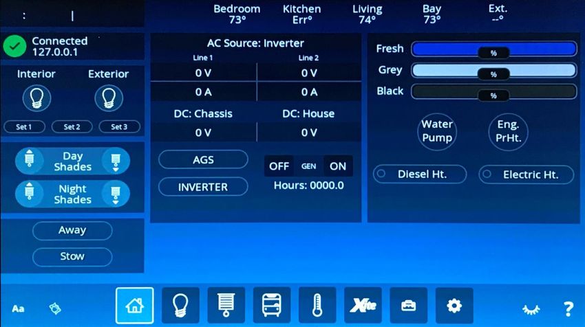
All information contained in this document is        Settings
subject to change without notice.               21          Display

                                                22          Software
2      TABLE OF CONTENTS                        23          Sleep

                                                24          User/General Settings
       Home                                     25          User/Notifications
3                  Home Screen Overview         26          User/System
6                  Away/Stow                    32          Images
7                  AGS                          33          Pairing
8                  Inverter

                                                34   Cloud Service Subscriptions
       Lights

9                  Basic Mode
                                                     Other Multiplex Hardware
10                 Control Mode
                                                35          5” Lynx Screen (TruTank)

                                                37          Multiplex Operation
       Shades
                                                38          SSP18 Switch Panels
11                 Basic Mode
                                                39          SSP17 Switches
12                 Control Mode
                                                40          G6A

                                                41          G12
       Coach
                                                42          Networking
13                 Exterior Lights
                                                43          Network Troubleshooting
14                 Slides/Awnings
                                                44          Connecting Vegatouch to WiFi

                                                45          Connecting Mobile Devices
       Climate
                                                46          Winegard Router Replacement
15                 Manual Mode
                                                49          System Diagrams
16                 Schedule Mode

18     Xite

19     Utilities

                                                                                           2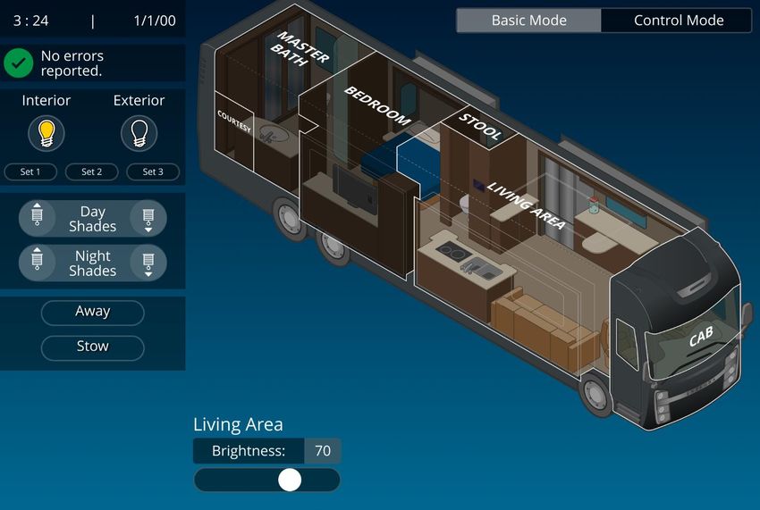
Home Screen Overview

          Temperatures by zone.

            Tap to select your desired screen    Tap to put the screen to
                 cleaning mode option.            sleep. Tap BLACK OUT
                                                (from the sleep screen) to
                                                    make the screen go
                                                     completely dark.

                                                Tap the Question Mark to access
                                                available help topics. Tap a topic
Tap to add labels to the screen icons.                    to learn more.

                                                                                     3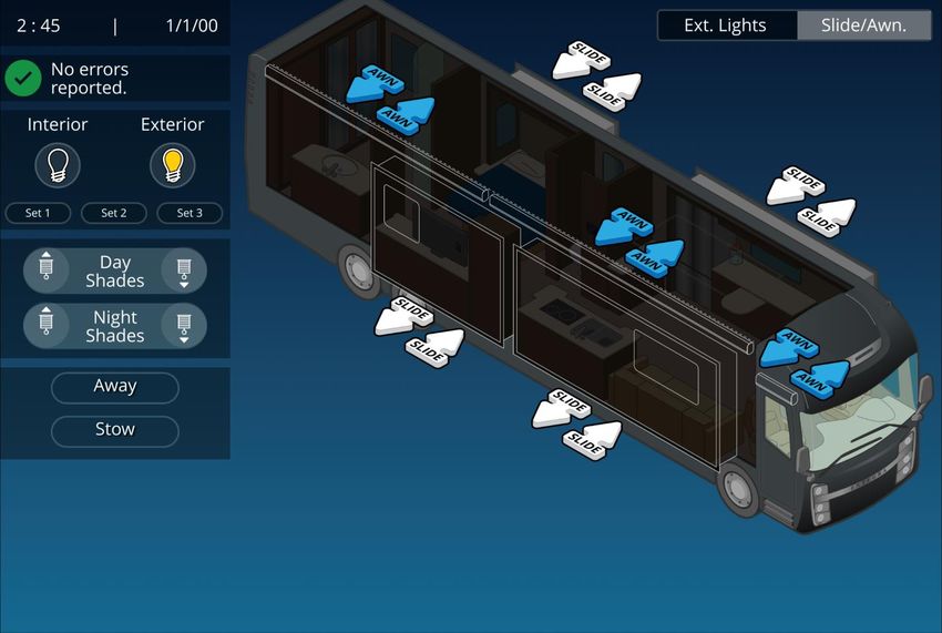
The Message Center gives you quick, easy access to warnings and notifications being reported by many
1
    systems in your coach. Tap the Message Center to expand the screen. Tap the arrow in any message
    entry or the Message Glossary List Button to view expanded information.

2   Light Master –                                 Tap to turn All Lights off.

                              Tap to return All Lights to their previous state. Press and Hold to
                                                       turn All Lights On.

                              Press and Hold a SET button to save the current state of lights and
                                           name it. Double-tap to only rename it.

                              Tap a SET button to turn lights On (and off) to your pre-set choice.

                     Tap to enter the Message Center.

1

2
                                   Tap the speaker to
                                   Mute/Unmute specific alarms.

                                                        Expanded info
3

                          4

    Shade Master – Tap the Up/Down shade icons to operate all Day/Night shades. Note: For privacy
3
    reasons, Master Bathroom and Stool Room shades cannot be ran in the Up direction from Vegatouch.

    Away/Stow – Tap Away or Stow to enter Away or Stow mode. Press and Hold Away or Stow to enter the
4
    Action settings screen (See Page 6). Tap Return when you have returned to the coach and want to exit
    Away or Stow mode.

                                                                                                           4
5   Inverter, Shore and Generator power readings (AC power).

6   DC Power data (battery power).

7   AGS (Auto Gen Start) – Tap to Enable/Disable AGS. Press and Hold to enter the AGS Settings Menu.

8   Inverter – Tap to Start/Stop the Inverter. Press and Hold to enter the Inverter Settings Menu.

9
    Generator – Press and Hold On or Off to operate the generator. The generator hours are saved to the
    system, not to the generator itself. Tap the hours tally to enter your desired gen hours.

                         5

                 6

                     7

                     8
                                         9

                                                     Tank Levels Display.

                                       100%

                                       100%

                                       100%

                                                                Tap to toggle Water Pump or Engine
                                                                          Preheat On/Off.

                                              Aqua-Hot heat source selectors.

                                                                                                          5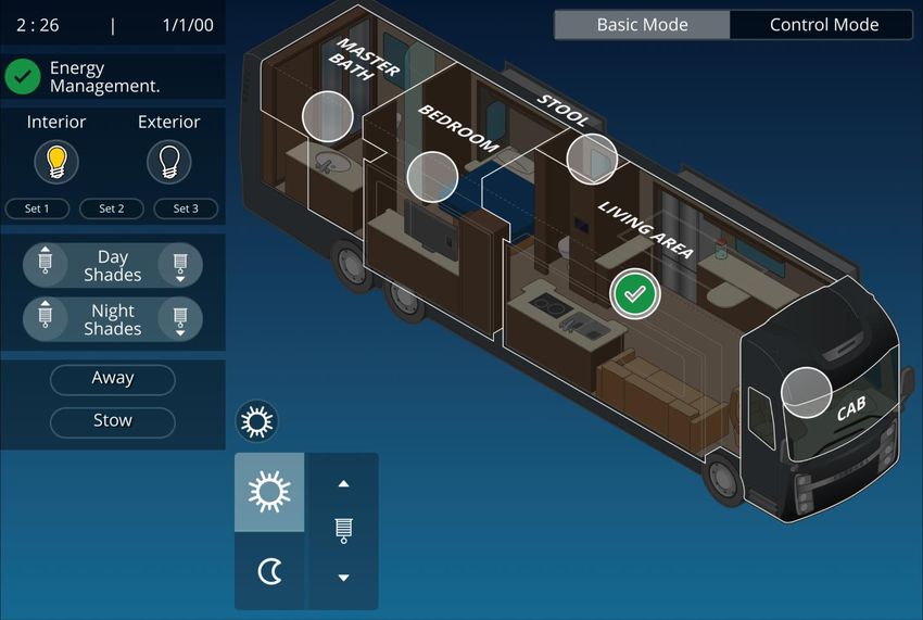
Home – Away/Stow

    The Away/Stow Action screen is accessed by holding Away or Stow on the Home Page.

    This screen will allow you to customize how your coach will function while you are away regarding AV,
    Lights, Shades, Water pump and Climate Control operations. Swipe Up/Down to scroll through all of
    the options. 50 Amp shore power or AGS required for Climate Control.

                                                                 3
         1

             2

                                                                                                        Scroll

    Lock Doors Delay – Tap the check box to enable. The doors will lock at after a specified amount of time
1
    (up to 120 seconds) once Away or Stow has been tapped.

    Climate Control – If this is left unchecked, current Climate Control settings will stay active and there will
2
    be no changes. Once it has been checked, Turn on AC and Turn on Heat parameters will become
    available to select (as shown).

3   Swipe Up/Down to scroll through all of the options. Select On/Off or Up/Down for each function.

                                                                                                                    6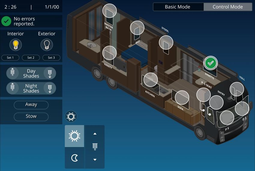
Home – AGS

    You can easily control when the generator will automatically start by adjusting the settings below.

    The AGS Dialogue screen is accessed by holding AGS on the Home screen.

1   Tap On or Off to enable/disable AGS.

    Insufficient Shore Power – The generator will automatically start if shore power becomes insufficient to
2
    handle the required load.

3
    Volt Based Start – Tap the check box to enable. The generator will start when the system voltage
    reaches a desired low point. Tap the selector box to adjust the set point.

4   Climate Start – Tap the check box to allow the generator to start based on climate energy needs.

5
    Quiet Time – Tap the check box to enable. Tap the selector boxes to enter your desired quiet hours
    where the generator will not run. If Quiet Time Prefill is selected, the generator will start and charge the
    system before the Quiet Time period begins.

6
    Exercise – Tap the check box to enable allow the generator to start periodically to exercise. Tap the
    Day/Min boxes to choose your desired intervals and run time.

                             1

        2

             3

        4

             5

         6

                                                                                                                   7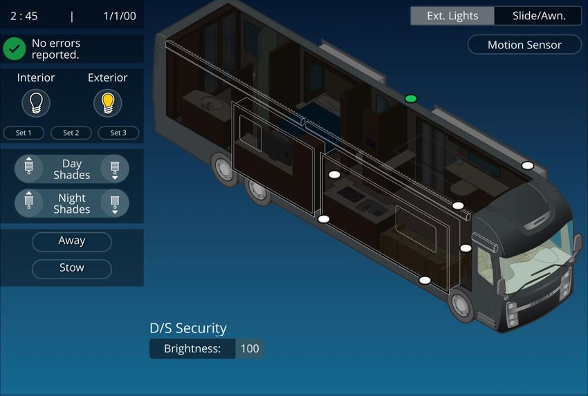
Home – Inverter

1   Default – Tap the default button to reset all Inverter settings back to Entegra defaults.

2   Inverter – Tap to toggle the inverter On/Off individually (Red = Off, Green = On).

3   Charger – Tap to enable or disable the charger.

    Battery Maintenance – Tap the button to perform Battery Maintenance as needed. Note: This process
4
    will take roughly 5 hours to complete, and 50-amp shore power is required.

5   Inverter information – Technical information regarding your inverter and inverter bridge.

    Battery/Charger Setup – Tap the selection boxes to customize the values of your charging system. For
6
    more information, please see your inverter’s user manual or contact Entegra for recommended settings.
    Note – Inverter Amps was added to Nebula Release V1.4.7. Inverter Amp selection will default to 30 if a
    coach has 30-amp inverter options selected, otherwise it will default to 50.

                                                                                                1

                                                                                                2

                                                                                                3

                                                                                                      4
    6

                                                                                                      5

                                                                                                              8
Lights – Basic Mode

    Tap the lighting mode selector buttons to choose between Basic Mode (room based) or Control Mode,
1
    which allows for more customized lighting options.

    Simply Tap an area on the coach graphic to toggle the room lights ON/OFF. Adjust the brightness of the
2
    room by sliding the fader to your desired level.

                                                                                     1

                                                                                2

                                                         Tap room to select

                                                     2

                                                                                                             9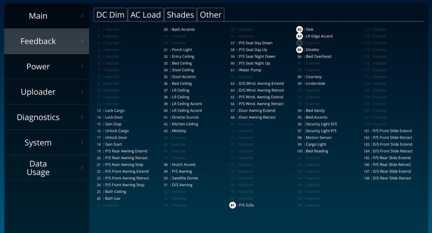
Lights – Control Mode

    Control mode allows for the complete control of every light in the coach. Simply tap the graphic of the
1
    light that you want to toggle On/Off or slide the fader to adjust brightness.

    Light indicators will change from White (Light Off) to Green (Light On) when tapped. Double tap a light
    indicator to select it without turning it on/off or affecting its brightness. Once selected, this light will
    stay fader adjustable for 15 seconds or until another light is selected, whichever comes first. Note:
    deselect times can be adjusted by clicking on the Settings button/User tab.

                                                                            1

                                                       1

                                                                                                                   10
Shades – Basic Mode
Tap the Shades mode selector buttons to choose between Basic Mode (room based) or Control Mode,
1
which allows for more customized shade control options.
To operate the shades, tap the round shade selector icon in the room that you would like to control (a
2
green checkmark will appear once selected). Then, simply tap the Sun or Moon icon to select Day or
Night shades and tap the Up/Down arrow to fully raise or lower the selected shades. If you do not wish
to fully raise/lower the shades, tap the same arrow again to stop the shade’s travel. Once a shade has
been selected, you will have 15 seconds to operate the shade before the room becomes deselected.
1
2
Current Mode Indicator/Selector
2
11Shades – Control Mode
Control mode allows for the complete control of every shade in the coach.
To operate the shades, tap the round shade selector icon for the shades that you would like to control (a
1
green checkmark will appear once selected). Then, simply tap the Sun or Moon icon to select Day or
Night shades and tap the Up/Down arrow to fully raise or lower the selected shades. If you do not wish
to fully raise/lower the shades, tap the same arrow again to stop the shade’s travel. Once a shade has
been selected, you will have 15 seconds to operate the shade before it becomes deselected.
1
Current Mode Indicator/Selector
1
12Coach – Exterior Lights
The Exterior Lights screen will be selected by default. Tap Slide/Awn if you wish to navigate to the
1
Slides/Awnings screen. Note: a warning message will appear once Slide/Awn has been tapped.
2 Tap Motion Sensor to activate motion light functionality.
Tap the graphic of the light that you want to toggle
3
On/Off. Light indicators will change from White (Light Off)
to Green (Light On) when selected. The brightness
for exterior lights is not dimmable.
1
2
3
13Coach – Slides/Awnings
Engage the parking brake before operating the Slides/Awnings.
1
Tap the arrows to Extend or Retract the desired awning. It will stop automatically at the end of the
cycle. A stop button will appear after an Ext/Ret button is pressed (not shown). Tap the Stop button to
stop the awning at its current position. To operate the Window Awnings, tap their specific EXT or RET
buttons.
2 Press and Hold the arrows to Extend or Retract the slide rooms. Release the arrow to stop.
1
2
1
14Climate – Manual Mode
1 Climate Mode - Tap to cycle through and select a climate mode (Auto, Cool, Heat or Off).
Tap this icon to apply a particular zone’s climate settings across all zones.
2 Tap the icons to select your desired Fan Speed, AquaHot and Heat Pump settings.
3 Set Temp - Tap the arrows to select your desired temperature.
4
Floor Heat - Tap the arrows to select between off or set between the temperature to between 32-100
degrees.
5 AquaHot Heat Source – Tap to choose a heat energy source (Diesel or Electric).
1
2
Mid Rear
3 5
c
4
15Climate – Schedule Mode
Schedule Mode – Tap the Day/Night schedule button to choose Day/Night mode and setup your desired
start times and personal climate settings for each zone. Day Schedule mode will stay active until Night
Schedule begins and vice versa.
The button that switches between day and night mode will go grey when that mode is active. So, if
schedule mode is in DAY MODE, when that button displays the sun, the button will also be grey. At the
same time, if the button displays the moon, it will not show as highlighted because that mode is
inactive.
Mid Rear
16Xite
1 Tap Xite to load the radio controls. These buttons will operate the Xite Radio built into the dash.
1 Power Toggle
172 Tap the Cameras button to display the Camera Angles screen.
3
Tap the camera angle that you wish to view. The camera feed will display on the TV in the zone that you
have chosen (house mode). The rear-view camera will allow for additional angles that can be chosen.
Tap Enable to have the display cycle through the left, right, rear and front camera angles periodically
4
(parking brake required). Drag the slider to select the time period that the camera angle will change (5 -
60 seconds).
5 Tap Toggle Camera Display to toggle the camera view on the Xite screen.
2
5
3
4
18Utilities
The Utilities screen houses the controls for A/V Off, fans, and locks. All of these functions can be added
to the Home Screen by using the Edit Home feature.
Tap to Add/Remove custom utilities buttons. Selected
buttons will be outlined in green and will appear once
Save and Close (not shown) has been tapped.
Edit Home – To add the icons to the Home page simply Tap the icons to Select (Red) or Deselect (Gray)
each of them. In this example, the Panel Lights button has been selected and will be available for use on
the Home screen once the user has re-pressed the pencil button. Tapping the Reset Home button will
deselect all of the icons and remove them from the Home page.
19Fan Controls – Press and Hold any Fan button to bring up the Fan Dialogue screen.
Tap the controls to setup fan functionality to your specifications (direction, speed, timer, etc.).
Vent Fan Controls
• Power Button: If off, the power button will put the vent fan control back to its previous
state. If on, the power button will turn the fan off, the lid will not be affected.
• Low/Med/High Fan Speeds: The fan will go to desired speed and lid will go up. If off, the fan
direction will go to exhaust. If on, the fan direction will not be affected.
• Exhaust/Intake: Fan will go to desired direction and lid will go up. If off, the fan speed will
go to Med. If on, the fan speed will not be affected.
• Up: Will put lid up.
• Down: Will put lid down. If on, fan will turn off.
• Timer: Turns fan off, puts lid down after timer runs out. Times that can be selected are 5-60
minutes in 5-minute increments.
• Auto Mode: If the set point is 2 degrees lower than that zones ambient temperature then
the fan will go to exhaust and high and lid will open. If the set point is 2 degrees higher than
that zones ambient temperature, then the fan will turn off and lid will close.
20Settings/Display
Display will be the default tab when you click on the Settings button. Click another tab to navigate away
from the Display tab.
Press and Hold this icon to reset a particular tab back to default settings.
Slide the fader to adjust screen brightness.
Tap to select or enter your desired
Alarm Mute settings.
21Settings/Software
Any required software updates will be done wirelessly via the cloud (your coach must be connected to
the internet to receive an update).
Check for Update – Tap to check for available system updates.
2 Update – Tap to install the latest update.
3 Restart Screen – Tap to restart the Vegatouch screen.
1 3
Current Version
2
22Settings/Sleep
This screen will be used to select your desired display options for the Sleep screen.
Tap the Check Box to enable the slideshow/sleep screen. Slide the fader to adjust the time period of
1
inactivity required before the slideshow/sleep screen begins.
Screensaver Display Items – Tap the items that will display on the Screensaver. Enter a time period
2
where you would like the screen to sleep each day. When the current time is within the sleep time
parameters, the screen will bypass the screensaver page and go completely black.
Show Climate Zones – Choose the individual zone temps that you would like to display on the sleep
3
screen.
1
2
3
23Settings/User/General Settings
The General Settings component of the User tab will allow you to change the color scheme of
1
Vegatouch. Simply tap the color selector windows to customize the top and bottom color scheme.
Light Select – Slide the fader to select the amount of time that lights will remain selected once tapped
2
(1-30 seconds).
3 Default – Tap to scroll through several preset Vegatouch color schemes.
3
1
2
c
24Settings/User/Notifications
Use this screen to setup which coach conditions will result in a notification on the Nebula app. Tap the
1
check box for each condition that you’d like to be notified about. Notice: no notifications will be sent if
the first box (Notify me if an error occurs) has not been checked.
1
Tap to adjust how often Notifications will occur.
25Settings/User/System
Tapping Settings/User/System will result in the following Settings menu appearing. Note: You can also
reach this menu by pressing and holding the Vegatouch Question Mark for 2 seconds.
1 Tap to select the Floorplan or Model.
This screen will display all the software versions related to your coach. Always have this version
information available when calling for Technical Support.
Current
Screen
1
41
2 3 4
2 Floorplan Options - Tap to Enable/Disable available floorplan options.
Show Mode – Once tapped, enter the passcode to enter Show Mode for use at Trade Shows. This mode
3
will disable certain functions and is not meant for the end user.
4 EMS Override – Tap to Override the coach’s built-in Energy Management System. Once the override has
been enabled, the Transfer Switch Override button will appear just above the message center. Tap it to
disable the override.
265 6
5 Beta Testing – This mode should not be used without consultation from Firefly Integrations.
6
Remote Help – Tapping Remote Help will allow Firefly Integrations to connect
remotely for technical assistance. Once enabled, a Remote Help Message and
session ID number will appear just above the message center. Provide this
number to Firefly to start a remote help session. Tap the message to discard it.
7 Tabs – Tap the appropriate tab to display its circuits.
8
Feedback – Circuits that are currently on in the coach will display on the Feedback screen with simulated
white LED lights as shown.
7
Current
Screen
8
279
Auto Gen Start (AGS) – Tap the fields below to select your specific AGS settings. Tap “Restore Defaults”
to set the AGS settings back to Entegra Default settings.
Current
Screen
9
28Uploader – This screen displays the devices connected to the CAN Network
Current
Screen
Diagnostics – This page could contain useful information for use in troubleshooting possible coach
problems.
Current
Screen
29System – Scroll through the menu and tap the check box to select any options that apply to your specific
10
coach. Tap Save and Reset to exit to save your settings. Tap Close to exit.
Current
10
Screen
3011
Tap the selector buttons to choose your desired level of data usage that will be used for communication
between the Nebula screen and any remotely connected devices. Please note that cellular data charges
may apply. To decrease data usage, Data Saver mode is recommended.
11
Current
Screen
31Settings/Images
Tap the icon below to add images from your smart device to the Vegatouch screen. These images will
be used to make a slideshow (see Settings/Sleep screen to enable) after a set period of screen inactivity.
Tap the above image (from the Nebula app) to add images to Vegatouch.
32Settings/Pairing
Total coach control from your phone or tablet is available by downloading
Vegatouch Nebula (Remote coach connectivity available with the purchase of
a Vegatouch Cloud Service Plan).
Scan the QR Code with your smart device to download Vegatouch Nebula
from the App Store or the Google Play store. This QR code can be used by
both Android and iOS devices.
Before attempting to pair your device to the coach, you must connect your device to the Wi-Fi signal
coming from your coach’s router (see page 44).
Once the program has been downloaded and you have connected to the coach, simply scan the QR code
1
below to pair your device to the coach. You also have the option to manually login using the Coach ID
and Password below.
Remote Data – Tap On to control your coach via the internet while you are away. Note: your coach
2
must be connected to the internet in order to allow remote connectivity.
iPhone
Tap to remove a paired device.
1
Scan to Pair
2
33Cloud Service Subscriptions
Internet connected coaches with an Orion Touchscreen (version 2.0) have the ability to be
remotely controlled by a smartphone or tablet thanks to the Vegatouch Cloud.
Benefits of a Cloud Service Plan
• View and control the coach while you’re away.
• Heat/Cool the coach before your arrival.
• Monitor power and fluid tank levels remotely.
Cloud Service Subscription Costs: (not including app purchase)
Orion
• Monthly - $12.75
• Yearly - $129.00
Note: Orion systems can receive over-the-air system updates without a Cloud Subscription.
345” Lynx Touchscreen (TruTank)
The bay of your coach features a 5” Lynx color touchscreen that is used to display fluid tank levels. It
also allows for the control of the cargo light and water pump.
1
1 Tap the menu button, then choose Home or Settings to
continue.
2
2 Fluid tanks display.
Faults and Help Messages.
3 Tap to toggle the Cargo light or Water Pump On/Off.
3
4 Drag the slider to adjust screen brightness.
Tap to disable screen functionality for 15 seconds for the purpose of cleaning. 4
5
5
35Water Tank Readings:
• Below 10% will read “Empty” and
the tank level will show Empty.
• Tank levels will display in 5 percent
increments.
• 90% and above will read “FULL.”
and the tank shows accurate level.
Blue lines under tanks - Possible Issue: On initial 12V system power up, the black and grey tanks
read full with a blue line under them and the fresh tank reads empty with a blue line under it.
Possible cause: On initial power up, if there is no water in the tank, the system may have
difficulty detecting the no water condition. As a result, it will display a blue line under
the tank reading for the appropriate tank and indicate the following:
• Fresh Tank – Shown with a blue line under the tank reading and the tank graphic
as being empty. Because the system is not detecting the empty fresh tank
correctly, it does not have valid data to display. As a precaution, it will display
the fresh tank graphic as empty as this is the least favorable condition for the
tank.
• Grey Tank – Shown with a blue line under the tank reading and the tank graphic
as being full. Because the system is not detecting the empty grey tank correctly,
it does not have valid data to display. As a precaution, it will display the grey
tank graphic as full as this is the least favorable condition for the tank.
• Black Tank – Shown with a blue line under the tank reading and the tank graphic
as being full. Because the system is not detecting the empty black tank correctly,
it does not have valid data to display. As a precaution, it will display the black
tank graphic as full as this is the least favorable condition for the tank.
Solution: Add at least 3 inches of water to the tank to allow the sensor to properly
initialize. Once there is water covering the sensor, it should start to report correct
readings and display the tank levels correctly.
36Multiplex Operation
Operating the shades using the switch panels:
1. Lowering or raising individual shades: Press and release
the “ARROW UP” button for the desired shade. The shade
will run up until the top stop is reached. Press and release
the “DOWN ARROW” button and the shade will run down
until the bottom stop is reached.
2. Stopping shades at desired positions: Press and
release the shade control “UP ARROW” and the
shade will begin to run up. When the shade reaches
the desired position, push and release the shade
control “UP ARROW” again and the shade will
stop. If the shade is in the up position, press and
release the shade control “DOWN ARROW,” and
the shade will begin to run down. When the shade
reaches the desired position, press and release
the shade control “DOWN ARROW” again and the
shade will stop.
3. Master Shade Switches: Control more than one
shade with the press of one button. The Master
switches operate as described above.
4. Dash/Living Room/Bedroom Day/Night Master:
Your coach may be equipped with area specific
shade controls. The Master Shade switch will operate
all shades in that particular area as described above.
5. Bathroom/Toilet Shades: Your coach may be
equipped with day and/or night shade switches
that have been programmed to lower those
shades, but will not raise them. Bathroom/Toilet
room shades may ONLY be raised from the
Bathroom Toilet room shade switch located in
those particular rooms.
37SSP18 Switch Panels
This material provides details for the SSP18 switch series. The clear and brightly backlit labels
and raised buttons with symbols make operation very intuitive. Built-in LED indications for
each switch provided real-time status feedback for each switch group based on load function.
The SSP18 series provides solutions for applications that require elegance and high-end
features.
Note: The blue and white status lights found on each switch will
indicate if a load or output is on. Normally, backlighting is white if
the circuit is off and blue if the circuit is on. In the case of shades,
shade master, light master or panel lights function, the status
backlighting will not change. This is normal.
Panel Lights:
Panel Lights refers to the backlighting that illuminates the switch
labels on each panel. Pressing the panel lights button (located on the
Bedroom O/H Switch) and releasing it within one second will turn the
panel lights off. Pressing the panel lights button again will turn all
panel lights on. Pressing the panel lights button and holding it for
more than 1 second will dim all panel lights to 30% backlighting.
When the panel lights button is on, the panel lights button will be
illuminated blue and the panel lights in the entire coach will stay on.
When the panel lights button is pressed off, the panel lights in the
entire coach will turn off.
Removing the Bezel
Note: The cover for each switch panel is
removed through inserting a small screw
driver or using a finger to gently pry off.
38SSP17 Switch Panel (Slide Rooms)
Your coach uses an SSP17 switch panel to control the slide
rooms. Simply press and hold the appropriate button to
fully extend or retract the desired slide room. Remove
your finger from the button once the room’s travel has
stopped.
Unlike the other switches in your coach, the color of the
text backlighting will not change to show the status of the
circuit being used. Each button has an individual LED
status indicator light that will illuminate blue only while
the button is being pressed.
No Removeable Bezel
Note: This switch does not have a
removable bezel. If maintenance is
required, simply use your fingers to
gently pry at the corners to remove the
switch from the wall mount.
39G6A DC Panel
Your G6A control panel is one of the 12V power distribution centers in the coach. This panel
receives the signals sent from your switch panels/touchscreens/app and performs the actions
that have been requested by activating and
deactivating the required circuits.
Every circuit controlled by the G6A is numbered
and listed on the front label (load list). A
corresponding numbered LED will illuminate green Fig.1
whenever a particular circuit is on. For Instance, if
you press the Bath Ceiling Lights button on your
switch panel, the green LED beside circuit 25 will
illuminate and the coach’s Bath Ceiling Lights will
turn on (Figure 1).
Resettable Breakers are also numbered and listed
on the G6A label. Simply press the white tip to
reset a breaker if one has tripped.
Breakers
40G12 DC Panel
The G12 control panel is another type of power
distribution center used in your coach. This panel
receives the signals sent from your switch
panels/touchscreens/app and performs the actions
that have been requested by activating and
deactivating the required circuits.
Every circuit controlled by the G12 is numbered and
listed on a black label (load list) which is usually
mounted next to the G12 panel.
41Networking
Your switch panels and DC panels are connected via your coach’s RV-C network. Each panel will
have a NET LED that is used to show network status. If a NET LED is displaying anything other
than solid green and some of the panel’s functions are not working, please contact Entegra for
technical support.
Net LED Locations:
G6A – Front SSP 18 – Underneath bezel G12– Right side SSP 17 – Back of
corner switch
Net Port:
The G6A Net Port (Figure 2)
Fig 2 allows direct access to the
RV-C network for installing
software updates and testing
switches. If you suspect that
a switch panel has started to
fail, you can
*
42Network Troubleshooting
Resistance Test:
If you suspect a network issue, the first test to do is a resistance
test. Take a multimeter and turn it to OHMS. The reading can be
taken anywhere CAN L and CAN H are present.
1
The easiest place to take this measurement will be on a trunk
cable connector (Fig 1), which can be found on the RSI-9 if
installed in the coach.
POWER MUST BE TURNED OFF TO THE ENTIRE COACH!
If the coach comes with an RSI-9 but does not include a trunk
cable connector, simply place the probes on CAN L and CAN H of
the trunk port (Fig 2).
Put 1 probe on CAN L and the other on CAN H. Your reading
should be around 60 OHMS. If the reading is around 120 OHMS,
2
there is usually only one terminator in the system. If you get 120
OHMS, make sure both terminators are connected to all wires
appropriately, then retest.
Keep in mind that if the drop/trunk cable running from the
terminator back to the trunk connection has the network
connection interrupted, the terminator can no longer add
resistance to the system.
43Connecting Vegatouch to WiFi
These instructions will discuss how to connect your Winegard Router and Nebula screen to an available
WiFi source.
Step 1 – Navigate to the Network List (Settings/User/Networking).
Step 2 – Tap the Arrows to Refresh and scan for available WiFi Networks.
Step 3 – Select the network that you’d like to connect to and enter the required password (Example –
Firefly Guest). Tap the Connect button to continue.
A green checkmark will indicate that the password has been saved, and a white ball and socket will
indicate that the connection has been established.
The LED Network Indicators (Internet, Updates and Cloud) will change from Red to Green once a
successful connection has been established.
LED Network Indicators Refresh
Password Saved
Connect
Connection
Established
44Connecting Mobile Devices
Once you’ve connected your Winegard Router to a WiFi source (such as a campground hotspot), you’ll
then want to connect your mobile devices to the Winegard Router. Once they’ve been connected, the
router will provide internet access to all devices and there will be no need to connect each device to
WiFi again if you move to a different campground. Simply follow the instructions from page 44 each
time a new hotspot connection is required. Once the Winegard has connected to the new hotspot, your
currently connected mobile devices will automatically be given internet access.
Step 1 – Locate the Login Information.
Your specific SSID and Password should be found on a sticker
mounted in a cabinet near your electronics.
Step 2 – Connect to the Winegard Router
From the Settings page of your mobile device, Tap on WiFi and
ensure that WiFi has been enabled. Next, select your specific
SSID from the list of available networks. When prompted,
enter the Password and tap Join. A checkmark will appear
next to the SSID once the connection has been established.
WiFi Enabled
Select
Enter Password
Connected
Caution – Do not press the reset button on the back of the Winegard at any time. Pressing reset will
result in the router needing a manual setup before it will operate correctly again. 45Winegard Router Replacement
This section will explain how to configure a replacement Winegard router.
Antenna (ODU) – mounted on the roof.
No configuration necessary.
Router (IDU) – Mounted in the Mid Bay
(P/S).
Install the New Hardware
If an Antenna replacement is necessary, simply swap out the unit making sure to plug in the
POE cable once the new antenna has been installed. No configuration is necessary.
If a Router replacement is necessary, start by swapping out the router and reconnecting the
cables exactly as you found them. The router will be found mounted in the Mid Bay (P/S).
46Install the New Identification Sticker
The replacement Router will ship with a new
Identification Sticker that will be used to connect to
the system. Replace the original sticker (located in a
cabinet near your A/V Matrix) with the replacement
sticker.
Configuring the Router
The replacement router will arrive set to a default
software configuration that must be updated in order
to provide WiFi access to your coach.
Step 1 – Connect to the router.
You’ll need to wirelessly connect to the router using a laptop or tablet. For this example, I’ll be
using an iPad. You’ll find the default Network Name and Password printed on the new
Information Sticker (and on the bottom of the router itself). A checkmark will appear once the
connection has been established.
Step 2 – Navigate to the Admin Utility
Open a web browser and enter “10.11.12.1” into the URL and tap enter. This will navigate to
the Winegard Connect Admin Utility.
10.11.12.1
47Step 3 – Select Advanced Settings
In the bottom corner of the resulting window, use the “Select Page”
dropdown menu to choose “Advanced Settings”.
Step 4 – Change Address
While on the Advanced Settings page, under the Administration
heading, type “192.168.124.100” and “10.11.13.1” separated by a space as shown, then tap
“Change Address”.
192.168.124.100 10.11.13.1
Your computer will disconnect from the Winegard access network while the change is applied.
No further configuration should be needed for the Vegatouch Nebula system to communicate
with your Winegard router.
Note: When logging into the Admin Utility AFTER performing the above configuration, you’ll
need to type “192.168.124.100” into the address bar, as changing this setting has given your
router a new address.
192.168.124.100
4849
50
51
52
53
54
55
56
Please contact Firefly Integrations for floorplan specific network wiring diagrams.
Support@Fireflyint.com
574-825-4600

                                                                                      57
You can also read


