Potential of mean force analysis of short boron nitride and carbon nanotubes insertion into cell membranes. Alexey A.Tsukanov, Sergey G.Psakhie, 2016
←
→
Page content transcription
If your browser does not render page correctly, please read the page content below
A.A. Tsukanov, S.G. Psakhie / Advanced Biomaterials and Devices in Medicine ! (2016) 19 1
Potential of mean force analysis of short boron nitride and carbon
nanotubes insertion into cell membranes
A.A. Tsukanov1* and S.G. Psakhie2,3
1
Skolkovo Institute of Science and Technologies, Moscow, 143026 Russia
2
Institute of Strength Physics and Materials Science, Siberian Branch, Russian Academy of Sciences, Tomsk, 634055 Russia
3
Tomsk Polytechnic University, Tomsk, 634050 Russia
Tubular nanostructures made of boron nitride are of great interest for nanomedicine. In particular, single-walled boron nitride nanotubes
(BNNT) are considered as intracellular nanovectors that have good biocompatibility and potentially lower cytotoxicity than carbon
nanoparticles. However, the nanoscale mechanisms of BNNT interaction with the cell membrane remain largely unknown. In this paper a
short steered molecular dynamics study of BNNT insertion into a lipid bilayer is presented and its results are compared with the available
free energy estimations for carbon nanotube (CNT) penetration. Two BNNT models having different sets of partial atomic charges (PAC)
were utilized. Using potential of mean force analysis, the free energy profiles of CNT and two cases of BNNT were compared. The results
show that a BNNT with partial charges of ±0.4 e has a similar free energy profile to CNT, but the depth of the free energy well is about 30%
smaller than for CNT. Furthermore in contrast to membrane penetration by CNT, BNNT remains filled with water even when it is inside
the lipid interior. In the second case, BNNT with PAC of ±1.05 e demonstrates hydrophilic behavior of the nanotube, and its penetration
into the cell membrane is quite complicated. Moreover, in this case BNNT has a quasi-stable state on the lipid-water interface. The results
suggest that BNNT is less cytotoxic than pristine CNT, however, further steered molecular dynamics investigations with lower pulling
velocities and environmentally dependent PAC are necessary.
Keywords: boron nitride nanotube, cell membrane, cytotoxicity, free energy, steered molecular dynamics, potential of mean force
1. Introduction [14, 15], including BCx and CNx nanotubes [16], BN fulle-
Nanomedicine is a quickly developing research field at rene analogues (fulborenes) and fulborenites [1719], alu-
the intersection of biomedicine, chemistry and nanotech- minum oxide nanotubes and nanoballs [20], titanium di-
nology. Ever since carbon fullerenes (in 1985) [1] and na- oxide nanotubes [21], vanadium oxide (V2O5) fullerene ana-
notubes (NT) [2] were discovered (1991), they have been logues [22], silicon nanotubes [23], and nanotubulenes of
considered for biomedical applications [36]. This atten- other inorganic compounds [2426].
tion is mostly due to the unique physical properties and In the last decade boron nitride based nano-objects have
geometrical structure of these nanomaterials. Besides car- been receiving increased attention. Boron nitride nanotubes
bon, several compounds are known to form tubular nano- in particular have potential applications in nanomedicine
structures and fullerene-like hollow nanoparticles, i.e. alumi- (see [27] and references therein). The crystal structure of
nosilicate nanotubes (imogolite), which were synthesized BNNT is very similar to that of carbon nanotubes, where a
in 1977 [7, 8], nanotubes based on layered tungsten disul- hexagonal B3N3 cycle substitutes the aromatic carbon unit.
fide, which were obtained in 1992 [9], fullerene-like nano- Depending on chirality indexes BNNT, like CNT, might
structures and nanotubes of other transition metal disulfides have armchair, zigzag or other intermediate structure.
(MoS2, WS2, TiS2, ZrS2, NbS2) [10, 11], boron nitride (BN) Nevertheless, BNNT and CNT possess different chemical
nanotubes, which were predicted in 1994 [12] and synthe- and physical properties. Due to noticeable difference in elec-
sized in 1995 [13], boron carbon nitride (BCN) nanotubes tronegativity between boron and nitrogen atoms, BNNT has
local electric dipole moments on its surface with positive
charge on boron atoms and negative charge on nitrogen (na-
* Corresponding author turally, the charges balance out so the net charge is zero).
Dr. Alexey A. Tsukanov, e-mail: a.a.tsukanov@yandex.ru Such a charge distribution increases the interaction energy
Original text © A.A. Tsukanov, S.G. Psakhie, 2016
© Institute of Strength Physics and Materials Science, Siberian Branch, Russian Academy of Sciences, 2016. All rights reserved.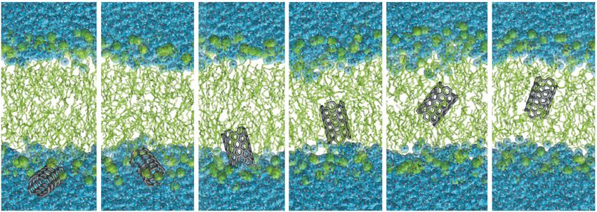
2 A.A. Tsukanov, S.G. Psakhie / Advanced Biomaterials and Devices in Medicine ! (2016) 19
between the nanotube and a polar solvent, which tends to lengths from 4.1 to 9.7 nm, both separately and within ag-
make the nanoparticles less hydrophobic. Moreover, in con- gregates, were considered. In the framework of our study
trast to CNT, BNNTs demonstrate a direct and indirect pie- we are interested in the case of short thin non-functionalized
zoelectric effect [28]. This provides BNNT with the possibi- CNT at the lower end of the range (diameter 1.23 nm, length
lity to change its electric properties and to generate electric 4.1 nm). The magnitude of the free energy barrier for such
signals, which may be controlled, for example, by external a CNT has an order of 110 kJ/mol, the maximum being at
ultrasonic waves [29]. Furthermore, despite the structural a distance of 3.54.5 nm from the bilayer center, depend-
similarity with CNT, BNNT is chirality-independent dielec- ing of the orientation of the nanotube (for pristine CNT
tric material with a wide band gap [30]. Due to these and with length 6.5 nm Baoukina et al. [41] have obtained
other properties, BNNT has been considered for many ap- Fbarr = 514 kJ/mol). The free energy minimum of about
plications, including nanovectors for intercellular drug and 300 kJ/mol is found near the membrane middle plane, and
gene delivery [3133], nanosensors and nanotransducers this value doesnt depend on the tubes orientation, due to
[34], contrast agents in neutron capture anticancer therapy the shortness of the penetrant.
[35], tissue engineering [36], and as nanofillers for compo- Kraszewski et al. [45] considered non-functionalized
site materials [37]. In addition, BNNT and CNT demon- CNT and CNTs with different number of amino-derivative
strate different selectivity to ion types that may pass through ligands on the surface. In particular, the free energy profile
the nanotube, and have therefore been suggested as artifi- for the insertion of pure capped (6, 6) single-walled CNT
cial ion channels potentially useful for numerous biomedi- into a POPC lipid membrane was evaluated. The CNT model
cal applications [38]. Experimental investigations of BNNT had 0.8 nm in diameter and a length of 5 nm. A free energy
with applications in nanomedicine are reviewed in [27]. An barrier of ~21 kJ/mol at the lipid/water interface and a lo-
overview of theoretical studies, fabrication methods, physi- cal minimum of 88 kJ/mol at 0.30.5 nm from the mem-
cal properties, chemical functionalization and applications brane center were observed.
of BNNTs can be found in [39]. Höfinger et al. [46] evaluated environmental free ener-
Unlike CNT, nanoscale mechanisms of BNNTs interac- gy landscapes for various orientations of single CNTs with
tion with biomolecules, proteins, cell membranes are mostly different lengths and CNT bundles of different size. For
unknown and poorly covered by computer simulations, in- this purpose, the membrane mimicry approach [47] was em-
cluding MD methods. To date, the only study that is touch- ployed there. For short single CNT, 0.8 nm in diameter and
ing on this bio-related direction is an investigation of the 2.1 nm in length, the free energy barrier is about 15 kJ/mol
stability and insertion mechanism of BNNT into the lipid and is located at ~2.9 nm from the bilayer center. The free
membrane, conducted by Thomas et al. using all-atom MD energy minimum at 0.01.1 nm from the bilayer center has
and SMD simulation [40]. The results obtained there indi- a depth ∆F ≈ 170 kJ/mol.
cate that (10, 0) armchair BNNT may spontaneously em- Gangupomu and Capaldi [48] used all-atom MD to com-
bed across the head group region of the lipids, which takes pute forces and the change in free energy during the penet-
about 100 ns from the initial position of 1.5 nm above mem- ration of a single-walled carbon nanotube (SWNT) into a
brane surface. It was also found that BNNTs remain in the pure POPC lipid bilayer and a POPC/cholesterol membrane.
lipophilic zone of the model POPC bilayer during the ex- The constant-velocity steered MD (cv-SMD) approach was
tended simulation time (about 200 ns). applied to calculate potential mean force (PMF) profiles.
The main aim of the present study is to compare the At the lowest pulling velocity (L = 1 nm/ns) the free energy
free energy difference ∆F and the magnitude of free energy barrier of perforation of the upper lipid monolayer by a
barrier Fbarr of insertion of BNNT into a lipid bilayer with CNT having 1 nm in diameter and 2 nm in length was esti-
those for CNT insertion. Short nanotubes were chosen to mated at about 150 kJ. This large value may be explained
avoid a multidimensionality of the problem, decreasing by irreversible disruption of the membrane due to the rela-
dependence on initial orientation of the penetrant. tively high velocity of the pulling process.
Pogodin and Baulin [49] estimated free energy change
during insertion of CNTs into a lipid bilayer using the single
2. Review of work on carbon nanotubes chain mean field theory [50]. A range of CNT diameters
In contrast to BNNT, the free energy of interaction be- from 1.00 to 4.86 nm, as well as different values of the
tween CNTs and lipid membranes was previously studied interaction parameter εT between CNT and the hydropho-
using MD. Baoukina et al. [41] conducted a broad study of bic core of the lipid bilayer were considered. Values from
the interaction of pristine and functionalized CNTs of dif- εT = 0 (steric repulsion) to εT = 6.3 kBT (strong hydropho-
ferent length, diameter, end termination and chemical modi- bicity) were used in the model. The free energy minimum
fication with a DOPC lipid bilayer. This study used coarse- for the case of highly hydrophobic thin CNTs having 1 nm
grained MD simulations based on the MARTINI force field in diameter was estimated at about 180 kJ/mol [49]. These
[4244]. Pristine CNTs and CNTs having hydrophilic results were obtained for perpendicularly constrained nano-
groups with diameters in the range of 1.232.40 nm and tubes of infinite length (more than the bilayer thickness).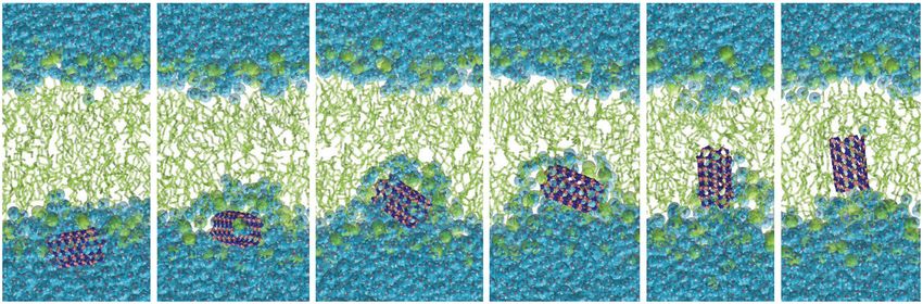
A.A. Tsukanov, S.G. Psakhie / Advanced Biomaterials and Devices in Medicine ! (2016) 19 3
Table 1. Comparison of estimates of free energy difference and barrier energy of intercalation of short and/or thin
pristine (non-functionalized) CNTs in cell membranes obtained using numerical simulations
∆F, kJ/mol Free energy minimum Fbarr, kJ/mol Barrier maximum
Study D, nm L, nm
(kcal/mol) position, nm (kcal/mol) position, nm
[41] 1.23 4.10 300 (72) ≈0.0 ~10 (2.5) 3.54.5
[45] 0.80 5.00 88 (21) 0.30.5 20.5 (4.9) 2.02.5
[46] 0.80 2.10 167 (40) 0.01.1 14.6 (3.5) ≈2.9
[48] 1.00 2.00 146 (35)
[49] 1.00 3.77* 180 (72.1kBT) 1.255** ≈0 ∞
(C60) [51] 0.70 0.70 92 (22) 0.60.7 ≈0 ∞
This study CNT 0.68 1.11 103 (25) 0.70.8 3.36.3 2.52.6
This study BNNT
0.69 1.13 72 (17) 0.71.0 020 2.12.3
Case 1, q ± 0.40 e
This study BNNT
0.69 1.13 11 (2.7) 2.42.6 105 (25) ≈0
Case 2, q ± 1.05 e
* Length of inserted part of the nanotube.
** Center of mass position of the inserted part of the nanotube.
Bold font marks values that are explicitly reported in the respective study.
Table 2. Models parameters of the numerical studies in this review
Chirality, open (O) / Model Base FF (if applicable) and Membrane
Study T, K Method
capped (C) level carbon LJ parameters model
[41] (CG), C CG MARTINI [4244] DOPC (648 pcs.) 310 US
CHARMM27-UA
POPC (180 pcs.)
[45] (6, 6), C AA/UA σ = 0.3895 nm [52] 300 ABF [53, 54]
0.649 nm2 per lipid
ε = 0.276 kJ/mol
AMBER
[46] (10, 0), C AA/MMA σ = 0.3400 nm MMA [47]
ε = 0.360 kJ/mol
CHARMM
cv-SMD
[48] (, ), O AA σ = not shown POPC (200 pcs.) 310
L = 1.00 nm/ns
ε = not shown
Minimization
SCMF in kBT
[49] Cylinder SCMF/CG DMPC of the free energy
εT = 6.3kBT (~301 K)
functional
CHARMM27
DMPC (52 pcs.) z-constrained
[51] C60 fullerene AA σ = 0.3895 nm [52] 310
0.618 nm2 per lipid MD
ε = 0.276 kJ/mol
CHARMM36-UA
POPC (104 pcs.) cv-SMD
[@]/CNT (5, 5), O AA/UA [55] σ = 0.3534 nm [56] 310
0.633 nm2 per lipid L = 0.05 nm/ns
ε = 0.2929 kJ/mol
POPC (104 pcs.) cv-SMD
[@]/BNNT1 (5, 5), O AA/UA CHARMM36-UA 310
0.632 nm2 per lipid L = 0.05 nm/ns
POPC (104 pcs.) cv-SMD
[@]/BNNT2 (5, 5), O AA/UA CHARMM36-UA 310
0.649 nm2 per lipid L = 0.05 nm/ns
[@]means this study, AAall-atom MD simulation, UAunited atom model (implicit hydrogen in acyl lipid chains), CGcoarse-
grained MD simulation, FFforce field, MMAmembrane mimicry approach [47], cv-SMDconstant velocity steered MD, SCMF
single chain mean field theory [50]. LJLennard-Jones parameters, USumbrella sampling [57], ABFadaptive biasing force
method [53, 54].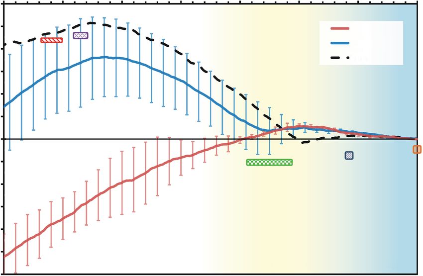
4 A.A. Tsukanov, S.G. Psakhie / Advanced Biomaterials and Devices in Medicine ! (2016) 19
120
Lipid tails Head groups Water
80
PMF(z) profiles, kJ/mol
40
0
40
CNT
80 BNNT set #1
BNNT set #2
120
0.0 0.5 1.0 1.5 2.0 2.5 3.0 3.5
Distance from the membrane center, nm
Fig. 1. PMF profiles versus distance of nanotube center of mass from bilayer center, cv-SMD result with L = 0.05 nm/ns. Blue curve
(5, 5) BNNT with partial charges ±0.4 e (set #1), redBNNT with charges ±1.05 e (set #2), dashed black line(5, 5) CNT. The red and
green rectangles approximately show, respectively, the local free energy minimum and the free energy barrier from results of [45]. The
purple rectangle is placed according to [51], the dark-blue square indicates the free energy barrier estimated in [46], the orange square
roughly indicates the energy barrier from [41]. Background shading: bluewater, yellowlipid head groups region, whitelipophilic
zone.
Obviously, the free energy profile would be different for blue and red curves correspond to two different sets of bo-
finite-length CNTs with rotational freedom. However, based ron nitride NTs and will be discussed further in the next.) A
on Pogodin and Baulin issues we could roughly define the rough estimate of the free energy minimum for (5, 5) CNT
position of the free energy minimum, assuming that the ∆FCNT: 103 kJ/mol, reached 0.70.8 nm from the bilayer
length of the inserted portion is a CNT length and that CNT center (Fig. 1, black dashed curve). Due to the short length
position is the position of the center of mass of the inserted of the considered CNT, its behavior should be very similar
fragment. Thus, the position of F minimum would be to that of fullerenes C60. If we compare our results with the
1.255 nm from the bilayer middle plane. results for C60 obtained by Bedrov et al. [51] (∆FC60 =
Summarizing the above review, we find that the free 92 kJ/mol, observed around 0.60.7 nm from the center),
energy of penetration of short and thin carbon nanotubes we find them in good agreement.
into cell membranes has been estimated to be 88300 kJ/mol Note also, that according to an approximate rule from
in magnitude, depending on size and orientation of the pen- [45], the free energy barrier of pristine capped CNT trans-
etrant (Table 1). The first free energy barrier varies from location into a lipid bilayer can be roughly estimated as
~10 to 21 kJ/mol, however, barrier-less insertion (Fbarr ~ ~1 kcal/mol per 1 nm of length and per 1 nm in diameter,
0) and large barriers of up to 150 kJ/mol have also been which in our case results in an estimation of Fbarr * ~
reported. The latter value corresponds to the energy required 1.11×0.68 kcal/mol ~ 3.2 kJ/mol, while in our simulation
to perforate a lipid monolayer (single leaflet), most likely this value is Fbarr ~ 3.3 kJ/mol from the initial free energy
in an irreversible process [48], which is why we do not take level or ~6.3 kJ/mol from the first local minimum observed
this study into account. The results mentioned in [41, 45, at the position 2.93.0 nm (Fig. 1, black dashed curve).
46, 48, 49] as well as our own results are presented in Thus, our estimation of the free energy profile for CNT
Table 1, the corresponding model parameters are summa- does not contradict any published data for similar condi-
rized in Table 2. tions. The obtained value of ∆F is in good agreement with
In the present study, in addition to our primary objec- results of [45, 51], the obtained magnitude of the barrier
tive, we simulated the translocation of a short (5, 5) carbon Fbarr is in between the results of [49, 51] and [41, 46] (see
SWNT into a lipid bilayer. A single 80 ns long SMD simu- Fig. 1). In the following, we will use the evaluated PMF
lation was performed. The results of PMF profile evalua- profile for CNT as a control line to compare the BNNT
tion are presented in Fig. 1 as a dashed black line. (The results with.A.A. Tsukanov, S.G. Psakhie / Advanced Biomaterials and Devices in Medicine ! (2016) 19 5
a
b
∆z, nm 2.0
1.0 0.4 0.0 0.4
0.5
30 50 62 70 78 80 t, ns
c
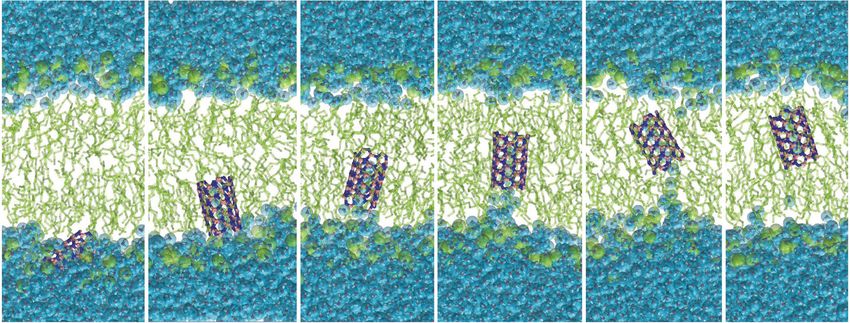
Fig. 2. Insertion of short (5, 5) nanotubes into a POPC lipid membrane during the pulling procedure of constant-velocity SMD simula-
tion: (a) CNT, no water observed inside the CNT when it is in the lipophilic bilayer region, (b) BNNT (case ±0.4 e), BNNT brings 4
5 water molecules inside, (c) BNNT (case ±1.05 e), in this case BNNT behavior is hydrophilic, the hydrated shell around nanotube
complicates the permeation into the lipophilic region of bilayer. Axes for time and ∆z are only for the snapshots in (b).
3. Boron nitride nanotubes: results and discussion charges of 0.4 e, whereas BNNT that contained 57 water
The partial atomic charges of BNNT are strongly envi- molecules inside, have a strong electric dipoles with ±1.05 e
ronmentally dependent, as was demonstrated in [58] by [58]. In the present study we have tested two BNNT mo-
using density functional theory (DFT). In particular, it was dels with both sets of partial charges.
shown that partial charges on boron and nitrogen atoms may SMD simulations with constant velocity (L = 0.05 nm/ns)
vary from ±0.37 e to ±1.05 e depending on both nanotube showed that BNNT (PAC set #1), unlike CNT, remain filled
radius and the presence of water molecules inside the nano- with 45 water molecules even in the hydrophobic core of
tube. In case of (5, 5) BNNT in vacuum, boron atoms had the lipid bilayer (Figs. 2a and 2b). Moreover, during the
partial charges of 0.4 e and nitrogen atoms had partial penetration of BNNT into the membrane, a water defect6 A.A. Tsukanov, S.G. Psakhie / Advanced Biomaterials and Devices in Medicine ! (2016) 19
was observed, which had the form of a several-water-mo- ter would demonstrate more hydrophobic behavior, and that
lecule long tail behind the penetrant until a depth z = 0.4 nm zigzag (5, 5) BNNTs are at least less cytotoxic than (5, 5)
(Fig. 2b, t = 78 ns). The PMF profile has a local minimum CNT.
10 ± 5 kJ/mol at the membrane surface in the region of A more accurate choice of partial charges or/and their
2.42.6 nm from the bilayer center (Fig. 1, blue curve). dependence on the environment will allow one to obtain
The magnitude of the free energy barrier reached at 2.1 more reliable results.
2.3 nm can be roughly estimated as 10.3 ± 8.6 kJ/mol, which
is not far from the CNT case. Moving through the lipid
head groups region, BNNT (both charge sets), like CNT, 4. Methods
tend to be oriented parallel to the membrane surface, while, The modeled systems were constructed using VMD
after the penetration into hydrophobic core of the bilayer, software [61] (http://www.ks.uiuc.edu/Research/vmd) and
the nanotubes predominantly have transmembrane ori- our own C/C++ functions library MoleSkola. Equilibration
entation and prefer to be parallel the lipid tails (Fig. 2). The and SMD simulations were performed with the LAMMPS
CNT and BNNT (set #1) PMF profiles are fairly similar, package (Sandia National Laboratory) [62, 63] (http://lammps.
the main difference being the depth of free energy well, sandia.gov/index.html). The united atoms CHARMM36-
which is 30% smaller for BNNT ∆FBNNT ≈ 72 kJ/mol UA force field [55] based on CHARMM36 FF [64] was
(Fig. 1). The presence of this deep local free energy mini- used for lipids. The membrane was composed of 104 POPC
mum inside the lipophilic bilayer region demonstrates the lipids, having implicit hydrogens in acyl chains. Water was
predominant hydrophobic behavior of the considered described with the TIP3P model [65]. The model of the
BNNT, which correlates with some experimental results of carbon (5, 5) SWNT was made in accordance with Kau-
wetting tests conducted in air [59, 60]. However, since the konen et al. [56]. Lennard-Jones parameters for NT carbon
penetrating single-walled BNNT, even with charges of atoms were σ = 0.3534 nm, ε = 0.2929 kJ/mol. Partial charges
±0.4 e, retain water molecules inside them during the trans- of NT carbon was zero. The CNT diameter and length were
location through the bilayer, we also have to look at the 0.68 nm and 1.11 nm, respectively. The modeled boron ni-
second case with partial charges ±1.05 e. tride SWNT was zigzag as well, having chirality (5, 5). The
The evaluated PMF profile for the BNNT model ha- BNNT had a diameter of 0.69 nm and a length of 1.13 nm.
ving PAC of ±1.05 e differs substantially from the first The Lennard-Jones parameters for B atoms were σ = 0.3453
BNNT case (Fig. 1). In this case the BN nanotube behaves nm, ε = 0.393 kJ/mol, and for NT nitrogen σ = 0.3365 nm,
as a hydrophilic nanoparticle and remains clothed in water ε = 0.602 kJ/mol, according to [38].
shell during the penetration process up to a distance z ≈ To describe BNNT electrostatics two different sets of
1 nm from the center of the membrane (Fig. 2c). The for- PACs were used according to estimations obtained with DFT
mation of such a stable water shell strongly hampers the calculations by Won and Aluru [58]: PAC set #1: QB = 0.4 e,
penetration of the nanotube into the hydrophobic core of QN = 0.4 e; set #2: QB = 1.05 e, QN = 1.05 e. The first set
the lipid bilayer. During the pulling process, the PMF is corresponds to (5, 5) BNNT in vacuum, the second to BNNT
increasing and reaches values of up to 105 ± 21 kJ/mol at filled with water molecules.
the membrane center (Fig. 1, red curve). This means that The equilibration of each system was conducted in NVT
BNNT (set #2) is not stable inside the cell membrane and (constant volume and temperature) conditions with human
that penetration is not energetically favorable, i.e. in this body temperature 310 K during 4 ns with 1 fs integration
case BN nanotubes do not spontaneously penetrate into and step. All constant velocity SMD simulations were performed
do not accumulate in the cell membrane. Therefore, BNNT in NPT thermo-barostat conditions [66]. Employing of the
with high partial charges would be less cytotoxic than the United Atom POPC lipid model and the SHAKE algorithm
pristine and even functionalized CNTs. Moreover, BNNT [67] for the remaining hydrogen atoms, allowed us to use a
(PAC set #2) has a quasi-stable configuration on the lipid- time step of τ = 2 fs. The entire system size was about
water interface, with PMF profile having a local minimum 20 thousand atoms, with initial simulation box dimensions
of 11 ± 3 kJ/mol at a distance of 2.42.6 nm from the mem- of 5.8×5.8×7.4 nm. The pairwise interaction cutoff was
brane midplane. 1.2 nm with 1.0 nm switching distance. Long-range elec-
The free energy estimations for the two BNNT models trostatics was computed using the PPPM algorithm [68]
with their respective sets of PACs gave greatly differing with a relative accuracy of 103.
results. However, it can be speculated that the free energy Free energy analysis was performed by potential of mean
change for the real system may be in between the PMF pro- force (PMF) calculations [69] employing steered MD simu-
files estimated for PAC set #1 and set #2. Additionally, in lation with a constant velocity L = 0.05 nm/ns. In each simu-
accordance with the study by Won and Aluru, the (5, 5) lation the initial position of the nanotube center of mass
BNNT filled with water has the largest partial charges was z = 3.5 nm, where z = 0 corresponds to the membrane
among zigzag BNNTs (n, n) with n = 5, 6, 9, 10 [58]. Based midplane. Total SMD simulation time was 290 ns for BNNT
on this, it can be concluded that BNNTs with a larger diame- set #1, 220 ns for set #2 and 80 ns for CNT.A.A. Tsukanov, S.G. Psakhie / Advanced Biomaterials and Devices in Medicine ! (2016) 19 7
5. Conclusions 5. Yang W, Thordarson P, Gooding JJ, Ringer SP, Braet F. Car-
bon nanotubes for biological and biomedical applications. Na-
In this study, the free energy difference and barrier ener-
notechnology. 2007; 18(41): 412001.
gy for the insertion of short boron nitride nanotubes into a
6. Liu Z, Tabakman S, Welsher K, Dai H. Carbon nanotubes in
cell membrane were calculated and compared with those biology and medicine: in vitro and in vivo detection, imaging
for equivalently sized carbon nanotube. Two sets of partial and drug delivery. Nano Research. 2009; 2(2): 85120.
atomic charges on boron and nitrogen atoms were consid- 7. Farmer VC, Fraser AR. Synthetic imogolite, a tubular hydroxy-
ered, resulting in BNNTs with a slightly hydrophobic or aluminium silicate. Developments Sedimentology. 1979; 27:
hydrophilic behavior. 547553.
The potential of mean force analysis showed that BNNT 8. Farmer VC, Smith BFL, Tait JM. The stability, free energy
with PAC of ±0.4 e has a 30% smaller depth of free energy and heat of formation of imogolite. Clay Miner. 1979; 14:
well than the equivalently sized CNT. Moreover, CNT re- 103107.
mained empty inside the lipid membrane whereas BNNT 9. Tenne R, Margulis L, Genut MEA, Hodes G. Polyhedral and
cylindrical structures of tungsten disulphide. Nature. 1992;
brings in several water molecules. The penetration BNNT
360(6403): 444446.
with PAC of ±1.05 e into the cell membrane is energeti- 10. Remskar M, Mrzel A, Skraba Z, Jesih A, Ceh M, Demar J, ...,
cally unfavorable, which indirectly indicates that in this case Mihailovic D. Self-assembly of subnanometer-diameter single-
BNNT would have a smaller impact on the cell membrane wall MoS2 nanotubes. Science. 2001; 292(5516): 479481.
and would be less cytotoxic than non-functionalized car- 11. Enyashin AN, Ivanovskii AL. Calculating the atomic and elec-
bon nanotubes and nanoparticles. tronic structure and magnetic properties of inorganic fulle-
It is important to note that the presented free energy renes. Russ J Phys Chem. 2005; 79(6): 940945.
values are still only rough estimation, due to the relatively 12. Rubio A, Corkill JL, Cohen ML. Theory of graphitic boron
high velocity of the pulling procedure we used, as well as nitride nanotubes. Phys Rev B. 1994; 49(7): 5081.
the limited accuracy of the partial atomic charges and their 13. Chopra NG, Luyken RJ, Cherrey K, Crespi VH, Cohen ML,
assumed independence from the environment in the classi- Louie SG, Zettl A. Boron nitride nanotubes. Science. 1995;
269(5226): 966967.
cal MD. For this reasons we regard our results as prelimi-
14. Badzian AR, Appenheimer S, Niemyski T, Olkusnik E. In:
nary and recommend repeating the calculations using a Glaski FA, editor. Third international conference on CVD,
lower velocity, or to perform sampling with long time ac- Salt Lake City, UT, 1972. Hindsdale, IL: Am. Nuclear Soc.;
cumulation. 1972.
The next logical step in modeling BNNT interaction with 15. Miyamoto Y, Rubio A, Cohen ML, Louie SG. Chiral tubules
biological materials, in particular cell membranes, would of hexagonal BC 2 N. Phys Rev B. 1994; 50(7): 4976.
be to incorporate some regularities of environment-induced 16. Miyamoto Y, Rubio A, Louie SG, Cohen ML. Electronic pro-
charge alteration using, for example, simplified quantum perties of tubule forms of hexagonal BC 3. Phys Rev B. 1994;
mechanics approaches. 50(24): 18360.
17. Xia X, Jelski DA, Bowser JR, George TF. MNDO study of
boron-nitrogen analogs of buckminsterfullerene. J Am Chem
Acknowledgments
Soc. 1992; 114(16): 64936496.
The authors thank Mikhail Popov (Berlin University of 18. Pokropivny VV, Skorokhod VV, Oleinik GS, Kurdyumov AV,
Technology, Germany) for useful discussions and help with Bartnitskaya TS, Pokropivny AV, ..., Sheichenko DM. Boron
the preparation of the publication. The present work was nitride analogs of fullerenes (the fulborenes), nanotubes, and
supported by the Russian Science Foundation (Grant fullerites (the fulborenites). J Solid State Chem. 2000; 154(1):
No. 14-23-00096). All reported MD simulations were per- 214222.
formed using cluster Lomonosov-1 of the Supercomputing 19. Sheichenko DM, Pokropivny AV, Pokropivny VV. Quantum-
chemistry calculation of B ~ nN ~ n-rings (n = 16) and fulbo-
Center (http://www.srcc.msu.su/nivc/index_engl.htm) of
renes, the fullerene-like molecules B ~ nN ~ n (n = 12, 24,
Lomonosov Moscow State University (MSU) [70].
60). Semiconductor Physics Quantum Electronics Optoelec-
tronics. 2000; 3(4): 545549.
References 20. Linnolahti M, Pakkanen TA. Molecular structures of alumina
1. Kroto HW, Heath JR, OBrien SC, Curl RF, Smalley RE. C60: nanoballs and nanotubes: A theoretical study. Inorg Chem.
Buckminsterfullerene. Nature. 1985; 318: 162163. 2004; 43(3): 11841189.
2. Iijima S. Helical microtubules of graphitic carbon. Nature. 21. Lee K, Mazare A, Schmuki P. One-dimensional titanium di-
1991; 354(6348): 5658. oxide nanomaterials: nanotubes. Chem Rev. 2014; 114(19):
3. Anilkumar P, Lu F, Cao LG, Luo P, Liu JH, Sahu S, et al. 93859454, and references therein.
Fullerenes for applications in biology and medicine. Current 22. Levi R, Bar-Sadan M, Albu-Yaron A, Popovitz-Biro R, Hou-
Medicinal Chem. 2011; 18(14): 20452059. ben L, Shahar C, Enyashin A, Seifert G, Prior Y, Tenne R.
4. Chen Z, Ma L, Liu Y, Chen C. Applications of functionalized Hollow V2O5 nanoparticles (fullerene-like analogues) pre-
fullerenes in tumor theranostics. Theranostics. 2012; 2(3): pared by laser ablation. J Am Chem Soc. 2010; 132(32):
238250. 11214.8 A.A. Tsukanov, S.G. Psakhie / Advanced Biomaterials and Devices in Medicine ! (2016) 19
23. Fagan SB, Baierle RJ, Mota R, da Silva AJ, Fazzio A. Ab 41. Baoukina S, Monticelli L, Tieleman DP. Interaction of pris-
initio calculations for a hypothetical material: Silicon nano- tine and functionalized carbon nanotubes with lipid mem-
tubes. Phys Rev B. 2000; 61(15): 9994. branes. J Phys Chem B. 2013; 117(40): 1211312123.
24. Pokropivny VV. Non-carbon nanotubes (Review). Part 1. Syn- 42. Marrink SJ, De Vries AH, Mark AE. Coarse grained model
thesis methods. Powder Metallurgy Metal Ceramics. 2001; for semiquantitative lipid simulations. J Phys Chem B. 2004;
40(9-10): 485496. 108(2): 750760.
25. Pokropivny VV. Non-carbon nanotubes (Review). Part 2. 43. Marrink SJ, Risselada HJ, Yefimov S, Tieleman DP, de
Types and structure. Powder Metallurgy Metal Ceramics. Vries AH. The MARTINI force field: coarse grained model
2001; 40(11-12): 582594. for biomolecular simulations. J Phys Chem B. 2007; 111(27):
26. Pokropivny VV. Non-carbon nanotubes (Review). Part 3. Pro- 78127824.
perties and applications. Powder Metallurgy Metal Ceramics. 44. Monticelli L. On atomistic and coarse-grained models for C60
2002; 41(3-4): 123135. fullerene. J Chem Theor Comp. 2012; 8(4): 13701378.
27. Genchi GG, Ciofani G. Bioapplications of boron nitride nano- 45. Kraszewski S, Bianco A, Tarek M, Ramseyer C. Insertion of
tubes. Nanomedicine. 2015; 10(22): 33153319. short amino-functionalized single-walled carbon nanotubes
28. Mele EJ, Král P. Electric polarization of heteropolar nanotubes into phospholipid bilayer occurs by passive diffusion. PLoS
as a geometric phase. Phys Rev Lett. 2002; 88(5): 056803. One. 2012; 7(7): e40703.
29. Ciofani G, Danti S, DAlessandro D et al. Enhancement of 46. Höfinger S, Melle-Franco M, Gallo T, Cantelli A, Calvaresi M,
neurite outgrowth in neuronal-like cells following boron ni- Gomes JA, Zerbetto F. A computational analysis of the inser-
tride nanotube-mediated stimulation. ACS Nano. 2010; 4: tion of carbon nanotubes into cellular membranes. Biomater.
62676277. 2011; 32(29): 70797085.
30. Lan HP, Ye LH, Zhang S, Peng LM. Transverse dielectric 47. Kar P, Seel M, Weidemann T, Höfinger S. Theoretical mimic-
properties of boron nitride nanotubes by ab initio electric field ry of biomembranes. FEBS Lett. 2009; 583(12): 19091915.
calculations. Appl Phys Lett. 2009; 94(18): 183110. 48. Gangupomu VK, Capaldi FM. Interactions of carbon nanotube
31. Chen X, Wu P, Rousseas M et al. Boron nitride nanotubes are with lipid bilayer membranes. J Nanomater. 2011; 2011:
noncytotoxic and can be functionalized for interaction with 830436.
proteins and cells. J Am Chem Soc. 2009; 131: 890891. 49. Pogodin S, Baulin VA. Can a carbon nanotube pierce through
32. Ferreira TH, Hollanda LM, Lancellotti M, de Sousa EMB. a phospholipid bilayer? ACS Nano. 2009; 4(9): 52935300.
Boron nitride nanotubes chemically functionalized with gly- 50. Pogodin S, Baulin VA. Coarse-grained models of phospho-
col chitosan for gene transfection in eukaryotic cell lines. J lipid membranes within the single chain mean field theory.
Biomed Mater Res A. 2015; 103: 21762185. Soft Matter. 2010; 6: 22162226.
33. Weng Q, Wang B, Wang X, Hanagata N, Li X, Liu D, Wang X, 51. Bedrov D, Smith GD, Davande H, Li L. Passive transport of
Jiang X, Bando Y, Golberg D. Highly water-soluble, porous, C60 fullerenes through a lipid membrane: a molecular dynam-
and biocompatible boron nitrides for anticancer drug deli- ics simulation study. J Phys Chem B. 2008; 112(7): 20782084.
very. ACS Nano. 2014; 8(6): 61236130. 52. Bedrov D, Smith GD, Li L. Molecular dynamics simulation
34. Danti S, Ciofani G, Moscato S et al. Boron nitride nanotubes study of the role of evenly spaced poly (ethylene oxide) te-
and primary human osteoblasts: in vitro compatibility and bio- thers on the aggregation of C60 fullerenes in water. Langmuir.
logical interactions under low frequency ultrasound stimula- 2005; 21(12): 52515255.
tion. Nanotechnology. 2013; 24: 465102. 53. Rodriguez-Gomez D, Darve E, Pohorille A. Assessing the ef-
35. Nakamura H, Koganei H, Miyoshi T, Sakurai T, Ono K, Suzu- ficiency of free energy calculation methods. J Chem Phys.
ki M. Antitumor effect of boron nitride nanotubes in combina- 2004; 120: 35633578.
tion with thermal neutron irradiation on BNCT. Bioorg Med 54. Darve E, Rodriguez-Gomez D, Pohorille A. Adaptive biasing
Chem Lett. 2015; 25: 172174. force method for scalar and vector free energy calculations. J
36. Lahiri D, Singh V, Benaduce AP, Seal S, Kos L, Agarwal A. Chem Phys. 2008; 128: 144120144113.
Boron nitride nanotube reinforced hydroxyapatite composite: 55. Lee S, Tran A, Allsopp M, Lim JB, Hénin J, Klauda JB.
mechanical and tribological performance and in-vitro biocom- CHARMM36 united atom chain model for lipids and surfac-
patibility to osteoblasts. J Mech Behav Biomed Mat. 2011; 4: tants. J Phys Chem B. 2014; 118(2): 547556.
4456. 56. Kaukonen M, Gulans A, Havu P, Kauppinen E. Lennard-Jones
37. Zhi CY, Bando Y, Tang CC, Honda S, Kuwahara H, Golberg D. parameters for small diameter carbon nanotubes and water for
Boron nitride nanotubes/polystyrene composites. J Mater Res. molecular mechanics simulations from van der Waals density
2006; 21(11): 27942800. functional calculations. J Comp Chem. 2012; 33(6): 652658.
38. Azamat J, Sardroodi JJ. The permeation of potassium and 57. Torrie GM, Valleau JP. Nonphysical sampling distributions
chloride ions through nanotubes: a molecular simulation study. in Monte Carlo free-energy estimation: Umbrella sampling. J
Monatshefte Chemie-Chemical Monthly. 2014; 145(6): 881 Comp Phys. 1977; 23(2): 187199.
890. 58. Won CY, Aluru NR. Structure and dynamics of water con-
39. Zhi C, Bando Y, Tang C, Golberg D. Boron nitride nanotubes. fined in a boron nitride nanotube. J Phys Chem C. 2008;
Mater Sci Eng R Rep. 2010; 70(3): 92111. 112(6): 18121818.
40. Thomas M, Enciso M, Hilder TA. Insertion mechanism and 59. Lee CH, Drelich J, Yap YK. Superhydrophobicity of boron
stability of boron nitride nanotubes in lipid bilayers. J Phys nitride nanotubes grown on silicon substrates. Langmuir. 2009;
Chem B. 2015; 119(15): 49294936. 25(9): 48534860.A.A. Tsukanov, S.G. Psakhie / Advanced Biomaterials and Devices in Medicine ! (2016) 19 9
60. Yum K, Yu MF. Measurement of wetting properties of indi- 67. Ryckaert JP, Ciccotti G, Berendsen HJ. Numerical integration
vidual boron nitride nanotubes with the Wilhelmy method of the cartesian equations of motion of a system with con-
using a nanotube-based force sensor. Nano Lett. 2006; 6(2): straints: molecular dynamics of n-alkanes. J Comp Phys. 1977;
329333. 23(3): 327341.
61. Humphrey W, Dalke A, Schulten K. VMD: visual molecular 68. Hockney RW, Eastwood JW. Computer simulation using par-
dynamics. J Mol Graphics. 1996; 14(1): 3338. ticles. Adam Hilger: New York; 1989.
62. Plimpton S. Fast parallel algorithms for short-range molecu- 69. Izrailev S, Stepaniants S, Isralewitz B, Kosztin D, Lu H,
lar dynamics. J Comp Phys. 1995; 117(1): 119. Molnar F, Wriggers W, Schulten K. Steered molecular dyna-
63. Plimpton S, Crozier P, Thompson A. LAMMPS-large-scale mics. In: Deuflhard P, Hermans J, Leimkuhler B, Mark AE,
atomic/molecular massively parallel simulator. Sandia Natl Reich S, Skeel RD, editors. Computational molecular dyna-
Lab. 2007; 18. mics: challenges, methods, ideas. Vol. 4 of lecture notes in
64. MacKerell AD, Bashford D, Bellott MLDR, Dunbrack RL, computational science and engineering. Berlin: Springer-
Evanseck JD, Field MJ, et al. All-atom empirical potential Verlag; 1998.
for molecular modeling and dynamics studies of proteins. J 70. Sadovnichy V, Tikhonravov A, Voevodin Vl, Opanasenko V.
Phys Chem B. 1998; 102(18): 35863616. Lomonosov: Supercomputing at Moscow State University.
65. Jorgensen WL, Chandrasekhar J, Madura JD, Impey RW, In: Contemporary high performance computing: From peta-
Klein ML. Comparison of simple potential functions for simu- scale toward exascale (Chapman & Hall/CRC Computational
lating liquid water. J Chem Phys. 1983; 79(2): 926935. Science). Boca Raton, USA: CRC Press; 2013.
66. Parrinello M, Rahman A. Polymorphic transitions in single
crystals: A new molecular dynamics method. J Appl Phys.
1981; 52(12): 71827190.You can also read


