Wide field of view and full Stokes polarization imaging using metasurfaces inspired by the stomatopod eye
←
→
Page content transcription
If your browser does not render page correctly, please read the page content below
Nanophotonics 2023; 12(6): 1137–1146

Research Article

Jianying Liu, Jinkui Chu*, Ran Zhang, Rui Liu and Jiaxin Fu

Wide field of view and full Stokes polarization
imaging using metasurfaces inspired
by the stomatopod eye
https://doi.org/10.1515/nanoph-2022-0712
Received November 14, 2022; accepted February 3, 2023;
 1 Introduction
published online February 24, 2023
 The compound eyes of stomatopods are a complex mul-
Abstract: Wide field of view and polarization imaging capa- tichannel optical system. Compared with traditional opti-
bilities are crucial for implementation of advanced imaging cal systems, it has the advantages of small size, large
devices. However, there are still great challenges in the inte- field of view, high time sensitivity and having polarized
gration of such optical systems. Here, we report a bionic vision [1–4]. Generally, the bionic compound eyes are
compound eye metasurface that can realize full Stokes designed as a planar microlens array or a curved microlens
polarization imaging in a wide field of view. The bionic com- array [5–10]. The disadvantage of planar microlens arrays
pound eye metasurface consists of a bifocal metalens array is the small field of view [11–13]. Although the curved
in which every three bifocal metalenses form a subeye. microlens array has a large field of view, the incompati-
The phase of the bifocal metalens is composed of gradient bility between the curved microlens array and the planar
phase and hyperbolic phase. Numerical simulations show detector leads to defocusing problem [14, 15]. The method of
that the bifocal metalens can not only improve the focusing gluing microlenses and photodetectors solves the alignment
efficiency in the oblique light but also correct the aberration problem between the focal points of the curved microlens
caused by the oblique incident light. And the field of view of array and the detectors, but the size of the bionic compound
the bionic compound eye metasurface can reach 120◦ × 120◦ . eyes made by this method is larger than that of the natural
We fabricated a bionic compound eye metasurface which compound eyes [16, 17]. In addition, the current research on
consists of three subeyes. Experiments show that the bionic the bionic compound eyes with large field of view neglects
compound eye metasurface can perform near diffraction- the polarized vision of the natural compound eyes.
limited polarization focusing and imaging in a large field of Metasurfaces have the ability to control the phase and
view. The design method is generic and can be used to design polarization of light in the subwavelength range and have
metasurfaces with different materials and wavelengths. It great potential for the integration of optical devices [18–21].
has great potential in the field of robot polarization vision For example, metasurfaces have been widely used to design
and polarization detection. metalens with polarization functions [22–25]. The research
 of polarization imaging based on dielectric metasurfaces
Keywords: bionic compound eye; full Stokes polarization
 mainly includes multispectral chirality imaging [26], Fourier
imaging; metasurfaces; wide field of view.
 matrix optics [27], and imaging polarimetry [28]. However,
 related studies on polarized imaging metasurfaces have the
 disadvantage of small field of view. The methods to elimi-
 nate the large field of view aberrations of dielectric meta-
 surfaces mainly include: using a double-layer metasurface
 to correct the aberrations [29]; designing metalens with fish-
*Corresponding author: Jinkui Chu, Key Laboratory for
Micro/Nano Technology and System of Liaoning Province, Dalian eye lens function [30]; relaxing the constraint on diffraction-
University of Technology, Dalian, China, E-mail: chujk@dlut.edu.cn. limited resolution [31]; using metalens arrays [32]. The com-
https://orcid.org/0000-0001-5742-8460 bination of gradient phase and hyperbolic phase has been
Jianying Liu, Ran Zhang, Rui Liu and Jiaxin Fu, Key Laboratory for demonstrated to be an effective method for increasing the
Micro/Nano Technology and System of Liaoning Province, Dalian Univer-
 field of view of metalenses for unpolarized light [32]. The
sity of Technology, Dalian, China. https://orcid.org/0000-0001-9256-4716
(J. Liu) disadvantage of these methods is that they are not compat-

 Open Access. © 2023 the author(s), published by De Gruyter. This work is licensed under the Creative Commons Attribution 4.0 International License.
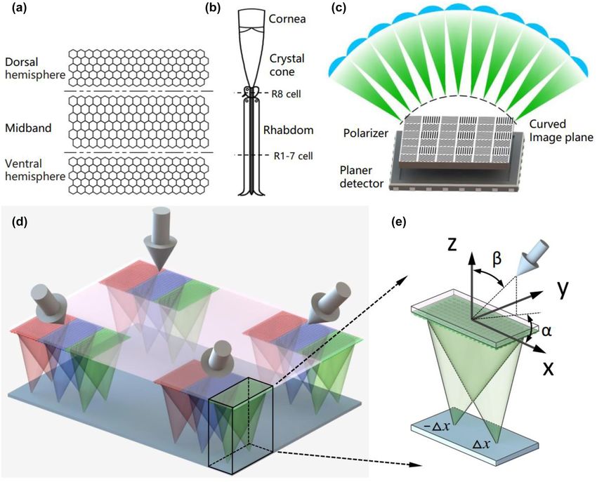
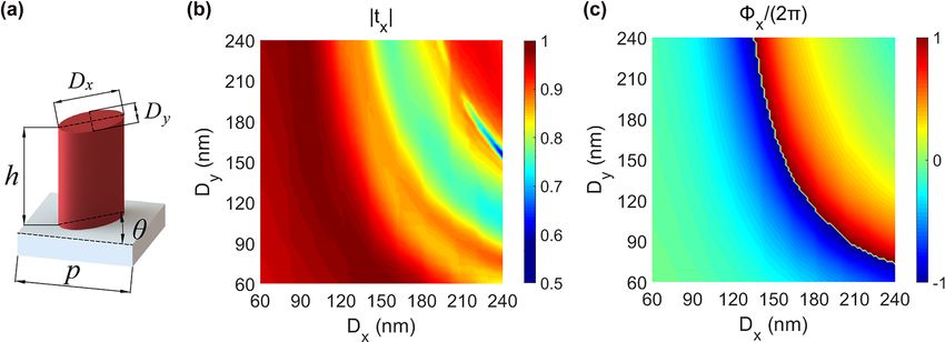
1138 — J. Liu et al.: Wide field of view and full Stokes polarization imaging using metasurfaces

ible with the design of polarized imaging metasurfaces. In Figure 1(d). The BCEM consists of a bifocal metalens array,
addition, related studies have shown that bifocal metalens where three bifocal metalens form a sub eye. The three
array with polarization multiplexing can be used to expand bifocal metalens that make up the sub eye are denoted by
the field of view [33, 34]. However, the metasurface still does the symbols X/Y, 45/135 and R/L, which decompose the inci-
not realize full Stokes polarization imaging in a large field dent light into X-LP and Y-LP (0◦ and 90◦ linearly polarized
of view. light), 45◦ -LP and 135◦ -LP (45◦ and 135◦ linearly polarized
 Inspired by the compound eyes of stomatopods, the light), RCP and LCP (right-handed and left-handed circularly
paper demonstrates a bionic compound eye metasurface polarized light).
(BCEM) with full Stokes polarization imaging in a large The azimuthal angle and elevation angle are used
field of view. The BCEM consists of a bifocal metalens array to describe the orientation of the sub eye visual axis, as
in which every three bifocal metalenses form a sub eye. shown in Figure 1(e). The coordinates of the sub eye in the
Each sub eye can decompose the incident light into two bionic compound eye metasurface are also represented by
pairs of linearly polarized light and one pair of circularly the azimuth and elevation angles, namely ( , ). The meta-
polarized light, and these are used to reconstruct the Stokes surface consists of a series of elliptical silicon pillars with
parameters. The orientation of the visual axis is different height h = 400 nm and period p = 300 nm, as shown in
for each sub eye, so the sub eye array can perform full Figure 2(a). We use the FDTD method to numerically simu-
Stokes polarization imaging of targets in different direc- late the effects of the major axis Dx and minor axis D y on
tions. The phase of the bifocal metalens is composed of gra- the phase shift and transmittance within a single period, as
dient phase and hyperbolic phase. The function of gradient shown in Figure 2(b) and (c).
phase and hyperbolic phase are to correct the light vector in In order to realize the function of simultaneous polar-
the oblique direction to the vertical direction and modulate ization imaging of targets in different directions with BCEM,
the wavefront of the light, respectively. The time-domain the phase of the bifocal metalens uses a combination of gra-
finite-difference (FDTD) method was used to numerically dient phase and hyperbolic phase, where the gradient phase
simulate the effect of gradient phase on the transmittance is used to correct the light vector in the oblique direction to
and focusing efficiency, and the ability to correct off-axis the vertical direction. If the azimuth and elevation angles of
aberration. We fabricated a BCEM consisting of three sub the sub eye visual axis are and , as shown in Figure 1(b).
eyes, and each sub eye has a different gradient phase. After Then the gradient phase of the sub eye can be described as:
characterizing the modulation transfer function (MTF) and √
 2 ( ) ( )2
focusing efficiency, etc. of the bifocal metalens in the sub ( , ) = sin (x cos( ))2 + y sin( ) (1)

eye, we experimentally achieved full Stokes polarization
imaging of the BCEM in a large field of view. where and are the azimuth and elevation angles, is the
 ( )√ ( )2
 wavelength of light, sin (x cos( ))2 + y sin( ) is the
 optical path difference between the oblique direction and
2 Design of BCEM the vertical direction of the light vector.
 The hyperbolic phase of the bifocal metalens is used
The compound eye of stomatopods (e.g., mantis shrimps) is to control the wavefront of light and focus it [37]. If the
a complex polarized optical system, which consists of six distance of the two focal points from the center of the bifocal
row of midband and dorsal and ventral hemispheres [35], metalens is ±Δx. Then the hyperbolic phase of the bifocal
and the distribution of ommatidium as shown in Figure 1(a). metalens satisfies:
Each ommatidium consists of cornea, crystal cone and (√ )
 2
rhabdom, as shown in Figure 1(b), where the retinal cells ±Δx = − (x ± Δx)2 + y2 + f 2 − f (2)
(R8) and (R1-7) are sensitive to polarized light. Currently, a
schematic diagram of the bionic compound eye with polar- where f is the focal length of the bifocal metalens.
ized vision is shown in Figure 1(c). The performance of The phase of the bifocal metalens is a combination
the bionic compound eye can be severely affected since of the gradient phase and hyperbolic phase, as shown in
the curved imaging plane is mismatched with the polar- Equation (3).
izer and the planar detector [2]. To solve the problem, we (√
 2
use metasurfaces instead of traditional microlens arrays to ( , )±Δx = − (x ± Δx)2 + y2 + f 2 − f
design the bionic compound eyes. In this paper, we propose
 √ )
a BCEM with full Stokes polarization imaging function in ( ) ( )2
 − sin (x cos( )) + y sin( )
 2
 (3)
a wide field of view, the schematic diagram is shown in
J. Liu et al.: Wide field of view and full Stokes polarization imaging using metasurfaces — 1139

Figure 1: Schemes of BCEM. (a) Schematic diagram of mantis shrimp’s ommatidium distribution. (b) Anatomical schematic of ommatidium in the
compound eye of mantis shrimp (adapted from [36]). (c) Schematic diagram of a bionic compound eye with polarized vision; there is a mismatch
between the curved image surface and the polarizer and planar detector. (d) Schematic diagram of the BCEM. (e) Schematic diagram of the bifocal
metalens in a sub eye, where and are the azimuth and elevation angles of the sub eye visual axis, respectively.

 [ [ ] [] ]
 It can be seen from Figure 2(b) and (c) that the phase ei x + ei y 1 ei x − ei y 1 −i2
 iΔ l
shift is continuous from 0 to 2π. The independent con- Elout =e + e (5)
 2 −i 2 i
trol of the orthogonal line polarization light by the bifocal
metalens can be achieved by selecting the suitable size of where, Erout and Elout are the right-handed and left-handed
the elliptical pillars [38]. Therefore, the parameters of the circularly polarization components of the emitted light,
X/Y and 45/135 bifocal metalenses can be calculated using respectively. eiΔ r and eiΔ l are the additional phases of the
Equation (3). The parameters of the R/L bifocal metalens orthogonal circular polarization components of the incident
are calculated using the improved PB phase method [38], as light. ei x and ei y are the phase shift of the elliptical pillars
shown in Equations (4) and (5). in the X and Y directions, respectively. is the rotation
 angle of the elliptical pillars. The elliptical pillar acting on
 [ [] [ ] ] circularly polarized light is regarded as a half-wave plate,
 ei x + ei y 1 ei x − ei y 1 i2
 Erout = eiΔ r + e (4) so Equations (4) and (5) also indicate that the chirality of the
 2 i 2 −i light is reversed by the bifocal metalens.
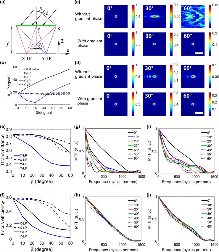
1140 — J. Liu et al.: Wide field of view and full Stokes polarization imaging using metasurfaces

Figure 2: Design of the metasurface. (a) Schematic diagram of the elliptical silicon pillar, the substrate is silica. (b) and (c) Calculated transmittance
and phase shift of a single period for X-LP normal incident light with a wavelength of 780 nm.

3 Numerical simulation and off-axis angle constant at oblique incident light and reduce
 the aberration of the bifocal metalens. In addition, the con-
 performance of bifocal metalens stant off-axis angle avoids light crosstalk from the adjacent
 bifocal metalenses with different visual axes. This charac-
Taking X/Y bifocal metalens as an example, we use the FDTD teristic of the gradient phase is used to design the BCEM with
method to simulate the correction of off-axis aberration by a large field of view.
the gradient phase. The size of the bifocal metalens is 15 × We also simulated the transmittance and focusing effi-
30 μm, and the focal length is 24.2 μm. In the paper, the angle ciency of the two bifocal metalenses, as shown in Figure 3(e)
corresponding to the distance from the spot position to the and (f). It can be seen from these figures that the bifocal
center of the bifocal metalens is defined as the off-axis angle, metalens with gradient phase has higher transmittance and
as shown in Figure 3(a). In the simulation, the azimuth angle focusing efficiency when the elevation angle increases. The
is 0◦ , the elevation angle is changed from 0◦ to 60◦ , and X-directional MTF of the bifocal metalens is the Fourier
the incident light is linearly polarized light (X-LP and Y-LP). transform of the X-directional line spread function (LSF).
The 1 and 2 in Figure 3(a) are the off-axis angles of the Figure 3(g), (h) and (i), (j) show the MTFs of the X-LP and
X-LP and Y-LP components, respectively. For a traditional Y-LP components in the X-direction for the two bifocal met-
bifocal metalens, the two focal points in Figure 3(a) shift alenses, respectively. It can be seen from these figures that
to the left as the elevation angle increases. The curves the MTFs of the bifocal metalens with gradient phasing is
of off-axis angles 1 and 2 with the elevation angle are higher than that of the traditional bifocal metalens when the
shown as solid lines in Figure 3(b). For the bifocal metal- elevation angle increases. Therefore, the same conclusion as
ens with gradient phase, the azimuth and elevation angles in the previous paragraph can be deduced that the gradient
of metalens are equal to the angle of the incident light. phase can reduce the aberration caused by oblique incident
Thus the gradient phase compensates the optical path dif- light.
ference caused by the oblique light, and the off-axis angles
of the two focal points remain near their initial values, as
shown by the dashed lines in Figure 3(b). Figure 3(c) and (d)
show the focused spots of the X-LP and Y-LP components
 4 Characterization and polarization
of the two bifocal metalenses at different elevation angles, imaging performance of BCEM
respectively. It can be seen from Figure 3(b)–(d) that the
aberration of traditional bifocals increases with the off-axis We fabricated a BCEM with three sub eyes whose coordi-
angle increases, which will reduce the imaging resolution. nates are (0,0), (0,30), and (90,30), respectively. The size of
However, the off-axis angle and aberration of the bifocal the sub eye is 120 × 180 μm, and the focal length is 340 μm.
metalens with gradient phase are almost unchanged. Thus, To reduce the effect of stray light on the experiment, we
it can be concluded that the gradient phase can keep the fabricated 200 nm chromium (Cr) around the sub eyes as
J. Liu et al.: Wide field of view and full Stokes polarization imaging using metasurfaces — 1141

Figure 3: Theoretical analysis and numerical simulation of the metalens. (a) Schematic diagram of the optical path of the bifocal metalens in the XOZ
plane, where 1 and 2 are the off-axis angles of the X-LP and Y-LP components, respectively. The line cd represents the optical path difference
between the oblique light vector and the vertical light vector on the bifocal metalens. (b) When = 0, the off-axis angles of the X-LP and Y-LP
components in (a), where the solid and dashed lines represent the traditional bifocal metalens and the bifocal metalens with gradient phase,
respectively, and the dotted line represents the initial value. (c) and (d) When = 0, the focused spots of X-LP and Y-LP components of the two bifocal
metalenses at different elevation angles, respectively. Scale bar: 3 μm. (e) and (f) When = 0, the transmittance and focusing efficiency of the two
bifocal metalenses, the solid and dashed lines represent the traditional bifocal metalens and the bifocal metalens with gradient phase, respectively. (g)
and (h) MTFs of the X-LP components at different elevation angles for the traditional bifocal metalens and the bifocal metalens with gradient phase,
respectively. (i) and (j) MTFs of the Y-LP components at different elevation angles for the traditional bifocal metalens and the bifocal metalens with
gradient phase, respectively.
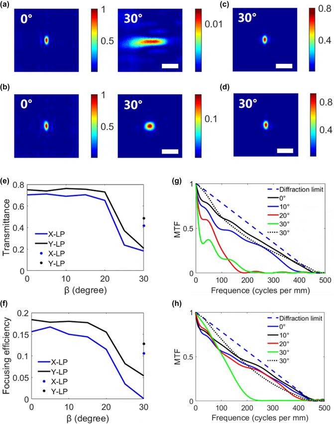
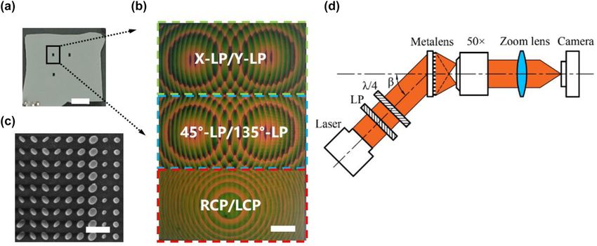
1142 — J. Liu et al.: Wide field of view and full Stokes polarization imaging using metasurfaces

a light shielding film, and its fabrication process in Supple- The measurements of the focused spot for the X/Y bifo-
mentary Materials Section 2. Photograph of the BCEM sam- cal metalenses located at (0,0) and (0,30) are shown in
ple is shown in Figure 4(a), and its microscope and scanning Figure 5(a)–(d). Figure 5(a) and (b) show the focused spots
electron microscope (SEM) images are shown in Figure 4(b) of the X-LP and Y-LP components of the bifocal metalens
and 4(c), respectively. located at (0,0), respectively. As can be seen from Figure 3(b),
 The schematic diagram of the polarization focusing the off-axis angle of the X-LP component is larger than
experiment of the BCEM is shown in Figure 4(d). A col- that of the Y-LP component when = 30◦ . Similar to the
limated laser (Fulei, China, FU780AD100-PXG2698-20) with simulated results, the aberration of the X-LP component
a wavelength of 780 nm is used as the light source, and is larger than that of the Y-LP component for the bifocal
the laser is passed through a linear polarizer (Codixx, Ger- metalens located at (0,0) when = 30◦ . Figure 5(c) and (d)
many, MPF10-600-10,000) and a quarter-wave plate (THOR- show the focused spots of the X-LP and Y-LP components
LABS, AQWP05M-580) to form polarized light with a spe- of the bifocal metalens located at (0,30), respectively. Com-
cific polarization state. Then, a 50× objective lens (Mitu- pared with Figure 5(a) and (b), Figure 5(c) and (d) show
toyo, M Plan Apo 50X/0.55), a zoom lens (navitar-1 6010) the correction of off-axis aberration caused by oblique
and a camera (Sony, Basler acA4024-29um) were used to incident light corrected for the bifocal metalens located
magnify the image formed by the BCEM. The angle between at (0,30).
the direction of the light source and the metasurface is , Figure 5(e) and (f) show the experimental results of
which is equal to the elevation angle of the sub eye in the transmittance and focusing efficiency of the X/Y bifocal met-
experiment. alenses located at (0,0) and (0,30), respectively. The MTFs
 It can be known from the previous section that the sub are the Fourier transforms of the LSFs in the X-direction, as
eye located at (0,0) acts on the normal incident light with shown in Figure 5(g) and (h). That is, the gradient phase not
a value of zero for the gradient phase. Therefore, the test only improves the transmission and focusing efficiency of
results of this sub eye in oblique light can be used for the X/Y bifocal metalens in large fields of view, but also corrects
comparison data of the other two sub eyes. First we tested the aberration caused by oblique incident light.
the polarization focusing performance of the X/Y bifocal The imaging performance of the BCEM was tested using
metalenses in the sub eyes and calculated the corresponding six stripes similar to the USAF resolution test chart, and
MTFs, where the light source was set to linearly polarized the experimental optical path is shown in Figure 6(a). The
light (X-LP and Y-LP). light source uses LEDs with a wavelength of 780 nm, and

Figure 4: Manufactured BCEM sample and its test optical path. (a) Photograph of the BCEM sample. Scale bar: 1 mm. (b) Microscopic image of the sub
eye, which consists of three bifocal metalenses. Three bifocal metalenses decompose the light into X-LP and Y-LP, 45◦ -LP and 135◦ -LP, RCP, and LCP,
respectively. Scale bar: 20 μm. (c) SEM image of the bionic compound eye metasurface. Scale bar: 600 nm. (d) Schematic diagram of the optical path
for testing the focusing performance of the BCEM. Where LP and λ/4 denote line polarizer and quarter-wave plate.
J. Liu et al.: Wide field of view and full Stokes polarization imaging using metasurfaces — 1143

Figure 5: Experiment of polarization focusing by the metalens. (a) and (b) The focused spot of the X-LP and Y-LP components of the bifocal metalens
located at (0,0), respectively. (c) and (d) The focused spot of the X-LP and Y-LP components of the bifocal metalens located at (0,30), respectively. The
angle in (a)–(d) is the value of in the experiment. Scale bar 10 μm. (e) and (f) Transmittance and focusing efficiency of the X/Y bifocal metalenses. The
solid line and dots represent the X/Y bifocal metalens located at (0,0) and (0,30), respectively. (g) and (h) MTFs of X-LP and Y-LP components of the X/Y
bifocal metalenses, where the solid and dashed lines represent the X/Y bifocal metalens located at (0,0) and (0,30), respectively, and the dashed line
represents the diffraction limit.
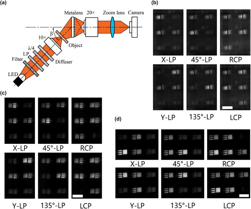
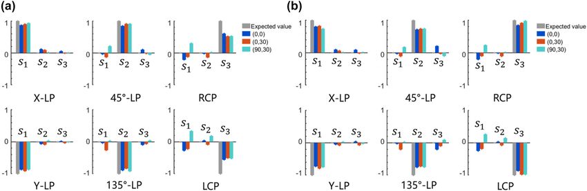
1144 — J. Liu et al.: Wide field of view and full Stokes polarization imaging using metasurfaces

Figure 6: Experiment of polarization imaging by the BCEM. (a) Schematic diagram of the optical path used to test the imaging performance of the
BCEM. (b)–(d) Full Stokes polarization imaging tests of sub eyes located at (0,0), (0,30), and (90,30), respectively. The results in (d) were tested with the
BCEM rotated 90◦ counterclockwise.

the light is transformed into uniformly polarized light after light image is smaller than that of the linearly polarized light
passing through a filter (Hengyang Optics, China, HNIF-010- image. In addition, the image of the polarization compo-
780-H-D25), a linear polarizer, a quarter-wave plate and a nent orthogonal to the polarization state of the light source
diffuser (C.F.Technology, China, DG10-1500). A 10× objective is also slightly visible. We think that the imperfection of
lens (Mitutoyo, M Plan Apo 10X/0.28) was used to focus light the test results is due to the manufacturing error of the
onto the resolution test chart, and then a 20× objective metasurface. Theoretically, the size of the elliptical pillar
lens (Mitutoyo, M Plan Apo 20X/0.42), a zoom lens, and determines the phase shift and transmittance of the light,
a camera were used to record the imaging of the BCEM. which further determines the independent control of the
Figure 6(b) and (c) show the imaging tests of the sub eyes polarization component by the bifocal metalens. Therefore,
located at (0,0) and (0,30) with different polarized light, the fabrication error of the metasurface is the main reason
respectively. Due to the limitation of the two-dimensional to affect its performance. To demonstrate the polarization
experimental platform, the BCEM was rotated 90◦ counter- information of the images obtained by BCEM in more detail,
clockwise before testing for the sub eye located at (90,30), we extracted the Stokes parameters from the Figure 6(b)
and results are shown in Figure 6(d). It can be seen from and (c), as shown in Figure 7(a) and (b) (method as in Sup-
Figure 6(b)–(d) that the intensity of the circularly polarized plementary Section 1). It is known from Figure 7(a) that the
J. Liu et al.: Wide field of view and full Stokes polarization imaging using metasurfaces — 1145

Figure 7: Characterization results of polarization imaging by the BCEM. (a) Stokes parameter reconstruction results of Figure 6(b)–(d). (b) Stokes
parameter reconstruction results after normalizing the image intensity of Figure 6(b)–(d). Where gray, blue, red, and cyan bars represent the expected
values, and experimental results of sub eyes located at (0,0), (0,30), and (90,30), respectively.

accuracy of the Stokes parameter reconstruction for linearly addition, the BCEM realizes the integrated design of lens
polarized light is higher than that for circularly polarized and polarization device, which makes the bionic compound
light by the three subeyes. For the reason that the intensity eye smaller in size and more integrated. The BCEM has
of the linearly polarized light image is larger than that of the great potential for endoscopy, industrial inspection, remote
circularly polarized light image. The reconstruction accu- sensing, and underwater detection.
racy of circularly polarized light can be improved by nor-
malizing the image intensity of the three bifocal metalenses Author contributions: All the authors have accepted
in the sub eye (method as in Supplementary Section 1), as responsibility for the entire content of this submitted
shown in Figure 7(b). Therefore, the full Stokes polarization manuscript and approved submission.
imaging capability of the BCEM in a wide field of view was Research funding: None declared.
demonstrated experimentally. Conflict of interest statement: The authors declare no con-
 flicts of interest regarding this article.

5 Conclusions References
In summary, we propose a BCEM that achieved full Stokes
 [1] H. H. Thoen, M. J. How, T. Chiou, and J. Marshall, “A different form
polarization imaging in a wide field of view. Similar to the of color vision in Mantis shrimp,” Science, vol. 343, no. 6169,
natural compound eye, the BCEM consists of an array of pp. 411 − 413, 2014..
sub eyes, and the orientation of the visual axis is different [2] Z. Hu, Y. Zhang, C. Pan, et al., “Miniature optoelectronic compound
for each sub eye. Each sub eye consists of three bifocal eyecamera,” Nat. Commun., vol. 13, no. 1, pp. 1 − 10, 2022..
 [3] M. Garcia, C. Edmiston, R. Marinov, A. Vail, and V. Gruev,
metalenses which can achieve full Stokes polarization imag-
 “Bio-inspired color-polarization imager for real-time in situ
ing for the target. Since the sub eyes located at different imaging,” Optica, vol. 4, no. 10, p. 1263, 2017..
coordinates have different gradient phases, the BCEM can [4] I. M. Daly, M. J. How, J. C. Partridge, et al., “Dynamic polarization
perform simultaneous full Stokes polarization imaging of vision in mantis shrimps,” Nat. Commun., vol. 7, no. 1, pp. 1 − 9,
targets in a wide field of view. The gradient phase improves 2016..
the transmittance and focusing efficiency of the bifocal [5] Y. Cheng, J. Cao, Y. Zhang, and Q. Hao, “Review of state-of-the-art
 artificial compound eye imaging systems,” Bioinspiration
metalens at oblique incident light, as well as reduces the
 Biomimetics, vol. 14, no. 3, p. 31002, 2019..
aberration caused by oblique incident light. Compared with [6] S. Wu, T. Jiang, G. Zhang, et al., “Artificial compound eye: a survey
the curved microlens array, the imaging plane of the BCEM of the state-of-the-art,” Artif. Intell. Rev., vol. 48, no. 4,
can be completely coincident with the planar detector. In pp. 573 − 603, 2017..
1146 — J. Liu et al.: Wide field of view and full Stokes polarization imaging using metasurfaces

 [7] J. Liu, R. Zhang, Y. Li, et al., “A bio-inspired polarization navigation [23] A. Arbabi, Y. Horie, M. Bagheri, and A. Faraon, “Dielectric
 sensor based on artificial compound eyes,” Bioinspiration metasurfaces for complete control of phase and polarization with
 Biomimetics, vol. 17, no. 4, pp. 1 − 10, 2022.. subwavelength spatial resolution and high transmission,” Nat.
 [8] W. Kuo, S. Lin, S. Hsu, and H. H. Yu, “Fabrication and investigation Nanotechnol., vol. 10, no. 11, pp. 937 − 943, 2015..
 of the bionic curved visual microlens array films,” Opt. Mater., [24] Z. Yang, Z. Wang, Y. Wang, et al., “Generalized Hartmann-Shack
 vol. 66, pp. 630 − 639, 2017.. array of dielectric metalens sub-arrays for polarimetric beam
 [9] C. Shi, Y. Wang, C. Liu, et al., “SCECam: a spherical compound eye profiling,” Nat. Commun., vol. 9, no. 1, pp. 1 − 7, 2018..
 camera for fast location and recognition of objects at a large field [25] H. Liang, Q. Lin, X. Xie, et al., “Ultrahigh numerical aperture
 of view,” Opt. Express, vol. 25, no. 26, p. 32333, 2017.. metalens at visible wavelengths,” Nano Lett., vol. 18, no. 7,
[10] H. Bian, Y. Wei, Q. Yang, et al., “Direct fabrication of pp. 4460 − 4466, 2018..
 compound-eye microlens array on curved surfaces by a facile [26] M. Khorasaninejad, W. T. Chen, A. Y. Zhu, et al., “Multispectral
 femtosecond laser enhanced wet etching process,” Appl. Phys. chiral imaging with a metalens,” Nano Lett., vol. 16, no. 7,
 Lett., vol. 109, no. 22, p. 221109, 2016.. pp. 4595 − 4600, 2016..
 [11] A. Bruckner, J. Duparre, R. Leitel, P. Dannberg, A. Brauer, and [27] N. A. Rubin, G. D Aversa, P. Chevalier, Z. Shi, W. T. Chen, and
 A. Tunnermann, “Thin wafer-level camera lenses inspired by insect F. Capasso, “Matrix Fourier optics enables a compact full-Stokes
 compound eyes,” Opt. Express, vol. 18, no. 24, pp. 24379 − 24394, polarization camera,” Science, vol. 365, p. 6448, 2019..
 2010.. [28] E. Arbabi, S. M. Kamali, A. Arbabi, and A. Faraon, “Full-Stokes
[12] K. Stollberg, A. Bruckner, J. Duparre, P. Dannberg, A. Brauer, and imaging polarimetry using dielectric metasurfaces,” ACS Photonics,
 A. Tunnermann, “The Gabor superlens as an alternative vol. 5, no. 8, pp. 3132 − 3140, 2018..
 wafer-level camera approach inspired by superposition compound [29] A. Arbabi, E. Arbabi, S. M. Kamali, Y. Horie, S. Han, and A. Faraon,
 eyes of nocturnal insects,” Opt. Express, vol. 17, no. 18, “Miniature optical planar camera based on a wide-angle
 pp. 15747 − 15759, 2009.. metasurface doublet corrected for monochromatic aberrations,”
[13] J. Duparré, P. Dannberg, P. Schreiber, A. Bräuer, and Nat. Commun., vol. 7, no. 1, pp. 1 − 9, 2016..
 A. Tünnermann, “Thin compound-eye camera,” Appl. Opt., vol. 44, [30] M. Y. Shalaginov, S. An, F. Yang, et al., “Single-element
 no. 15, p. 2949, 2005.. diffraction-limited fisheye metalens,” Nano Lett., vol. 20, no. 10,
[14] H. Liu, F. Chen, Q. Yang, et al., “Fabrication of bioinspired pp. 7429 − 7437, 2020..
 omnidirectional and gapless microlens array for wide field-of-view [31] A. Martins, K. Li, J. Li, et al., “On metalenses with arbitrarily
 detections,” Appl. Phys. Lett., vol. 100, no. 13, p. 133701, 2012.. wide field of view,” ACS Photonics, vol. 7, no. 8, pp. 2073 − 2079,
[15] Y. Cherng and G. J. Su, “Fabrication of polydimethylsiloxane 2020..
 microlens array on spherical surface using multi-replication [32] J. Chen, X. Ye, S. Gao, et al., “Planar wide-angle-imaging
 process,” J. Micromech. Microeng., vol. 24, no. 1, p. 15016, 2014.. camera enabled by metalens array,” Optica, vol. 9, no. 4, p. 431,
[16] D. Floreano, R. Pericet-Camara, S. Viollet, et al., “Miniature curved 2022..
 artificial compound eyes,” Proc. Natl. Acad. Sci., vol. 110, no. 23, [33] B. Xu, H. Li, S. Gao, et al., “Metalens-integrated compact imaging
 pp. 9267 − 9272, 2013.. devices for wide-field microscopy,” Adv. Photonics, vol. 2, no. 6,
 [17] Y. M. Song, Y. Xie, V. Malyarchuk, et al., “Digital cameras with p. 66004, 2020..
 designs inspired by the arthropod eye,” Nature, vol. 497, no. 7447, [34] X. Ye, X. Qian, Y. Chen, et al., “Chip-scale metalens microscope for
 pp. 95 − 99, 2013.. wide-field and depth-of-field imaging,” Adv. Photonics, vol. 4, no. 4,
[18] Y. Hu, X. Wang, X. Luo, et al., “All-dielectric metasurfaces for p. 46006, 2022..
 polarization manipulation: principles and emerging applications,” [35] J. Marshall, T. W. Cronin, and S. Kleinlogel, “Stomatopod eye
 Nanophotonics, vol. 9, no. 12, pp. 3755 − 3780, 2020.. structure and function: a review,” Arthropod Struct. Dev., vol. 36,
[19] X. Luo, Y. Hu, X. Li, et al., “Integrated metasurfaces with no. 4, pp. 420 − 448, 2007..
 microprints and helicity-multiplexed holograms for real-time [36] G. Horvath, S. Collin, and J. Marshall, Polarized Light and
 optical encryption,” Adv. Opt. Mater., vol. 8, no. 8, p. 1902020, Polarization Vision in Animal Sciences, vol. 2, Berlin, Springer, 2014.
 2020.. [37] F. Aieta, P. Genevet, M. A. Kats, et al., “Aberration-free ultrathin
[20] S. Zhang, C. L. Wong, S. Zeng, et al., “Metasurfaces for biomedical flat lenses and axicons at telecom wavelengths based on
 applications: imaging and sensing from a nanophotonics plasmonic metasurfaces,” Nano Lett., vol. 12, no. 9,
 perspective,” Nanophotonics, vol. 10, no. 1, pp. 259 − 293, 2020.. pp. 4932 − 4936, 2012..
[21] Q. Ma, Q. R. Hong, X. X. Gao, et al., “Smart sensing metasurface [38] J. Liu, R. Zhang, Y. Fan, H. Cheng, C. Guan, and J. Chu, “A novel
 with self-defined functions in dual polarizations,” Nanophotonics, method for the design of a full Stokes polarimeter based on
 vol. 9, no. 10, pp. 3271 − 3278, 2020.. dielectric metasurfaces,” Optik, vol. 261, p. 169198, 2022..
[22] R. Chen, Y. Zhou, W. Chen, R. Chen, N. Iqbal, and Y. Ma,
 “Multifunctional metasurface: coplanar embedded design for
 metalens and nanoprinted display,” ACS Photonics, vol. 7, no. 5, Supplementary Material: This article contains supplementary material
 pp. 1171 − 1177, 2020.. (https://doi.org/10.1515/nanoph-2022-0712).
You can also read