Wide angle broadband antireflection coatings based on boomerang like alumina nanostructures in visible region - Nature
←
→
Page content transcription
If your browser does not render page correctly, please read the page content below
www.nature.com/scientificreports
OPEN Wide‑angle broadband
antireflection coatings based
on boomerang‑like alumina
nanostructures in visible region
MirKazem Omrani*, Mohammad Malekmohammad* & Hosein Zabolian
A novel boomerang-like alumina based antireflective coating with ultra-low reflectance has been
produced for light incidence angles form 0 up to 45°. Boomerang-like alumina nanostructures have
been fabricated on the BK7 glass substrates by dip-coating and surface modification via hot water
treatment. To achieve the lowest residual reflectance, the effect of dip-coating rate and hot-water
temperature in the treatment process has been investigated and optimized. To further investigate the
boomerang-like alumina nanostructure and extract its graded refractive index profile by fitting the
measured reflectance spectrum with the simulated one, a simulation based on the finite-difference
time-domain (FDTD) method has been performed. The average reflectance measured at normal
incidence for double-sided coated BK7 glass substrates is only 0.3% in the visible spectral region.
Considering both sides, the average reflectance of the substrate decreased in the spectral range
of 400–700 nm down to 0.4% at incidence angles of 45° by applying the boomerang-like alumina
antireflection coatings. The optimized single layer boomerang-like alumina coating on the curved
aspheric lens exhibited a low average reflectance of less than 0.14% and an average transmittance of
above 99.3% at normal incidence. The presented process is a simple and cost-effective route towards
broadband and omnidirectional antireflection coatings, which have promising potential to be applied
on substrates having large scales with complex geometric shapes.
The reflections of light that occurs at the interface between air and materials, due to the sharp change of refrac-
tive indices, must be eliminated in advanced optical systems to increase performance and reduce ghost images
and flare. As a result, a single-layer anti-reflective
√ coating must have a refractive index equal to the square root
value of the substrate refractive index (ncoat = nsub ) to achieve zero reflection, where the optical thickness of
the anti-reflective layer is a quarter of the wavelength (ncoat × d = 4 , where d is the physical thickness)1,2. For
instance, an anti-reflective coating with a refractive index of less than 1.25 is required for fused silica substrates.
Since there is no known material with this refractive index, only sub-wavelength nanoporous nanostructures,
which are solid materials having air pores, can fulfill this requirement. However, in the case of meeting the above
conditions, a zero reflectance is achieved solely at a specified wavelength due to the uniformity of the effective
refractive index along the coating thickness. To achieve a broadband anti-reflective coating, the key issue is to
avoid sharp changes in the effective refractive index between the air and the substrate. The refractive index of
the coating should gradually increase from the coating surface to the interface. For this purpose, multilayer coat-
ings have been developed in which the optical thickness of each layer is at least one-quarter of the wavelength
and the refractive index of the layers from top to bottom should be incremental. According to optical theory,
the refractive index of a multilayer stack must satisfy the equation: nn1s = nn21 = · · · = nna , where ns and na are the
k
reflective indices of the substrate and of air, r espectively3.
On the other hand, modern optical systems are often based on lenses with different radii of curvature, and
the incoming light impinges on the lens surface under various incidence angles. Therefore, providing an omni-
directional anti-reflective coating is of considerable importance. So far, the multifunctional broadband anti-
reflective coatings are commonly prepared by physical vapor deposition (PVD) and chemical vapor deposition
(CVD) techniques such as plasma-enhanced CVD, sputtering and e vaporation4–6. However, thickness gradients
can occur on curved substrate surfaces due to shadowing effects. Due to changes in film thickness, the coat-
ing in steep inclinations of the substrate surface does not meet the desired specification and leads to increased
Department of Physics, University of Isfahan, P.O. Box 81746‑7344, Isfahan, Iran. *email: kazem.omrani@semnan.
ac.ir; m.malekmohammad@sci.ui.ac.ir
Scientific Reports | (2022) 12:904 | https://doi.org/10.1038/s41598-022-04928-2 1
Vol.:(0123456789)
www.nature.com/scientificreports/
10
(a)
8
Reflectance (%)
6
4 Blank BK7
Nonimmersed Al2O3 coated
2 Immersed Al2O3 coated
0
400 500 600 700 800
Wavelenght (nm)
Figure 1. (a) Reflectance spectra measured from blank BK7 and double-side A l2O3 coated BK7 substrates with
and without hot-water treatment. (b) Field emission scanning electron micrograph of the surface of A
l2O3 thin
film with boomerang-like structure.
r eflection7. Several methods have been proposed to solve this dilemma, in particular the use of shadowing masks
and substrate-rotational s ystems8–10. However, these methods capabilities are limited to constrained geometric
shapes, such as cylinders or convex lenses.
In recent years, sub-wavelength coatings with gradient refractive index profiles have been extensively studied
in the hope of providing omnidirectional and broadband anti-reflective p roperties1,11–15. Moth’s eye nanostruc-
tures that provide gradual refractive index changes from the structure’s surface to the interface minimize reflec-
tions well over a wide range of wavelengths and incident angles16–23. However, such nanostructures are usually
prepared by photolithographic techniques, which are difficult to produce in large areas and on curved surfaces.
Compared to these methods, the sol–gel method not only can be used in large substrates with complex shapes,
but also has a controllable desirable microstructure to achieve low refractive index and hydrophobic performance,
as well as low-cost simple operation p rocess24.
To maximize light transmission, the coating nanostructure must be smaller than the wavelength of light to
minimize scattering losses. Yamaguchi et al. have developed alumina-based flower-like structures with a rough-
ness of less than 100 nm using the sol–gel method, which has a gradient density25,26. The average refractive index
of the nanostructure in the specified depth gradually changes from the coating’s surface to the interface, like
a moth’s eye structures. To create a gradient density in the alumina nano-porous structure, the coatings have
been treated with hot water. They achieved a reflectance of less than 0.5% (1-side) in the visible spectral region
by coating the soda-lime silica glass with flower-like alumina nanostructures using the dip-coating method27.
However, as of yet, no study has been provided on the effect of dipping-withdrawing rate and hot water treatment
temperature; the case which play a determinative role in the thickness and inclination of the effective refractive
index changes on the optical response of sol–gel prepared alumina nanostructures.
Here, inspired by the manufacturing method of anti-reflective coatings based on flower-like alumina, in a
sol–gel process, the boomerang-like alumina nanostructure has been coated on the BK7 glass substrate. The
influence of hot-water treatment temperature and dipping-withdrawing rate has been investigated in order to
achieve a high performance anti-reflective coating with high transparency. The omnidirectional property of the
proposed coating due to having an inclined refractive index profile has been investigated and the optimized
coating has been applied on curved aspheric lenses.
Results and discussion
Figure 1a shows the reflectance spectra of the blank BK7 substrate compared to the double-side porous alumina
coated BK7 (dipping-withdrawing rate of 3 mm/s) in both the presence and absence of the hot-water treatment
process. The low refractive index of porous alumina (~ 1.4) compared to BK7 substrate (~ 1.51) led to a decrease
in light reflectance; the reduction which was significantly increased while the coated substrate was immersed
in hot water. Hot-water treatment leads to the formation of boomerang-like structures with a roughness of less
than 50 nm during the dissolution of porous A l2O3 film on its smooth and flat surface (Fig. 1b). This in turn
leads to an increase in the density of alumina with an increasing distance from the coating’s surface, creating a
gradient refractive index profile, the same as a moth’s eye nanostructure. However, the boomerang-like structure
may not be perfectly formed along the coating thickness and there may be a gap of porous alumina between the
boomerang-like structure and the substrate. Therefore, optimization of dipping-withdrawing rate and hot-water
treatment temperature, which has a direct impact on the thickness and inclination of the refractive index profile,
is important to achieve high anti-reflective properties.
Figure 2 shows the hot-water treatment temperature effect on the optical response of double-side boomer-
ang-like alumina coated BK7 substrates with different dipping-withdrawing rates (1, 2 and 3 mm/s). Previous
Scientific Reports | (2022) 12:904 | https://doi.org/10.1038/s41598-022-04928-2 2
Vol:.(1234567890)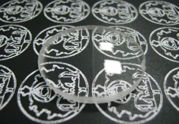
www.nature.com/scientificreports/
3 3
Vdip= 1 mm/s, Rave= 0.755 Vdip= 1 mm/s, Rave= 1.289
Vdip= 2 mm/s, Rave= 0.277 Vdip= 2 mm/s, Rave= 0.312
Reflectance (%)
Reflectance (%)
2 Vdip= 3 mm/s, Rave= 0.884 2 Vdip= 3 mm/s, Rave= 0.847
T = 67 °C T = 75 °C
1 1
0 0
400 500 600 700 800 400 500 600 700 800
Wavelength (nm) Wavelength (nm)
3
Vdip= 1 mm/s, Rave= 1.100
Vdip= 2 mm/s, Rave= 0.436
Reflectance (%)
2 Vdip= 3 mm/s, Rave= 0.861
T = 87 °C
1
0
400 500 600 700 800
Wavelength (nm)
Figure 2. Reflectance spectra measured from double side coated BK7 substrates with boomerang-like A
l2O3
films at different dipping-withdrawing rates (Vdip) and hot-water treatment temperatures (T).
studies have shown that high porosity occurs in the alumina layer at treatment temperatures above 60°C25,26,28.
Therefore, for temperatures above 60 degrees, the effect of treatment temperature on the optical performance of
alumina coating has been investigated. At all hot-water treatment temperatures of 67 °C, 75 °C and 87 °C, with
increasing dipping-withdrawing rate from 1 to 2 mm/s, initially the reflectance decreases, then with increasing
the rate up to 3 mm/s, the reflectance begin to increase. Among all these samples, the coatings prepared with a
dipping-withdrawing rate of 2 mm/s (creates a thickness of about 200 n m29) shows the lowest light reflectance
with average reflectance (Rave) of 0.277, 0.312 and 0.436% for hot-water treatment temperatures of 67 °C, 75 °C
and 87 °C, respectively. Since the thickness of the coated layer is directly related to the dipping-withdrawing rate,
increasing the rate causes the reflectance spectrum to have red-shifts as the layer thickness increases (as shown in
Fig. 2). The blue-shift of the reflectance spectrum with increasing hot-water treatment temperature from 67 °C to
75 °C and 87 °C can be due to more dissolution of alumina and reduction of layer thickness. Excessive increase
of this dissolution in the upper levels of alumina boomerang-like structure, which is more exposed to hot water,
can lead to increased light reflectance by increasing the slope of the refractive index profile. For example, in the
coating prepared with the rate of 2 mm/s, the light reflectance has increased over the entire visible spectral region
due to increasing the treatment temperature from 75 °C to 87 °C, while the layer thickness has not significantly
changed (inferred from this observation that there was no shift in the reflectance spectrum). Therefore, increasing
light reflectance can be attributed to increasing the slope of the refractive index profile during high dissolution
of the upper levels of the boomerang-like structure of alumina.
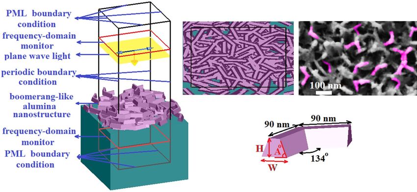
To further investigate the boomerang-like alumina nanostructure and extract its refractive index profile by fit-
ting the measured reflectance spectrum with the simulated one, a simulation based on the finite-difference time-
domain (FDTD) method has been performed (Fig. 3). The boomerang-like unit structure, inspired by the FESEM
image of the sample surface (Fig. 3a), has been used to design the alumina nanostructure. Nano-boomerangs
Scientific Reports | (2022) 12:904 | https://doi.org/10.1038/s41598-022-04928-2 3
Vol.:(0123456789)
www.nature.com/scientificreports/
(a)
3 1.4
Exp, Vdip= 1 mm/s, Rave= 0.755 % (b) Vdip= 1 mm/s
Effective Refractive Index (RIU)
1.3
Sim, Vdip= 1 mm/s, Rave= 0.633 % (c)
1.2
Exp, Vdip= 2 mm/s, Rave= 0.311 %
1.1
Reflectance (%)
2 Sim, Vdip= 2 mm/s, Rave= 0.290 % 1.4
Exp, Vdip= 3 mm/s, Rave= 0.847 % Vdip= 2 mm/s
1.3
Sim, Vdip= 3 mm/s, Rave= 0.777 % 1.2
1.1
1 1.4
Vdip= 3 mm/s
1.3
1.2
1.1
0 0 50 100 150 200 250 300
400 500 600 700 800
Wavelength (nm) Thickness (nm)
Figure 3. (a) Schematic diagram of the simulation model: perspective view (left) and top view (right). (b)
Spectral reflectance of double side coated samples with different dipping-withdrawing rates ( Vdip) from Fig. 2
(solid line) and simulated spectral reflectance (dash line). (c) The relationships between thickness position and
effective refractive index of boomerang-like A l2O3 films produced at different dipping-withdrawing rates (Vdip).
with a height, H of 50 nm, a width, W of 30 and 40 nm, and a basic angle, A of 77–83 degrees have been ran-
domly distributed (random position and rotation) on the surface of BK7 substrate so that thicknesses of 150,
200 and 300 nm with gradient refractive index profiles (Fig. 3c) have been created for the coatings fabricated at
dipping-withdrawing rates of 1, 2 and 3 mm/s, respectively. Figure 3b shows the measured reflectance spectra of
the fabricated anti-reflective coatings compared to the simulation results. The calculated reflectance spectrum is
in good agreement with the experimental spectra, which shows that the modeling performed in this work can
well describe the optical performance of the device. Figure 3c shows the variation of effective refractive index
with thickness for coated alumina nanostructures at rates of 1, 2 and 3 mm/s. Among them, the boomerang-like
alumina nanostructure coated at a rate of 2 mm/s and treated with deionized hot water for 30 min, which pro-
vides a gradient refractive index profile rated from 1.05 to 1.4 along the 200 nm thickness, has been presented
the best optical performance with the least amount of reflectance (Fig. 3b). The effective refractive index along
the alumina nanostructure has been calculated using Eq. (1) provided by Yoldas for porous nanostructures30.
p
n2p = n2 − 1 1 − (1)
+ 1,
100
where p, n, and np are the percent porosity, index of nonporous material, and index of porous material, respec-
tively. The percent porosity has been calculated using an index monitor along the nanostructure thickness and
image processing.
Figure 4a shows the reflectance and transmittance spectra of double-side boomerang-like alumina coated
BK7 substrates with the dipping-withdrawing rate of 2 mm/s and the hot-water treatment temperature of 67 °C
at the incidence angles of 0°, 12°, 30° and 45°. At the case of normal incidence, the average reflectance of BK7
has reduced from about 8% to 0.3% in the visible spectral region. Measurements at all incidence angles show
Scientific Reports | (2022) 12:904 | https://doi.org/10.1038/s41598-022-04928-2 4
Vol:.(1234567890)www.nature.com/scientificreports/
5.0 100 2.0 100
4.5
4.0 98 98
1.5
Transmittance (%)
Transmittance (%)
Reflectance (%)
3.5
Reflectance (%)
3.0 96 96
θ =0
(a) (b)
2.5 1.0
2.0 θ =12 94 94
1.5 θ =30
0.5
1.0 θ =45 92 Reflectance 92
Transmittance
0.5
0.0 90 0.0 90
400 450 500 550 600 650 700 400 500 600 700
Wavelength (nm) Wavelength (nm)
5.0 100
4.5 (c) (d)
4.0 98
Transmittance (%)
Reflectance (%)
3.5
3.0 96
2.5 Reflectance , Rave= 0.526 %
2.0 Transmittance , Tave= 97.96 % 94
1.5
1.0 92
0.5
0.0 90
400 600 800 1000 1200 1400
Wavelength (nm)
Figure 4. (a) Reflectance and transmittance spectra measured from double side coated BK7 substrates with
boomerang-like Al2O3 films at incident angles of 0°, 12°, 30° and 45°. (b) Reflectance and transmittance across a
boomerang-like alumina coated lens surface measured under light at normal incidence. The background image
in (b) shows that the transparency of the BK7 lens (the right part of lens) enhances remarkably in the presence
of boomerang-like alumina coating (the left part of lens). (c) Reflectance and transmittance across a boomerang-
like alumina coated lens surface measured under light at normal incidence. (d) Photograph of water droplet on
the superhydrophobic surfaces of boomerang-like alumina coated BK7 substrate.
a low average reflectance of less than 0.9%. Similarly, the average transmittance at the incidence angle of 45° is
above 96.5%, which is significantly higher than 92% for the blank BK7 at the normal incidence. Subsequently,
the optimized boomerang-like alumina coating is applied to a curved aspheric BK7 lens and its anti-reflective
performance is investigated (Fig. 4b). The measurements showed an average reflectance of less than 0.14% and
an average transmittance of above 99.3% in the visible spectral region (400–700 nm). To realize the effect of
broadband anti-reflection property in the visible wavelength range, optical images for a lens with and without
the proposed coating that was exposed to white light are shown in the background of Fig. 4b. The right part of
the lens (without the coating) looks a bit white and misty gray, and the image behind the lens cannot be clearly
seen due to the ghost image from the light. In general, the uncoated part reflects all kinds of visible light, and
the lens appears white. On the contrary, the left part of the lens (with the coating) shows increased transpar-
ency, and the real color of the background image is reproduced phenomenally even at oblique incidence angles.
It is noteworthy that this anti-reflective property of the proposed coating is not only restricted to the vis-
ible spectral region but also provide low reflectance (average of 0.526%) with very high transparency (average
transmittance of 97.96%) in the wavelength range of 400–1500 nm (Fig. 4c). Above all, this nanostructure shows
hydrophilic properties due to its roughness of less than 50 nm, which provides superhydrophobic properties
during the reduction of surface free energy using fluorosilane (Fig. 4d). In the case of BK7 glass substrate coated
with boomerang-like Al2O3 thin film, the contact angle for water drop is about 155°. Here, heptadecafluorodecyl-
trimethoxysilane, which is one of the fluoroalkyltrimethoxysilanes (FASs) was spin coated over boomerang-like
alumina coatings at 3000 RPM for 60 s and annealed at 180 °C for 30 min to obtain low energy surfaces.
The various techniques used to fabricate alumina-based single-layer anti-reflective coatings have been summa-
rized in Table 1. Lertvanithphol et al. have fabricated Al2O3 nanoflake films on a glass slide by reactive magnetron
sputtering and surface modification via hot water treatment and alkali treatment31. The developed anti-reflective
Scientific Reports | (2022) 12:904 | https://doi.org/10.1038/s41598-022-04928-2 5
Vol.:(0123456789)www.nature.com/scientificreports/
Substrate Fabrication method Al2O3 nanostructure Coated (uncoated) average R (%) Ref
31
Glass Reactive magnetron sputtering Nanoflake 4.12 (9.19)
32
Soda lime glass Spin-coating Nanoflakes 3.04 (7.29)
33
Solar cover glass Wire bar coating Nanoflakelet 1.59 (11.61)
26
PMMA Dip-coating Pseudo-boehmite nanocrystals 1.44 (8.06)
25
Soda lime glass Dip-coating Flowerlike 1.16 (9.76)
28
Soda lime glass Atomic layer deposition Grasslike 0.77 (8.09)
BK7 glass Dip-coating Boomeranglike 0.31 (7.85) T.W
Table 1. Comparison of various fabrication techniques used for Al2O3 based single-layer antireflection
coatings in visible region (400–700 nm).
coating reduced the average reflectance (both sides) from 9.19% to 4.12%. Using a solution-based approach and
spin coating technique, Sutha et al. have developed an amorphous alumina coating with an interconnected porous
network of nanoflakes on a soda glass s ubstrate32. The 300 nm thick coating produced an average reflectance of
3.04%. The hierarchical pseudo-boehmite nanoflakelets fabricated using custom-made wire bar coater on solar
cover glass by Joghee et al. reduced light reflectance to 1.59%33. In another study, pseudo-boehmite nanocrys-
tals formed on the surface of alumina gel by immersion in hot water, in which alumina was coated on the poly
(methyl methacrylate) PMMA substrate using sol–gel process and dip-coating technique, decreased the aver-
age reflectance from 8.06% to 1.44%26. Using a similar manufacturing process, Yamaguchi et al. have produced
flower-like alumina nanostructures on the soda glass substrate, which yielded an average reflectance of 1.16% in
the visible r egion25. Uniquely, Kauppinen et al. have fabricated a grass-like alumina-based anti-reflective coating
with a graded refractive index profile using atomic layer deposition (ALD) and the hot-water treatment process
on soda glass. By investigating and optimizing the water temperature in the treatment process, they reduced the
average reflectance from 8.09% to 0.77%28. Considering all of the above studies, we have used a cost-effective
and simple sol–gel process in which boomerang-like alumina nanostructures have been fabricated on the BK7
substrate in the environment atmosphere without humidity control. This anti-reflective coating, which can be
easily fabricated on aspheric lens using the proposed method, has achieved an average reflectance (both sides)
of less than 0.5% (~ 0.31%).
Conclusion
In conclusion, an omnidirectional and broadband antireflection coating based on the boomerang-like alumina
nanostructures prepared by dip-coating and hot-water treatment has been demonstrated. The effects of hot water
treatment temperature and the rate of dip-coating, which determines the thickness of the anti-reflective coating,
on its optical performance have been investigated. A low reflectance with an average reflectance of less than 0.3%
was realized in the visible spectral region at normal incidence (double-side) for the boomerang-like alumina
nanostructures fabricated with a rate of 2 mm/s (~ 200 nm) and a hot water treatment temperature of 67 °C. The
omnidirectional properties of the developed coating are discussed for incidence angles ranging from 0 to 45°.
The average reflectance for a double-side coated BK7 substrate has been less than 0.4% at 45° incidence angle.
An average transmittance of above 99.3% with optical losses of 0.56% is achieved for a double-side coated curved
aspheric BK7 lens. The proposed coating superiority is that the boomerang-like alumina nanostructure can be
applied on inclined surfaces in a broad wavelength range because of having a gradient refractive index profile. In
addition, the complete antireflection system can be coated in one process followed by one hot-water treatment.
Methods
Materials and preparation of Al2O3 sol. Aluminum-tri-sec-butoxide (Al(O-sec-Bu)3) was used as a
starting material. Al(O-sec-Bu)3 and isopropyl alcohol (i-PrOH) were mixed and stirred at room temperature
for 20 min. Ethylacetoacetate (EAcAc) was added to the solution as a chelating agent, and the solution was
stirred for 20 min. Then, diluted deionized water with i-PrOH was added dropwise to the solution for hydrolysis
process. The molar ratios of EAcAc, H 2O and i-PrOH to Al(O-sec-Bu)3 were kept to be 1, 1 and 20, r espectively27.
All materials were obtained from Merck Chemicals.
Film preparation and characterization. The coating was deposited on BK7 glasses via dip-coating man-
ner (with various drawing speed) in an ambient atmosphere without the humidity control. The obtained coat-
ing were heat-treated at 400 °C for 30 min to get porous Al2O3 films27,29. Then the porous A
l2O3 coatings were
immersed in hot water (with various temperature) for 60 min and, after being dried in an ambient atmosphere,
were heat-treated again at 400 °C for 30 min. UV–visible spectrophotometer (Shimadzu, UV-3100) was used to
measure the transmittance and reflectance of the coatings. The microstructural details of the coatings were inves-
tigated using high-resolution field emission scanning electron microscopy (FESEM, model Sigma VP, Zeiss).
Received: 15 November 2021; Accepted: 3 January 2022
Scientific Reports | (2022) 12:904 | https://doi.org/10.1038/s41598-022-04928-2 6
Vol:.(1234567890)www.nature.com/scientificreports/
References
1. Raut, H. K., Ganesh, V. A., Nair, A. S. & Ramakrishna, S. Anti-reflective coatings: A critical, in-depth review. Energy Environ. Sci.
4, 3779–3804 (2011).
2. Macleod, H. A. Thin Film Optical Filters, ed. Bristol, UK Inst. Phys. Pub (2001).
3. Li, X., Gao, J., Xue, L. & Han, Y. Porous polymer films with gradient-refractive-index structure for broadband and omnidirectional
antireflection coatings. Adv. Funct. Mater. 20, 259–265 (2010).
4. Buskens, P., Burghoorn, M., Mourad, M. C. D. & Vroon, Z. Antireflective coatings for glass and transparent polymers. Langmuir
32, 6781–6793 (2016).
5. Keshavarz Hedayati, M. & Elbahri, M. Antireflective coatings: Conventional stacking layers and ultrathin plasmonic metasurfaces,
a mini-review. Materials (Basel) 9, 497 (2016).
6. Chuang, S.-Y. et al. Nanoscale of biomimetic moth eye structures exhibiting inverse polarization phenomena at the Brewster angle.
Nanoscale 2, 799–805 (2010).
7. Pfeiffer, K., Ghazaryan, L., Schulz, U. & Szeghalmi, A. Wide-angle broadband antireflection coatings prepared by atomic layer
deposition. ACS Appl. Mater. Interfaces 11, 21887–21894 (2019).
8. Sassolas, B. et al. Masking technique for coating thickness control on large and strongly curved aspherical optics. Appl. Opt. 48,
3760–3765 (2009).
9. Gross, M., Dligatch, S. & Chtanov, A. Optimization of coating uniformity in an ion beam sputtering system using a modified
planetary rotation method. Appl. Opt. 50, C316–C320 (2011).
10. Glocker, D., Lanzafame, J., Belan, R., Griffin, N. & Armstrong, S. System for sputtering uniform optical coatings on flat and curved
surfaces without masks (2016).
11. Kaddouri, A. M., Kouzou, A., Hafaifa, A. & Khadir, A. Optimization of anti-reflective coatings using a graded index based on
silicon oxynitride. J. Comput. Electron. 18, 971–981 (2019).
12. Wilson, C. R. et al. Anti-reflective structured surfaces on soda-lime windows for high power laser applications. in Advanced Optics
for Imaging Applications: UV through LWIR V vol. 11403 114030H (2020).
13. Liu, F. et al. High performance ZnS antireflection sub-wavelength structures with HfO 2 protective film for infrared optical win-
dows. Opt. Express 29, 31058–31067 (2021).
14. Pickering, T., Shanks, K. & Sundaram, S. Modelling technique and analysis of porous anti-reflective coatings for reducing wide
angle reflectance of thin-film solar cells. J. Opt. 23, 25901 (2021).
15. Behera, S., Fry, P. W., Francis, H., Jin, C.-Y. & Hopkinson, M. Broadband, wide-angle antireflection in GaAs through surface nano-
structuring for solar cell applications. Sci. Rep. 10, 1–10 (2020).
16. Bernhard, C. G. Structural and functional adaptation in a visual system. Endeavour 26, 79–84 (1967).
17. Kikuta, H., Toyota, H. & Yu, W. Optical elements with subwavelength structured surfaces. Opt. Rev. 10, 63–73 (2003).
18. Wilson, S. J. & Hutley, M. C. The optical properties of ’moth eye’antireflection surfaces. Opt. Acta Int. J. Opt. 29, 993–1009 (1982).
19. Huh, D., Choi, H.-J., Byun, M., Kim, K. & Lee, H. Long-term analysis of PV module with large-area patterned anti-reflective film.
Renew. Energy 135, 525–528 (2019).
20. Xu, H. et al. Biomimetic moth-eye anti-reflective poly-(methyl methacrylate) nanostructural coating. J. Bionic Eng. 16, 1030–1038
(2019).
21. Lim, S. H. et al. Nanopatterned polymer molds using anodized aluminum templates for anti-reflective coatings. Polymers (Basel)
13, 3333 (2021).
22. Oh, K.-S., Cho, S.-H., Choi, J.-Y., Lee, K. & Chan, S. Improved reliability PERC PV modules with moth-eye nanostructured optical
films using nano imprint lithography. Microelectron. Reliab. 114320 (2021).
23. Choi, J. S., An, J. H., Lee, J.-K., Ku, S. J. & Kang, S. M. Analysis of optical and wetting properties of a biomimetic anti-reflective
surface for practical application. J. Mech. Sci. Technol. 35, 3559–3567 (2021).
24. Zhang, S., Xiao, P., Wang, P., Luo, J. & Jiang, B. Spherical-chain silica with super-hydrophobic surface and ultra-low refractive
index for multi-functional broadband antireflective coatings. Sol. Energy 207, 1222–1230 (2020).
25. Yamaguchi, N., Tadanaga, K., Matsuda, A., Minami, T. & Tatsumisago, M. Antireflective properties of flowerlike alumina thin films
on soda–lime silica glass substrates prepared by the sol–gel method with hot water treatment. Thin Solid Films 515, 3914–3917
(2007).
26. Tadanaga, K. et al. Anti-reflective properties of nano-structured alumina thin films on poly (methyl methacrylate) substrates by
the sol–gel process with hot water treatment. Thin Solid Films 516, 4526–4529 (2008).
27. Yamaguchi, N., Tadanaga, K., Matsuda, A., Minami, T. & Tatsumisago, M. Anti-reflective coatings of flowerlike alumina on various
glass substrates by the sol–gel process with the hot water treatment. J. Sol-gel Sci. Technol. 33, 117–120 (2005).
28. Kauppinen, C., Isakov, K. & Sopanen, M. Grass-like alumina with low refractive index for scalable, broadband, omnidirectional
antireflection coatings on glass using atomic layer deposition. ACS Appl. Mater. Interfaces 9, 15038–15043 (2017).
29. Tadanaga, K., Katata, N. & Minami, T. Super-water-repellent Al2O3 coating films with high transparency. J. Am. Ceram. Soc. 80,
1040–1042 (1997).
30. Yoldas, B. E. Investigations of porous oxides as an antireflective coating for glass surfaces. Appl. Opt. 19, 1425–1429 (1980).
31. Lertvanithphol, T. et al. Facile fabrication and optical characterization of nanoflake aluminum oxide film with high broadband
and omnidirectional transmittance enhancement. Opt. Mater. 111, 110567 (2021).
32. Sutha, S., Suresh, S., Raj, B. & Ravi, K. R. Transparent alumina based superhydrophobic self–cleaning coatings for solar cell cover
glass applications. Sol. Energy Mater. Sol. Cells 165, 128–137 (2017).
33. Joghee, S. H. et al. Superhydrophobic coatings based on pseudoboehmite nanoflakelets for sustainable photovoltaic energy produc-
tion. ACS Appl. Nano Mater. 3, 9899–9911 (2020).
Author contributions
M. K. Omrani: Conceptualization, Validation, Formal analysis, Investigation, Writing—original draft, Writing-
review & editing, Resources, Visualization, Supervision, Project administration. M. Malekmohammad: Supervi-
sion, Writing—review & editing. H. Zabolian: Writing—review & editing.
Competing interests
The authors declare no competing interests.
Additional information
Correspondence and requests for materials should be addressed to M.O. or M.M.
Reprints and permissions information is available at www.nature.com/reprints.
Publisher’s note Springer Nature remains neutral with regard to jurisdictional claims in published maps and
institutional affiliations.
Scientific Reports | (2022) 12:904 | https://doi.org/10.1038/s41598-022-04928-2 7
Vol.:(0123456789)www.nature.com/scientificreports/
Open Access This article is licensed under a Creative Commons Attribution 4.0 International
License, which permits use, sharing, adaptation, distribution and reproduction in any medium or
format, as long as you give appropriate credit to the original author(s) and the source, provide a link to the
Creative Commons licence, and indicate if changes were made. The images or other third party material in this
article are included in the article’s Creative Commons licence, unless indicated otherwise in a credit line to the
material. If material is not included in the article’s Creative Commons licence and your intended use is not
permitted by statutory regulation or exceeds the permitted use, you will need to obtain permission directly from
the copyright holder. To view a copy of this licence, visit http://creativecommons.org/licenses/by/4.0/.
© The Author(s) 2022
Scientific Reports | (2022) 12:904 | https://doi.org/10.1038/s41598-022-04928-2 8
Vol:.(1234567890)You can also read


