UM2242 USER MANUAL GETTING STARTED WITH MICROSOFT AZURE IOT CLOUD EXPANSION PACKAGE FOR STM32CUBE
←
→
Page content transcription
If your browser does not render page correctly, please read the page content below
UM2242
                                                                                User manual
                               Getting started with Microsoft® Azure® IoT cloud
                                           Expansion Package for STM32Cube

               Introduction
               This user manual describes the content of the STM32 Microsoft® Azure® IoT (Internet of
               things) cloud STM32Cube Expansion Package.
               Microsoft Azure is a cloud computing service created by Microsoft for building, testing,
               deploying, and managing applications and services through a global network of Microsoft
               managed data centers. It provides software as a service (SaaS), platform as a service
               (PaaS), and infrastructure as a service (IaaS) and supports many different programming
               languages, tools, and frameworks, including both Microsoft-specific and third-party software
               and systems.
               The Microsoft Azure IoT Expansion Package (X-CUBE-AZURE) provides application
               examples that connect STMicroelectronics boards to the Azure IoT Hub.
               X-CUBE-AZURE runs on the B-L475E-IOT01A, 32F413HDISCOVERY and
               32F769IDISCOVERY Discovery kits, and P-L496G-CELL02 Discovery pack.
               Implementation examples are included for device-to-cloud telemetry reporting and cloud-to-
               device messages for sending commands and notifications to the connected devices.
               The X-CUBE-AZURE features are as follows:
               • Ready to run firmware example using Wi-Fi®, cellular and Ethernet connectivity to support
                 quick evaluation and development of Azure device applications
               • Console-based user interface to configure the board for connection to the Azure IoT Hub
               • Connection to the Azure IoT Hub and various call-back registrations
               • Azure IoT Hub, and bidirectional communication examples implemented
               • B-L475E-IOT01A measures and reports the following values:
                 – Humidity
                 – Temperature
                 – 3-axis magnetic data
                 – 3-axis acceleration
                 – 3-axis gyroscope data
                 – Atmospheric pressure
                 – Proximity

January 2022                                   UM2242 Rev 3                                             1/48
                                                                                                   www.st.com   1
Contents                                                                                                                       UM2242

Contents

1          General information . . . . . . . . . . . . . . . . . . . . . . . . . . . . . . . . . . . . . . . . . 6
           1.1      Acronyms . . . . . . . . . . . . . . . . . . . . . . . . . . . . . . . . . . . . . . . . . . . . . . . . . . 6
           1.2      References . . . . . . . . . . . . . . . . . . . . . . . . . . . . . . . . . . . . . . . . . . . . . . . . . 7

2          Azure IoT Hub . . . . . . . . . . . . . . . . . . . . . . . . . . . . . . . . . . . . . . . . . . . . . . 8

3          Package description . . . . . . . . . . . . . . . . . . . . . . . . . . . . . . . . . . . . . . . . . 9
           3.1      General description . . . . . . . . . . . . . . . . . . . . . . . . . . . . . . . . . . . . . . . . . . 9
           3.2      Architecture . . . . . . . . . . . . . . . . . . . . . . . . . . . . . . . . . . . . . . . . . . . . . . . 10
           3.3      Folder structure . . . . . . . . . . . . . . . . . . . . . . . . . . . . . . . . . . . . . . . . . . . . 12
           3.4      B-L475E-IOT01A board sensors . . . . . . . . . . . . . . . . . . . . . . . . . . . . . . . 16
           3.5      Wi-Fi® components . . . . . . . . . . . . . . . . . . . . . . . . . . . . . . . . . . . . . . . . . 17
           3.6      Reset push-button . . . . . . . . . . . . . . . . . . . . . . . . . . . . . . . . . . . . . . . . . . 17
           3.7      User push-button . . . . . . . . . . . . . . . . . . . . . . . . . . . . . . . . . . . . . . . . . . . 17
           3.8      User LED . . . . . . . . . . . . . . . . . . . . . . . . . . . . . . . . . . . . . . . . . . . . . . . . . 17
           3.9      Real-time clock . . . . . . . . . . . . . . . . . . . . . . . . . . . . . . . . . . . . . . . . . . . . . 17
           3.10     mbedTLS configuration . . . . . . . . . . . . . . . . . . . . . . . . . . . . . . . . . . . . . . 18
           3.11     Secure Boot loader . . . . . . . . . . . . . . . . . . . . . . . . . . . . . . . . . . . . . . . . . . 18
                    3.11.1      Overview . . . . . . . . . . . . . . . . . . . . . . . . . . . . . . . . . . . . . . . . . . . . . . . . 18
                    3.11.2      Application boot . . . . . . . . . . . . . . . . . . . . . . . . . . . . . . . . . . . . . . . . . . . 20
                    3.11.3      Building the whole firmware image . . . . . . . . . . . . . . . . . . . . . . . . . . . . 21
                    3.11.4      Rebuilding the bootloader . . . . . . . . . . . . . . . . . . . . . . . . . . . . . . . . . . . 23
                    3.11.5      Firmware update . . . . . . . . . . . . . . . . . . . . . . . . . . . . . . . . . . . . . . . . . . 25

4          Hardware and software environment setup . . . . . . . . . . . . . . . . . . . . . 28

5          Interacting with the boards . . . . . . . . . . . . . . . . . . . . . . . . . . . . . . . . . . 30

6          Application examples . . . . . . . . . . . . . . . . . . . . . . . . . . . . . . . . . . . . . . . 32
           6.1      Application description . . . . . . . . . . . . . . . . . . . . . . . . . . . . . . . . . . . . . . . 32
           6.2      Application setup . . . . . . . . . . . . . . . . . . . . . . . . . . . . . . . . . . . . . . . . . . . 32
                    6.2.1       Azure account creation . . . . . . . . . . . . . . . . . . . . . . . . . . . . . . . . . . . . . 32
                    6.2.2       CLI setup . . . . . . . . . . . . . . . . . . . . . . . . . . . . . . . . . . . . . . . . . . . . . . . . 32

2/48                                                 UM2242 Rev 3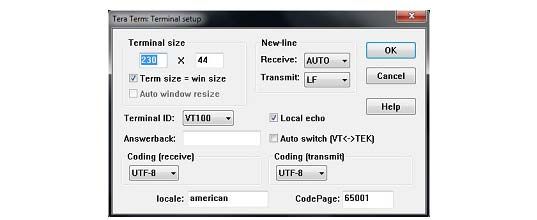
UM2242                                                                                                                 Contents

                  6.2.3       Azure IoT Hub creation . . . . . . . . . . . . . . . . . . . . . . . . . . . . . . . . . . . . . 33
                  6.2.4       Azure device creation . . . . . . . . . . . . . . . . . . . . . . . . . . . . . . . . . . . . . . 33
                  6.2.5       Application build and programming . . . . . . . . . . . . . . . . . . . . . . . . . . . . 34
                  6.2.6       Firmware programming on the STM32 board . . . . . . . . . . . . . . . . . . . . 34
                  6.2.7       Application first launch . . . . . . . . . . . . . . . . . . . . . . . . . . . . . . . . . . . . . . 34
         6.3      Application runtime . . . . . . . . . . . . . . . . . . . . . . . . . . . . . . . . . . . . . . . . . . 35
         6.4      Authentication methods . . . . . . . . . . . . . . . . . . . . . . . . . . . . . . . . . . . . . . 39
                  6.4.1       Symmetric keys . . . . . . . . . . . . . . . . . . . . . . . . . . . . . . . . . . . . . . . . . . . 39
                  6.4.2       X.509 self-signed certificate . . . . . . . . . . . . . . . . . . . . . . . . . . . . . . . . . . 40
                  6.4.3       X.509 CA certificate . . . . . . . . . . . . . . . . . . . . . . . . . . . . . . . . . . . . . . . . 40
                  6.4.4       Device Provisioning Service . . . . . . . . . . . . . . . . . . . . . . . . . . . . . . . . . 42

7        Memory organization . . . . . . . . . . . . . . . . . . . . . . . . . . . . . . . . . . . . . . . 44

8        Frequently asked questions . . . . . . . . . . . . . . . . . . . . . . . . . . . . . . . . . . 46

9        Revision history . . . . . . . . . . . . . . . . . . . . . . . . . . . . . . . . . . . . . . . . . . . 47

                                                  UM2242 Rev 3                                                                 3/48
                                                                                                                                        3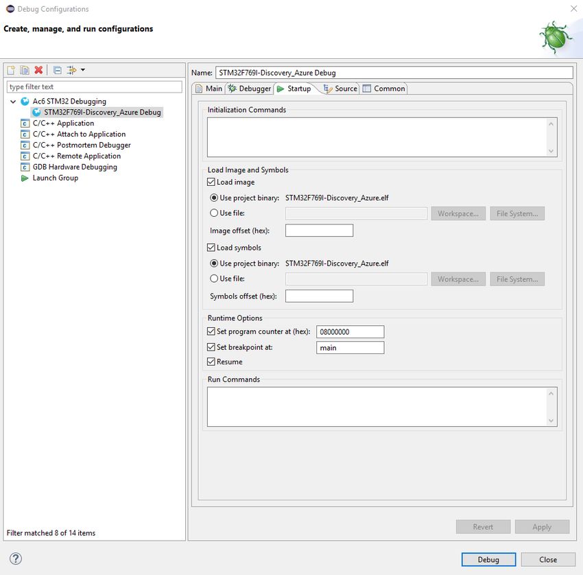
List of tables                                                                                                                       UM2242

List of tables

Table 1.    List of acronyms . . . . . . . . . . . . . . . . . . . . . . . . . . . . . . . . . . . . . . . . . . . . . . . . . . . . . . . . . . 6
Table 2.    Reference documents. . . . . . . . . . . . . . . . . . . . . . . . . . . . . . . . . . . . . . . . . . . . . . . . . . . . . . 7
Table 3.    Units for the values reported by the sensors of the B-L475E-IOT01A board . . . . . . . . . . . 16
Table 4.    Azure CLI command lines. . . . . . . . . . . . . . . . . . . . . . . . . . . . . . . . . . . . . . . . . . . . . . . . . . 37
Table 5.    Memory footprint values . . . . . . . . . . . . . . . . . . . . . . . . . . . . . . . . . . . . . . . . . . . . . . . . . . . 44
Table 6.    Document revision history . . . . . . . . . . . . . . . . . . . . . . . . . . . . . . . . . . . . . . . . . . . . . . . . . 47

4/48                                                       UM2242 Rev 3
UM2242                                                                                                                          List of figures

List of figures

Figure 1.    Azure IoT ecosystem . . . . . . . . . . . . . . . . . . . . . . . . . . . . . . . . . . . . . . . . . . . . . . . . . . . . . . 8
Figure 2.    X-CUBE-AZURE software architecture. . . . . . . . . . . . . . . . . . . . . . . . . . . . . . . . . . . . . . . . 11
Figure 3.    Top folders . . . . . . . . . . . . . . . . . . . . . . . . . . . . . . . . . . . . . . . . . . . . . . . . . . . . . . . . . . . . . 12
Figure 4.    Drivers . . . . . . . . . . . . . . . . . . . . . . . . . . . . . . . . . . . . . . . . . . . . . . . . . . . . . . . . . . . . . . . . 13
Figure 5.    Middleware . . . . . . . . . . . . . . . . . . . . . . . . . . . . . . . . . . . . . . . . . . . . . . . . . . . . . . . . . . . . . 14
Figure 6.    Projects and utilities . . . . . . . . . . . . . . . . . . . . . . . . . . . . . . . . . . . . . . . . . . . . . . . . . . . . . . 15
Figure 7.    Application boot - console feedback . . . . . . . . . . . . . . . . . . . . . . . . . . . . . . . . . . . . . . . . . . 20
Figure 8.    Image build flow . . . . . . . . . . . . . . . . . . . . . . . . . . . . . . . . . . . . . . . . . . . . . . . . . . . . . . . . . 21
Figure 9.    Post-processing log file example . . . . . . . . . . . . . . . . . . . . . . . . . . . . . . . . . . . . . . . . . . . . 22
Figure 10.   Program counter setting with the SW4STM32 IDE. . . . . . . . . . . . . . . . . . . . . . . . . . . . . . . 25
Figure 11.   Hardware and software setup environment . . . . . . . . . . . . . . . . . . . . . . . . . . . . . . . . . . . . 28
Figure 12.   Terminal setup . . . . . . . . . . . . . . . . . . . . . . . . . . . . . . . . . . . . . . . . . . . . . . . . . . . . . . . . . . 30
Figure 13.   Serial port setup . . . . . . . . . . . . . . . . . . . . . . . . . . . . . . . . . . . . . . . . . . . . . . . . . . . . . . . . . 31
Figure 14.   Runtime state flow . . . . . . . . . . . . . . . . . . . . . . . . . . . . . . . . . . . . . . . . . . . . . . . . . . . . . . . 36
Figure 15.   STM32F413 Keil® Azure linker file example. . . . . . . . . . . . . . . . . . . . . . . . . . . . . . . . . . . . 45
Figure 16.   Pop-up when the IAR Embedded Workbench® IDE version
             is not compatible with the one used for X-CUBE-AZURE. . . . . . . . . . . . . . . . . . . . . . . . . . 46

                                                              UM2242 Rev 3                                                                      5/48
                                                                                                                                                          5
General information UM2242
1 General information
The X-CUBE-AZURE Expansion Package runs on STM32 32-bit microcontrollers based on
the Arm®(a) Cortex®-M processor.
1.1 Acronyms
Table 1 presents the definition of acronyms that are relevant for a better understanding of
this document.
Table 1. List of acronyms
Term Definition
API Application programming interface
BSP Board support package
C2D Cloud to device
CA Certification authority
CLI Command-line interface
CSR Certificate signing request
D2C Device to cloud
DHCP Dynamic host configuration protocol
DNS Domain name server
DPS Device Provisioning Service
HAL Hardware abstraction layer
HSM Hardware security module
IDE Integrated development environment
IoT Internet of things
IP Internet protocol
JSON JavaScript object notation
LED Light-emitting diode
RTC Real-time clock
SBSFU Secure Boot and Secure Firmware Update
TLS Transport layer security
UART Universal asynchronous receiver/transmitter
a. Arm is a registered trademark of Arm Limited (or its subsidiaries) in the US and/or elsewhere.
All other trademarks are the property of their respective owners.
6/48 UM2242 Rev 3UM2242 General information
1.2 References
Table 2 presents STMicroelectronics documents providing complementary information
about the topics presented in this user manual. These documents are available from
STMicroelectronics web site at www.st.com.
Table 2. Reference documents
Identifier Title
Getting started with the X-CUBE-CELLULAR cellular connectivity
UM2567
Expansion Package for STM32Cube user manual.
X-CUBE-CELLULAR cellular connectivity Expansion Package for
UM2426
STM32Cube user manual.
Getting started with the X-CUBE-SBSFU STM32Cube Expansion Package user
UM2262
manual.
Integration guide for the X-CUBE-SBSFU STM32Cube Expansion Package
AN5056
application note.
UM2242 Rev 3 7/48
47Azure IoT Hub UM2242
2 Azure IoT Hub
This section introduces the Azure IoT Hub service.
The X-CUBE-AZURE Expansion Package implements Azure IoT device SDK in C
language, which allows the board to securely connect to the Azure IoT Hub service.
A user can connect to the cloud with a smartphone or personal computer and have access
to the information provided by the board at any time and from any location.
Figure 1 presents the Azure IoT ecosystem targeted by the X-CUBE-AZURE Expansion
Package. X-CUBE-AZURE implements the connection of the device to the Azure IoT Hub
service with the MQTT protocol. The Apps / Browser and other transport protocols are only
shown in Figure 1 for information as existing Azure features.
Figure 1. Azure IoT ecosystem
In addition to a rich set of device-to-cloud (D2C) and cloud-to-device (C2D) communication
options, including messaging and request-reply methods, Azure IoT Hub addresses device-
connectivity in the following ways:
• Device twins. Using device twins, users can store, synchronize, and query device
metadata and state information. Device twins are JSON documents that store device
state information (metadata, configurations, and conditions). IoT Hub persists a device
twin for each device connected to IoT Hub.
• Per-device authentication and secure connectivity. Users can provision each device
with security credentials to enable it to connect to IoT Hub. The IoT Hub identity
registry stores device identities and keys in a solution. A solution back end can add
individual devices to allow or deny lists to enable complete control over device access.
The Device Provisioning Service is a helper service for IoT Hub that enables zero-touch,
just-in-time provisioning to the right IoT hub without requiring human intervention, enabling
customers to provision millions of devices in a secure and scalable manner.
For a complete description of Microsoft® Azure® and Azure IoT Hub, refer to the information
available at the overview of the Azure IoT Hub service webpage.
8/48 UM2242 Rev 3UM2242 Package description
3 Package description
This section details the X-CUBE-AZURE Expansion Package content and the way to use it.
3.1 General description
The X-CUBE-AZURE Expansion Package provides an Azure stack middleware for STM32
microcontrollers.
It is ported to the B-L475E-IOT01A, 32F413HDISCOVERY and 32F769IDISCOVERY
Discovery kits and to the P-L496G-CELL02 Discovery pack. It connects to the Internet
through their on-board or attached network interface:
• B-L475E-IOT01A supports Wi-Fi connectivity with an on-board Inventek module. This
board is equipped with a set of sensors able to report humidity, temperature, 3-axis
magnetic data, 3-axis accelerations, 3-axis gyroscope data, atmospheric pressure,
proximity and gesture detection (X-CUBE-AZURE does not use the gesture detection
capability).
• 32F413HDISCOVERY supports Wi-Fi connectivity with an on-board Inventek module.
• 32F769IDISCOVERY provides a native Ethernet interface.
• P-L496G-CELL02 supports cellular connectivity with a Quectel BG96 modem (LTE Cat
M1/NB/2G fallback) expansion board associated to an STM32L496AGI6-based low-
power Discovery board (screenless 32L496GDISCOVERY).
The package is split into the following components:
• C99 SDK for connecting devices to Microsoft® Azure® IoT services
• mbedTLS
• LwIP
• FreeRTOS™
• Wi-Fi drivers
• Ethernet driver for the 32F769IDISCOVERY board
• Sensor drivers for the B-L475E-IOT01A board
• STM32L4 Series, STM32F4 Series, and STM32F7 Series HAL
• Secure Boot loader derived from the X-CUBE-SBSFU Expansion Package
• Cellular library derived from the X-CUBE-CELLULAR Expansion Package
• Network library
• Azure application examples
The software is provided as a zip archive containing source code.
The following integrated development environments are supported:
• IAR Embedded Workbench® for Arm® (EWARM)
• Keil® Microcontroller Development Kit (MDK-ARM)
• System Workbench for STM32 (SW4STM32)
UM2242 Rev 3 9/48
47Package description UM2242
3.2 Architecture
This section describes the software components of the X-CUBE-AZURE Expansion
Package.
X-CUBE-AZURE is an Expansion Package for STM32Cube. Its main features and
characteristics are:
• Fully compliant with STM32Cube architecture
• Expands STM32Cube in order to enable the development of applications accessing
and using the Azure IoT
• Based on the STM32Cube HAL, which is the hardware abstraction layer for STM32
microcontrollers
The software components used by the application software to access and use the Azure IoT
Hub are the following:
• STM32Cube HAL
The HAL driver layer provides a generic multi-instance simple set of APIs (application
programming interfaces) to interact with the upper layers (application, libraries and
stacks).
It is composed of generic and extension APIs. It is directly built around a generic
architecture and allows the layers that are built upon, such as the middleware layer, to
implement their functionalities without dependencies on the specific hardware
configuration for a given microcontroller unit (MCU).
This structure improves the library code reusability and guarantees an easy portability
onto other devices.
• Board support package (BSP)
The software package needs to support the peripherals on the STM32 boards apart
from the MCU. This software is included in the board support package (BSP). This is a
limited set of APIs that provides a programming interface for certain board specific
peripherals such as the LED and the user button.
• Azure middleware
It is composed of the Azure IoT Hub client library, Device Provisioning Service client
library, a JSON parser, a JSON serializer, an MQTT client (used as a transport layer by
the IoT Hub client library), and various C utilities used by the client library.
• mbedTLS
The Azure middleware uses a TLS connection that is managed by the mbedTLS
library.
• TCP/IP
The TCP/IP connection can be handled either by the Wi-Fi module, cellular module, or
LwIP middleware (when an Ethernet connection is being used). In the X-CUBE-AZURE
Expansion Package, only the 32F769IDISCOVERY board can connect via the
Ethernet.
• FreeRTOS™
It is a real-time operating system required by LwIP and X-CUBE-CELLULAR.
10/48 UM2242 Rev 3UM2242 Package description
• Secure Boot and Secure Firmware Update
– Secure Boot loader: manages application verification and authentication at boot
time.
– Secure Firmware Upgrade: manages firmware update in a trusted secure way.
The Secure Boot and Secure Firmware Update solution is derived from the X-CUBE-
SBSFU Expansion Package. Some elementary components of the X-CUBE-SBSFU
Expansion Package are pre-integrated in the X-CUBE-AZURE Expansion Package.
• Cellular framework
The Cellular framework is the software stack allowing the drive of cellular modems from
an STM32 MCU.
• STM32 Network library
The STM32 Network library provides an API to access network services on STM32
devices. It supports several network adapters and several protocols. This API is
intended for any STM32Cube application requiring network services.
Figure 2 outlines X-CUBE-AZURE software architecture.
Figure 2. X-CUBE-AZURE software architecture
Sample applications User PC
application software
Application level demonstrations
Azure® Network LwIP Cellular SBSFU mbedTLS FreeRTOS™
Utilities
Middleware level
Board support package (BSP) Hardware abstraction layer (HAL)
CMSIS
Drivers
STM32 Wi-Fi® module Ethernet Cellular modem Sensors
Hardware components
32F413HDISCOVERY 32F769IDISCOVERY P-L496G-CELL02 B-L475E-IOT01A
Development boards
MSv46849V4
UM2242 Rev 3 11/48
47Package description UM2242
3.3 Folder structure
Figure 3 presents the top folder structure of the X-CUBE-AZURE package. Figure 4:
Drivers, Figure 5: Middleware, and Figure 6: Projects and utilities further detail the top folder
contents.
Figure 3. Top folders
X.Y.Z is an abstraction for the version used
HALs and BSPs
Generic software not tied to specific STM32
Board-specific application examples
MSv63395V1
12/48 UM2242 Rev 3UM2242 Package description
Figure 4. Drivers
BSPv1 sources for the B-L475E-IOT01A board
Sources for on-board components
Common APIs for on-board components (sensors)
Sources for external modems
(used in P-L496G-CELL02 with the screenless
32L496GDISCOVERY board)
BSPv2 sources for the B-L475E-IOT01A board
HALs for STM32L4xx devices
MSv63396V1
UM2242 Rev 3 13/48
47Package description UM2242
Figure 5. Middleware
Middleware for Cellular connectivity
(screenless 32L496GDISCOVERY in P-L496G-CELL02)
Middleware for Network library
Middleware for Secure Boot
Microsoft® Azure® IoT C SDK
Contains the usertrust_baltimore.pem file, a
concatenation of 2 certificates to authenticate the
remote hosts through TLS
Azure® IoT C SDK example on STM32
FreeRTOS™ middleware
LwIP TCP/IP stack
mbedTLS network security middleware
MSv63397V1
14/48 UM2242 Rev 3UM2242 Package description
Figure 6. Projects and utilities
Sources of bootloader (Open Source Cryptography) for
the 32L496GDISCOVERY board (P-L496G-CELL02)
Azure® IoT application for the 32L496GDISCOVERY
board (P-L496G-CELL02)
Miscellaneous common sources
Cloud utility libraries
MSv63398V1
UM2242 Rev 3 15/48
47Package description UM2242
3.4 B-L475E-IOT01A board sensors
The sensors that are present on the board and used by the sample application are:
• Capacitive digital sensor for relative humidity and temperature (HTS221)
• High-performance 3-axis magnetometer (LIS3MDL)
• 3-axis accelerometer and 3-axis gyroscope (LSM6DSL)
• 260-1260 hPa absolute digital output barometer (LPS22HB)
• Proximity sensor (VL53L0X)
Example of a published sensor message:
{
"mac": "",
"temperature": 31.39856,
"humidity": 29.069721,
"pressure": 997.830017,
"proximity": 8190,
"accX": -13,
"accY": -14,
"accZ": 1024,
"gyrX": 1750,
"gyrY": -4970,
"gyrZ": 1470,
"magX": 170,
"magY": -180,
"magZ": 605,
"ts": "2017-06-07T15:14:22Z"
}
Table 3 presents the units for the values reported by the sensors of the B-L475E-IOT01A
board.
Table 3. Units for the values reported by the sensors of the B-L475E-IOT01A board
Data Unit
Temperature degree Celsius (°C)
Humidity relative humidity (%)
Pressure hectopascal (hPa)
Proximity millimeter (mm)
Acceleration milli g-force (mgforce)
Angular velocity millidegree per second (mdps)
Magnetic induction milligauss (mG)
16/48 UM2242 Rev 3UM2242 Package description
3.5 Wi-Fi® components
The Wi-Fi software is split over Drivers/BSPv2/Components for module-specific software
and Projects//Application/Cloud/Azure/Src/net_conf.c for I/O operations and Wi-Fi
module abstraction.
3.6 Reset push-button
The reset push-button (black) is used to reset the board at any time. This action makes the
board reboot.
3.7 User push-button
The user push-button (blue) is used in the following cases:
• To configure the Wi-Fi, cellular and Azure security credentials. This can be done from
the time that the board starts up and up to five seconds after that.
• When the board has been initialized to control the way data are published to the Azure
IoT Hub refer to Figure 14
The application configures and manages the user button via the board support package
(BSP) functions.
The BSP functions are in the Drivers\BSPv2 (or BSP)\ directory.
When using the BSP button functions with the BUTTON_USER value, the application does
not take into account the way this button is connected from a hardware standpoint for a
given platform. The mapping is handled by the BSP.
3.8 User LED
The user LED configuration is done via the board support package (BSP) functions.
The BSP functions are under the Drivers\BSP\ directory.
Using the BSP button functions with the LED_GREEN value, the application does not need to
take into account the way the LED is mapped for a given platform. The mapping is handled
by the BSP.
3.9 Real-time clock
The STM32 RTC is updated at startup from the www.gandi.net web server.
The user can use the HAL_RTC_GetTime() or time() function to get the time value.
These functions can for instance be used to time stamp messages.
UM2242 Rev 3 17/48
47Package description UM2242
3.10 mbedTLS configuration
The mbedTLS middleware support is fully configurable by means of a #include
configuration file.
The name of the configuration file can be overridden by means of the
MBEDTLS_CONFIG_FILE #define.
The X-CUBE-AZURE package uses file mbedtls_config.h for project configuration.
This is implemented by having the following # directives at the beginning of the mbedTLS.c
and mbedTLS.h files:
#if !defined(MBEDTLS_CONFIG_FILE)
#include "mbedtls/config.h"
#else
#include MBEDTLS_CONFIG_FILE
#endif
The configuration file specifies the ciphers to integrate.
3.11 Secure Boot loader
3.11.1 Overview
The pre-integrated bootloader allows the update of the user application (initially, the Azure
IoT sample application), adding new features, and correcting potential issues. This is
performed in a secure way, which prevents any unauthorized update or any access to
confidential embedded data such as secret code and firmware encryption key.
The secure bootloader enforces hardware security mechanisms on STM32. It guarantees a
unique entry point after reset, ensures immutable boot code, enforces security check and
performs firmware image verification (authenticity and integrity) before execution.
It takes advantage of hardware protection mechanisms present in STM32 devices:
• RDP-L2: read data protection (disables external access, protects boot options)
• WRP/PCROP: write data protection (protects code and keys from Flash memory dump,
protects trusted code)
• MPU: execution allowed in a chain of trust
• Firewall: protects Flash memory and RAM at runtime (secure enclave for critical
operations)
The secure bootloader is a standalone executable. It is delivered in the package both as a
pre-built executable file, and as source files, allowing advanced users to rebuild it with
different settings.
The delivered pre-compiled bootloader does not enforce security, so that the user can still
plug a debugger and debug the application.
Pre-compiled bootloader settings:
• Dual-image mode
• Enable local loader
• Secure IP turned off
• AES-GCM symmetric cryptography
18/48 UM2242 Rev 3UM2242 Package description
The dual-image mode enables safe image update, with firmware image backup and rollback
capabilities. The Flash memory is split in two areas named Slot #0 and Slot #1. The Slot #0
area contains the active firmware (firmware header + firmware). The Slot#1 area can be
written a downloaded firmware (firmware header + encrypted firmware) to be decrypted and
installed at next reboot. A specific Flash memory area is used to swap the content of Slot #0
and Slot #1 during the installation process at boot time. Using those two slots, firmware
update supports a rollback mechanism if an error happens at first execution of a new
installed firmware.
The bootloader integration is done in a seamless way, so that the user can keep using the
IDE as used to, when programming the board or debugging.
By contrast to the usual build flow (compile/link/program/debug), specific pre- and post-build
phases have been added to the sample projects:
• The post-build phase combines the bootloader with the application, and overwrites the
application executable so that it can be programmed and run as usual.
• In order to prevent post-build dependencies issues with the MDK-ARM and
SW4STM32 IDEs, the pre-build phase deletes the elf file, so as to force the link and
post-build even if the user project sources have not changed.
UM2242 Rev 3 19/48
47Package description UM2242
3.11.2 Application boot
The bootloader runs first. It enforces security and checks in Slot #1 if a new firmware must
be installed.
• If no, it starts the already installed application
• If yes, it decrypts and checks the new firmware before installing and running it
Bootloader messages are prefixed by [SBOOT]. In the screenshot below, the bootloader
does not find an application to install from Slot #1. Therefore, it checks the firmware image
in Slot #0, and runs it. This sequence is highlighted in Figure 7.
Figure 7. Application boot - console feedback
20/48 UM2242 Rev 3UM2242 Package description
3.11.3 Building the whole firmware image
Figure 8 describes the flow for building binary images.
Figure 8. Image build flow
Postbuild
input Encrypts the initial binary file produces (2)
Binary file and creates the .sfb file for .sfb file
firmware update
Modifies to produce a combined image file
(non encrypted user application and bootloader)
produces (1) (3)
Legend
1st
Linker build step
(first step) bootloader
2nd
build step
produces (1) input input
Postbuild
Input to the
build flow
Extension: Adds bootloader
- .out for EWARM to .elf format file
- .axf for MDK-ARM .elf format file
- .elf for SW4STM32 and to binary file
Image of 1st
build step, then
combined with
2nd build step
Modifies to produce a combined image file
(non encrypted user application and bootloader)
(3)
MSv63326V2
The source files are compiled and linked as usual, which produces a binary file and an .elf
format file.
After the link, a post-build script is run.
A file with the .sfb extension is created, which contains the standalone user application,
encrypted and prefixed with meta data, ready for being downloaded and written at runtime
to the firmware update slot.
The script overwrites the .elf and binary output file. It combines the bootloader and the user
application.
Detail of output files built
The combined image file (binary and .elf format) is the bootloader combined with the initial
user application. The application is not encrypted. It is located in the executable slot. The
files are listed for the various IDEs:
• EWARM
Project//Applications/Cloud/Azure/EWARM//Exe/.out
Project//Applications/Cloud/Azure/EWARM//Exe/_Azure.bin
UM2242 Rev 3 21/48
47Package description UM2242
• MDK-ARM
Project//Applications/Cloud/Azure/MDK-ARM//Exe/_Azure.axf
Project//Applications/Cloud/Azure/MDK-ARM//Exe/_Azure.bin
• SW4STM32
Project//Applications/Cloud/Azure/SW4STM32//Debug/_Azure.elf
Project//Applications/Cloud/Azure/ SW4STM32//Debug/_Azure.bin
The binary file with the .sfb format packs the firmware header and the firmware image of the
user application. This file is the one used when performing firmware update. The files are
listed for the various IDEs:
• EWARM
Project//Applications/Cloud/Azure/EWARM/PostBuild /_Azure.sfb
• MDK-ARM
Project//Applications/Cloud/Azure/MDK-ARM/PostBuild/_Azure.sfb
• SW4STM32
Project//Applications/Cloud/Azure/SW4STM32/PostBuild/_Azure.sfb
The post-processing log file is useful to analyze the possible post-build issues. The most
common issue is due to an incorrect path to the STM32CubeProgrammer
(STM32CubeProg) tool. The files are listed for the various IDEs:
• EWARM
Project//Applications/Cloud/Azure/EWARM/output.txt
• MDK-ARM
Project//Applications/Cloud/Azure/MDK-ARM/output.txt
• SW4STM32
Project//Applications/Cloud/Azure/SW4STM32/output.txt
Figure 9 shows the example of a post-process log file.
Figure 9. Post-processing log file example
22/48 UM2242 Rev 3UM2242 Package description
3.11.4 Rebuilding the bootloader
The bootloader is based on the technology of the X-CUBE-SBSFU Expansion Package.
X-CUBE-AZURE contains some sub-modules of X-CUBE-SBSFU:
• Project//Applications/BootLoader_OSC/2_Images_SBSFU
• Project//Applications/BootLoader_OSC/2_Images_SECoreBin
• Project//Applications/BootLoader_OSC/Linker_Common
Refer to the release note in the X-CUBE-AZURE Expansion Package for information about
the related X-CUBE-SBSFU version.
SBSFU implements the Secure Boot and Secure Firmware Update with the support of the
Secure Engine Core.
SECorebin contains the Secure Engine Core sources, a protected environment, where all
critical data and operations can be managed in a secure way.
Linker_Common contains the linker files with the definition of the different Slot #0 and
Slot #1 areas. The user application is linked against Slot #0 definition.
The original X-CUBE-SBSFU package is slightly modified to support the Azure sample
application and better integrate with the IDEs. The linker files (in Linker_Common) have
been added a persistent Flash memory area holding the user data (credentials and other
persistent data), which allows firmware update without wiping out the user configuration.
Post-script templates are adapted to help with IDE integration.
Rebuilding the bootloader implies to:
1. First rebuild the Secure Engine library.
The project is located in the 2_Images_SE_CoreBin folder.
2. Then rebuild the Secure Boot / Secure Firmware Update executable.
The result is called “bootloader” in this document. Depending on the IDE, it is located in:
• EWARM
Project//Applications/Bootloader_OSC2_Images_SBSFU/EWARM/
Exe/Project.out
• MDK-ARM
Project//Applications/Bootloader_OSC2_Images_SBSFU/MDK-ARM/
_2_Images_SBSFU/Exe/SBSFU.axf
• SW4STM32
Project//Applications/Bootloader_OSC2_Images_SBSFU/SW4STM32/
_2_Images_SBSFU/Debug/SBSFU.elf
Rebuilding the bootloader is required if the bootloader configuration or some linker script
files are changed.
The configuration is defined by several files and is based on C preprocessor statements:
• 2_Images_SBSFU/SBSFU/App/app_sfu.h for SBSFU settings
• 2_Images_SECoreBin/Inc/se_crypto_config.h for the cryptography settings
The current bootloader is configured as follows:
• SECBOOT_ECCDSA_WITH_AES128_CBC_SHA256
• SFU_DEBUG_MODE
• SECBOOT_DISABLE_SECURITY_IPS
UM2242 Rev 3 23/48
47Package description UM2242
The secure firmware image is encrypted, but the hardware protections are not enforced. For
instance, the JTAG link is on, so that debugging remains possible. Please read the
documentation of the X-CUBE-SBSFU package for more information.
Programming the user application
From a user perspective, the application gets programmed as usual. Nevertheless, when
security is enforced by the bootloader, it may be necessary to reprogram the Option Bytes to
clear some protections and revert to RDP-L0 before reprogramming the Flash memory. This
can be achieved with the STM32CubeProgrammer (STM32CubeProg) or ST-LINK Utility
tools.
Debugging the application
The debugger retrieves the debug information from the user application .elf file (the Azure
sample, in the present case). It does not have access to the bootloader symbols. The
debugger places a breakpoint on the main() function of the user application.
Upon reset:
• On EWARM and MDK-ARM, the debugger starts the application at address
0x0800 0000, so that the bootloader is executed.
For this purpose, EWARM is given an extra option:
Debugger/extra options/command line option --
drv_vector_table_base=0x0800 0000.
• The SW4STM32 debugger does not start the application at address 0x0800 0000 but
finds the address of the vector_table symbol in the debug information. As a result, the
bootloader execution is skipped and the user application is run directly. A workaround
is to push the reset button on the board and force a HW reset. The bootloader is then
executed prior to the user application. The user application eventually reaches the
main() function and stops at the breakpoint.
The correct fix consists in changing the debug configuration option as shown below.
The program counter must be set to 0x0800 0000 for the application to boot correctly.
This option is unfortunately saved in the Eclipse® workspace (and not in the project
files) and cannot therefore be delivered as part of the present Expansion Package. This
is described in Figure 10
24/48 UM2242 Rev 3UM2242 Package description
Figure 10. Program counter setting with the SW4STM32 IDE
3.11.5 Firmware update
The network connectivity allows the board to download a new version of the user
application, and install it by means of the SBSFU, without any connection to a development
tool.
The sample application in the present package offers several means to start firmware
download and update:
1. At init time, by typing on the UART console the HTTP or HTTPS URL of the .sbf file to
download and install
2. By invoking a device method
3. By updating the device-Twin
UM2242 Rev 3 25/48
47Package description UM2242
Firmware storage
The firmware file is an *.sfb file generated by the build process in the application folder
under Postbuild/.
The firmware file must be hosted on an HTTP(S) server with public access, to be
downloaded by the application. In order to minimize RAM footprint, the firmware file is
downloaded through ranged HTTP requests by chunks of 1 Kbyte that are immediately
written to their destination Flash memory page. As a result, the HTTP server must support
ranged requests, as required by HTTP/1.1.
In the example below, the firmware file is hosted on an Azure Storage account. To upload
the file on the server, follow the steps below from Azure portal. It creates an Azure Storage
account and a container from scratch:
1. Go to All services, "select Storage accounts"
2. Create a Storage account
3. Select the Storage account
4. In the "Services" section, select "Blobs"
5. Create a container ("+") and give it a name.
For "Public access level", select "Blob (anonymous read access for blobs only)”
6. Select the container, upload updated firmware, "Block blobs" as "Blob type" works
To reuse the existing container, follow this sequence of operations:
1. All services
2. Storage
3. Storage accounts
4. account
5. Services: Blobs
6. container
7. Upload updated firmware there
Copy the URL of the file to the clipboard. To get the URL, select the file in the blob. The URL
is retrieved from the Overview section.
Firmware update at init time
During boot, firmware update is proposed. The user must press User button on the board to
enter firmware update mode.
Indicate the URL of the firmware file (.sfb file) when prompted. The file is downloaded and
the board reboots. The boot loader detects the new firmware, installs it, and starts it.
If the new firmware and previous firmware versions differ, the update process is considered
successful.
If the versions are the same, the update process is considered unsuccessful. Nothing else is
done.
26/48 UM2242 Rev 3UM2242 Package description
Firmware update with method call
After firmware has started and is connected to Azure, it is possible to start firmware update
through a call to the FirmwareUpdate device method (by means of the Azure CLI):
az iot hub invoke-device-method -n IotHubName -d DeviceID --method-
name FirmwareUpdate --method-payload '{"FwPackageUri":
"https://blob.azure.com/storage/file.sfb"}'
The file is downloaded through HTTP or HTTPS. Once downloaded, the board reboots. The
bootloader detects new firmware, installs it and starts it.
If the new firmware and previous firmware versions differ, the update process is considered
successful.
If the versions are the same, the update process is considered unsuccessful. Nothing else is
done.
Firmware update with device twin properties
Change the device-twin properties as described below:
"properties": {
"desired": {
"fwVersion": "1.2.0",
"fwPackageURI": "https://blob.azure.com/storage/file.sfb"
}
}
The properties can be changed:
• Either with a web browser on Azure web portal:
Home > IoT Hub > [IoT Hub Name] - IoT Devices > [Device-ID] > Device twin
• Or by means of a CLI command:
az iot hub device-twin update -n IotHubName -d DeviceID --set
properties.desired='{ "fwVersion": "1.2.0", "fwPackageURI" :
"https://filestore.blob.core.windows.net/blobname/FirmwareFile.
sfb"}'
As soon as the desired property is received by the device, if the desired fwVersion is
different from the current running version, the sample application exits the MQTT loop and
starts the update process. It records the current firmware version. It downloads the new user
application file. If successful, it reboots to let SBSFU update firmware, and launch the new
application.
Once the device is connected back to Azure IoT Hub, it verifies that its version has changed
since the update request was received. It updates the fwUpdateStatus device twin
reported property: Current if successful, or Error otherwise.
If the new firmware version is not the same as the desired version in fwVersion desired
property, the update process re-starts (downloading a new version).
UM2242 Rev 3 27/48
47Hardware and software environment setup UM2242
4 Hardware and software environment setup
To set up the hardware and software environment, one of the four supported boards must
be plugged into a personal computer via a USB cable. This connection with the PC allows
the user to:
• Program the board
• Store the network and Azure security credentials
• Interact with the board via a UART console
• Debug
The B-L475E-IOT01A or 32F413HDISCOVERY boards must be connected to a Wi-Fi
access point. The P-L496G-CELL02 kit must be connected to a cellular APN. The
32F769IDISCOVERY board must be connected to an Ethernet interface as illustrated in
Figure 11.
Figure 11. Hardware and software setup environment
Cellular
APN
USB connection This board connects
to a cellular access point
IoT device (one of the boards below):
These boards connect Wi-Fi®
P-L496G-CELL02 access point
to a Wi-Fi® access point
B-L475E-IOT01A
32F413HDISCOVERY
This board must be plugged
32F769IDISCOVERY to an Ethernet interface
MSv45248V6
28/48 UM2242 Rev 3UM2242 Hardware and software environment setup
The prerequisites for running the examples are:
• A development PC for building the application, programming through ST-LINK, and
running the virtual console.
• A network access point, with a transparent Internet connectivity. It means that neither a
proxy, nor a firewall are blocking the outgoing traffic. It must run a DHCP server
delivering the IPv4 and DNS configuration to the board.
• An Azure IoT account to create an IoT Hub, devices, and optionally a DPS instance.
Refer to section Before you run the samples at iot-hub-device-sdk-c-intro - GitHub web
page.
• A way to manage the Azure device.
There are several options to configure and control an IoT Hub and devices:
– Either the Azure web portal at https://portal.azure.com (in the Iot Hub section).
– Or the Azure CLI with IoT extension.
UM2242 Rev 3 29/48
47Interacting with the boards UM2242
5 Interacting with the boards
A serial terminal is required to:
• Configure the board
• Display locally the received Azure IoT C2D messages
The example in this document is illustrated with the use of Tera Term. Any other similar tool
can be used instead.
When the board is used for the first time, it must be programmed with Azure IoT
identification data.
• Determine the STM32 ST-LINK Virtual COM port used on the PC for the Discovery
board. On a Windows® PC, open the Device Manager
• Open a virtual terminal on the PC and connect it to the above virtual COM port.
A Tera Term initialization script is provided in the package utility directory (refer to Figure 6);
this script sets the correct parameters. To use it, open Tera Term, select Setup and then
Restore setup.
Note: The information provided below in this chapter can be used to configure the UART terminal
as an alternative to using the Tera Term initialization script.
Terminal setup is illustrated in Figure 12, which shows the terminal setup and the New-line
recommended parameters.
The virtual terminal New-line transmit configuration must be set to LineFeed (\n or LF) in
order to allow copy-paste from UNIX type text files. The Local echo option makes copy-
paste visible on the console.
Figure 12. Terminal setup
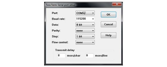
The serial port must be configured with:
• COM port number
• 115200 baud rate
• 8-bit data
• Parity none
• 1 stop bit
• No flow control
30/48 UM2242 Rev 3UM2242 Interacting with the boards
Serial port setup is illustrated in Figure 13.
Figure 13. Serial port setup
Once the UART terminal and the serial port are set up, press the board reset button (black).
Follow the indications on the UART terminal to upload Wi-Fi, cellular and Azure data. Those
data remain in Flash memory and are reused the next time the board boots.
UM2242 Rev 3 31/48
47Application examples UM2242
6 Application examples
6.1 Application description
The AzureXcubeSample application illustrates the various ways for an Azure device to
interact with an Azure IoT Hub.
The application connects to an Azure IoT Hub on basis of the credentials provided by the
user on the console.
6.2 Application setup
The setup of the application requires that the steps described from Section 6.2.3 to
Section 6.2.7 are executed in sequence.
6.2.1 Azure account creation
Create an Azure account if none is already available:
1. Go to the Azure web portal at https://portal.azure.com
2. Click on the link to create an account and follow the instructions
6.2.2 CLI setup
The Azure cloud can be managed either by its web portal or Azure command-line interface
(CLI).
For using Azure CLI, either install Azure CLI on a local personal computer, or use Azure CLI
from a cloud instance.
Local installation
1. Go to azure.microsoft.com
2. Click on Documentation, then SDK/tools, Management / Azure CLI / get started
(alternatively, open https://docs.microsoft.com/cli/azure)
3. Select the proper installation method for the local operating system
(MSI installer for Windows® for instance)
4. Install the CLI.
Once the CLI is installed, it is required to login to Azure using the following command:
$ az login
Azure cloud shell
1. Go to https://shell.azure.com/
2. Select Bash
a) A shell prompt opens in the browser window
b) Type the CLI commands in the browser window.
32/48 UM2242 Rev 3UM2242 Application examples
CLI IoT extension
In both cases, it is required to add the CLI IoT extension. Enter the following command in
the CLI (to be done only once):
az extension add --name azure-iot
6.2.3 Azure IoT Hub creation
An IoT Hub is required to interact with IoT devices.
To create an IoT Hub, it is possible to use either the Azure web portal or Azure CLI.
On the Azure web portal (https://portal.azure.com):
1. Login
2. Go to All Services / Internet of Things / IoT Hub service
3. Create an instance of IoT Hub
Alternatively using the Azure CLI:
$ az iot hub create -resource-group MyResourceGroup -name IoTHubName
6.2.4 Azure device creation
Web portal
On the Azure web portal:
1. Select the IoT Hub instance
2. Go to Explorers / IoT Devices
3. Create a device ("+ New")
Refer to Section 6.4: Authentication methods for the different kinds of device
authentications and the corresponding connection strings. Select the symmetric key
authentication type for a test.
Azure CLI
When using the Azure CLI, use the following commands:
First, connect to the Azure cloud:
• $ az login
Then create the device:
• $ az iot hub device-identity create -hub-name IoTHubName
-device-id DeviceID
The board MAC address can for instance be used as a device ID. A smart nickname can
also be chosen for convenience.
It is advised to keep a copy of the device connection string at hand since the
AzureXcubeSample application requests it on the console when it is launched for the first
time.
The next command allows to verify that the device twin status can be retrieved:
• $ az iot hub device-twin show -hub-name IoTHubName
-device-id DeviceID
UM2242 Rev 3 33/48
47Application examples UM2242
6.2.5 Application build and programming
Open the desired toolchain at
STM32CubeExpansion_Cloud_AZURE_Vx.y.z\Projects\\Applications\Cloud\
Azure\ and build the project.
Refer to Section 3.1: General description for information about the supported IDEs.
6.2.6 Firmware programming on the STM32 board
The binary file generated in STM32CubeExpansion_Cloud_AZURE_Vx.y.z\Projects \\Applications\Cloud\Azure\\Exe can be copied or dragged and dropped to the
USB mass storage location created when the STM32 board is plugged to the PC.
If the host is a Linux® PC, the STM32 device can be found in the /media folder with name
DIS_L4IOT. For example, if the created mass storage location is /media/DIS_L4IOT, then
the command to program the board with a binary file named my_firmware.bin is simply:
cp my_firmware.bin /media/DIS_L4IOT
Alternatively, the STM32 board can directly be programmed through one of the supported
development toolchains.
6.2.7 Application first launch
The board must be connected to a PC through the USB (ST-LINK USB port).
Open the console through a serial terminal emulator such as Tera Term (refer to Section 3.2:
Architecture).
On the console:
• For Wi-Fi-enabled boards, enter the Wi-Fi SSID, encryption mode and password
• For a cellular board, enter the cellular network credentials
• Set the device connection string (refer to Section 6.2.4), excluding enclosing quotes (")
• Set the TLS root CA certificates by copy-pasting the contents of
STM32CubeExpansion_Cloud_AZURE_Vx.y.z\Middlewares\Third_Party\azure-iot-
sdk-c\certs\usertrust_baltimore.pem. The device uses them to authenticate the remote
hosts through TLS.
Note: The AzureXcubeSample application requires that a concatenation of 2 CA certificates is
provided
1. For the HTTPS server that is used to retrieve the current time and date at boot time.(the
Usertrust certificate for the www.gandi.net server)
2. For the IoT Hub server (the Baltimore certificate)
The concatenated string must end with an empty line. This is usertrust_baltimore.pem.
After the parameters are configured, it is possible to change them by restarting the board
and pressing the user button (blue button) just after boot.
34/48 UM2242 Rev 3UM2242 Application examples
6.3 Application runtime
This section describes the life-cycle steps of the application that:
• Makes a single HTTPS request to retrieve the current time and date, and configures
the RTC
• Connects to the Azure IoT Hub
• Gets the status of the device twin
• Update its local properties (DesiredTelemetryInterval) from the desired
properties of the device twin
• Report the reported properties to the device twin (TelemetryInterval and
LedStatus)
Note: From this point, the user can get the twin status updates through command
$ az iot hub device-twin show
• Stays idle, pending on local user, or hub-initiated events
From this point the possible local user actions are:
• Single push on the user button: this action triggers a message publication to the IoT
Hub through a DeviceToCloud (D2C) message.
• Double push on the user button: this action starts or stops the message publication
loop. When the loop is running, the messages are published every
TelemetryInterval seconds.
Note: Each message publication is signaled by the user LED blinking quickly for half a
second.
The message content depends on the type of board used:
– B-L475E-IOT01A reports the sensor values and a timestamp
– P-L496G-CELL02, 32F413HDISCOVERY and 32F769IDISCOVERY only report a
timestamp
The implemented hub-initiated events are:
• CloudToDevice (C2D) message
The message is displayed on the board console
• C2D twin update
Used to change the telemetry publication period (that is the
DesiredTelemetryInterval parameter)
• C2D method
Used to call one of the following device methods:
– Reboot: reboots the board
– Hello: displays the message passed as parameter on the board console
• C2D action call
LedToggle can be called to make the user LED state toggle
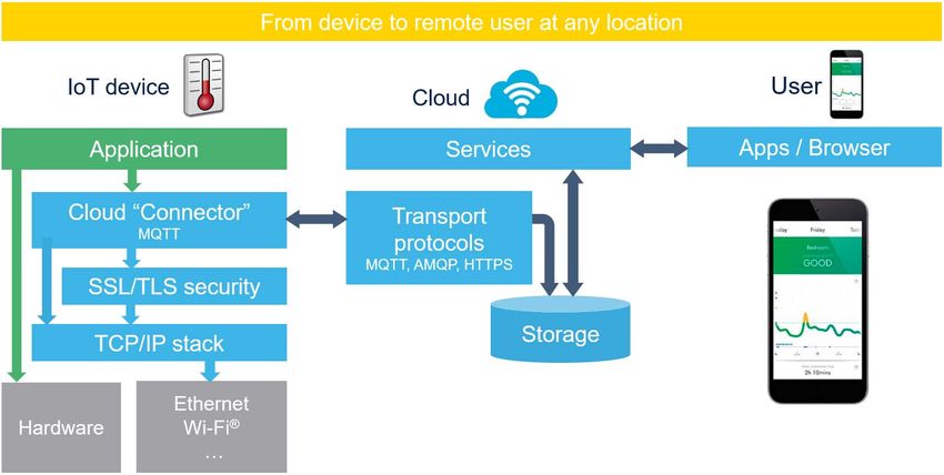
Figure 14 presents the runtime state flow.
UM2242 Rev 3 35/48
47Application examples UM2242
Figure 14. Runtime state flow
Init
[Single push]
[After a 5 s tempo] Connectivity configuration dialog SW reset
[Single push]
Store the file
[After a 5 s tempo] Azure® device configuration dialog
in Flash Slot#1
HTTP time limit
User application
[Single push] Firmware update dialog
download
[After a 5 s tempo]
[Single push]
DPS CA proof of possession dialog
Connect to the IoT hub
Receive and display the twin
state on the console
Process incoming messages, twin updates, and method calls
[Twin Update:: Disconnect from
[Single push] [Multiple push]
FwVersion] the IoT hub
1-time telemetry [After a 0.5 s tempo] Periodic telemetry
publication publication loop
[Device Method:: Disconnect from
Reboot] the IoT hub
[Multiple push]
[Device Method:: [Twin Update:: [Device Action::
Hello] DesiredTelemetryInterval] LedToggle]
Display the hello Change
Toggle the LED
message on the TelemetryInterval
console
Change Report
TelemetryInterval LedStatus
MSv63399V1
36/48 UM2242 Rev 3UM2242 Application examples
Table 4 lists the Azure CLI command lines for the user to trig hub-initiated events, and see
the results. The seven communication interfaces between the device and the cloud are
listed. The commands in the Way to call column uses the Azure CLI.
Table 4. Azure CLI command lines
Communication
Purpose Way to call, or format Comment
interface
az iot hub monitor-events -n
IoTHubName -d DeviceID
>
{
"mac": "",
"temperature": 31.39856,
"humidity": 29.069721,
"pressure": 997.830017,
The telemetry messages can
"proximity": 8190, be monitored if the user
Telemetry
D2C message "accX": -13, activates the publication by
data
"accY": -14, means of the user button on
"accZ": 1024, the board. Refer to Figure 14.
"gyrX": 1750,
"gyrY": -4970,
"gyrZ": 1470,
"magX": 170,
"magY": -180,
"magZ": 605,
"ts": "2017-06-07T15:14:22Z"
}
The Azure SDK prints an error
log because a C2D JSON
az iot device c2d-message send -n
command syntax is expected
C2D message Hello world IoTHubName -d DeviceId --data
by the message callback
'Hello world'
implementation on the device,
while a simple text is sent.
UM2242 Rev 3 37/48
47Application examples UM2242
Table 4. Azure CLI command lines (continued)
Communication
Purpose Way to call, or format Comment
interface
The Azure CLI and the hub
assume different payload
formats for the twin-update:
– At connection time, the full
string is received from the
hub: { "desired": {
"DesiredTelemetryInte
rval": x } }
– At runtime, when using
update-twin, it contains only
{
"DesiredTelemetryInte
rval": x }
The callback implementation
on the device is compatible
az iot hub device-twin update -n with both formats.
Change the
IoTHubName -d DeviceId --set '{ Still, it calls the JSON parser to
telemetry
C2D twin update "properties": { "desired": { identify the format.
publication
period
"DesiredTelemetryInterval": 6 } } If the Azure SDK “logtrace”
}' option was set, an error log
gets printed when the desired
key is not found.
This callback is also executed
automatically when the device
connects to the hub. If the user
has not set a
DesiredTelemetryInterva
l thanks to update-twin, a
JSON parsing error log is also
printed on the console.
On twin update, the new
TelemetryInterval is
automatically reported through
a D2C twin update.
38/48 UM2242 Rev 3UM2242 Application examples
Table 4. Azure CLI command lines (continued)
Communication
Purpose Way to call, or format Comment
interface
The twin-update is automatically performed by
the application running on the device.
The changes can be retrieved as follows:
az iot hub device-twin show -n
IoTHubName -d DeviceId
{
Report the "deviceId":"C47F510111A7",
telemetry "properties":{ Updates happen at connection
activation time, upon C2D twin update,
D2C twin update "desired":{
parameter, and upon C2D LedToggle
"DesiredTelemetryInterval":6,
and the LED call.
status },
"reported":{
"TelemetryInterval":6,
"LedStatusOn":false
}
}
}
az iot hub invoke-device-method -n
IoTHubName -d DeviceId --method-
name Reboot
Reboot, The “Reboot” implementation
C2D method
Hello az iot hub invoke-device-method -n has no parameters.
IoTHubName -d DeviceId -method-
name Hello -method-payload "{
\"msg\": \"World\" }"
LED toggle
device
For interoperability reasons,
command send DeviceId '{ "Name": "LedToggle",
C2D call the “Parameters” key must be
through a "Parameters": "" }'
given a value (any value).
C2D
message
D2C upload to
Unused - Not implemented.
blob
6.4 Authentication methods
6.4.1 Symmetric keys
When creating a device with the Azure IoT Hub web page, keep the default device creation
options:
• Authentication type: Symmetric key
• Auto-Generate Keys: checked
UM2242 Rev 3 39/48
47Application examples UM2242
After device creation, the keys and connection strings are visible in the Device details
window. Keep a copy of the connection string. It must be entered when configuring the
device the first time it is started.
6.4.2 X.509 self-signed certificate
Create a self-signed X.509 certificate and key for the device, for instance using the
OpenSSL tool:
openssl req -newkey rsa:2048 -nodes -x509 -sha256
-out X509Device_cert.pem -keyout X509Device_cert.key -days 365
-subj "/CN=X509Device"
Note: The "-subj" parameter must specify a common name ("/CN=") with the ID of the device
created in Azure.
Using the OpenSSL provided in Git for Windows Bash shell, it is needed to double the slash
in the common name. This is because Git for Windows interprets the single slash as part of
a directory name and translates it to Windows backslash. In such a configuration, the
previous command example becomes:
openssl req -newkey rsa:2048 -nodes -x509 -sha256
-out X509Device_cert.pem -keyout X509Device_cert.key -days 365
-subj "//CN=X509Device"
Azure requires a thumbprint of the certificate. It is a SHA1 hash on the device certificate
DER file (binary file, not PEM file).
Example with OpenSSL:
openssl sha1 X509Device_cert.der
If you only have certificate in PEM format, convert it to DER before doing the SHA1:
openssl x509 -in X509Device_cert.pem -outform DER
-out X509Device_cert.der
To create a device with the Azure IoT Hub web portal:
1. Go to the IoT Hub / IoT Devices Explorer page
2. Click on "+ Add"
3. Set the device creation options:
– Set Authentication type to "X509 self-signed"
– Provide the certificate thumbprint
When the device is started for the first time:
1. Enter the following connection string:
HostName=
IoTHubName.azure-devices.net;DeviceId=DeviceName;x509=true
2. Enter the root CA certificate
3. Enter the device's X.509 certificate and key
6.4.3 X.509 CA certificate
When creating a device with the Azure IoT Hub web page, set the device creation options:
• Authentication type set to “X509 CA-signed”
40/48 UM2242 Rev 3You can also read