Transverse Oscillating Bubble Enhanced Laser-driven Betatron X-ray Radiation Generation
←
→
Page content transcription
If your browser does not render page correctly, please read the page content below

Transverse Oscillating Bubble Enhanced Laser-driven Betatron X-ray
                                                 Radiation Generation
                                                             Rafal Rakowski,1, a) Ping Zhang,1, a) Kyle Jensen,1 Brendan Kettle,1 Tim Kawamoto,1 Sudeep Banerjee,1 Colton
                                                             Fruhling,1 Grigory Golovin,1 Daniel Haden,1 Matthew S. Robinson,1 Donald Umstadter,1 B. A. Shadwick,1 and
                                                             Matthias Fuchs1, b)
                                                             1
                                                              Department of Physics and Astronomy, University of Nebraska - Lincoln, Lincoln, Nebraska 68588,
                                                             USA
                                                             (Dated: 4 February 2022)
                                                             Ultrafast high-brightness X-ray pulses have proven invaluable for a broad range of research. Such pulses
                                                             are typically generated via synchrotron emission from relativistic electron bunches using large-scale facilities.
                                                             Recently, significantly more compact X-ray sources based on laser-wakefield accelerated (LWFA) electron
arXiv:2202.01321v1 [physics.acc-ph] 2 Feb 2022

                                                             beams have been demonstrated. In particular, laser-driven sources, where the radiation is generated by
                                                             transverse oscillations of electrons within the plasma accelerator structure (so-called betatron oscillations) can
                                                             generate highly-brilliant ultrashort X-ray pulses using a comparably simple setup. Here, we experimentally
                                                             demonstrate a method to markedly enhance and control the parameters of LWFA-driven betatron X-ray
                                                             emission. With our novel Transverse Oscillating Bubble Enhanced Betatron Radiation (TOBER) scheme, we
                                                             show a significant increase in the number of generated photons by specifically manipulating the amplitude of
                                                             the betatron oscillations. We realize this through an orchestrated evolution of the temporal laser pulse shape
                                                             and the accelerating plasma structure. This leads to controlled off-axis injection of electrons that perform
                                                             large-amplitude collective transverse betatron oscillations, resulting in increased radiation emission. Our
                                                             concept holds the promise for a method to optimize the X-ray parameters for specific applications, such as
                                                             time-resolved investigations with spatial and temporal atomic resolution or advanced high-resolution imaging
                                                             modalities, and the generation of X-ray beams with even higher peak and average brightness.

                                                 I.   INTRODUCTION                                                    However, routine operation of these sources requires
                                                                                                                   control over the source parameters, improvements in re-
                                                    Relativistic electron bunches can generate tunable             producibility and an increased laser-to-X-ray conversion
                                                 high-brightness X-ray pulses via synchrotron emission.            efficiency. The latter is of particular importance for a
                                                 The generation of electron beams with relativistic ener-          potential reduction in the peak power of the driver laser,
                                                 gies typically requires kilometer-scale facilities. Recently,     allowing for future sources with higher average flux at
                                                 significantly more compact X-ray sources have been                higher repetition-rate. Experiments have demonstrated
                                                 demonstrated using laser-wakefield accelerated (LWFA)             that the X-ray spectrum can be enhanced through the di-
                                                 electron beams1 . In particular, transverse (betatron) os-        rect interaction of the driver laser with the accelerating
                                                 cillations of electrons during acceleration in these plasma       electrons11 . Subtle laser characteristics, such as a pulse
                                                 structures can generate ultrashort high-brightness X-ray          front tilt were used to enhance the X-ray radiation12 , ma-
                                                 pulses via synchrotron emission (so called betatron ra-           nipulate the polarization13 and spectrum14 . An increase
                                                 diation) from a millimeter-scale interaction length2,3 .          in photon flux has been shown by using lasers with a
                                                 Laser-driven betatron sources have matured to an ex-              high pulse energy15–17 . A higher conversion efficiency
                                                 tent suitable for use in applications in many research            has been demonstrated by using clustered gas targets18
                                                 fields4–8 . Their high brilliance enables advanced imag-          and the transverse deflection of the injected and ac-
                                                 ing methods and due to the ultrashort X-ray pulse du-             celerated electron beam through transversally offsetting
                                                 ration and the intrinsic synchronization to the driving           the accelerating plasma structure by laser-electron-beam
                                                 laser, these sources are ideal tools to investigate ultra-        interactions19 or a modulated gas density profile20,21 .
                                                 fast dynamics9,10 . The comparably compact footprint                 Here we experimentally demonstrate a method to con-
                                                 and simple setup of these sources allows variable exper-          trol and significantly enhance the radiation characteris-
                                                 imental geometries, including the potential for multiple          tics by manipulating the amplitude of the betatron os-
                                                 time-synchronized X-ray pulses, at different wavelengths          cillation during the electron injection process. Our ap-
                                                 and at different incident angles for multi-probe diagnos-         proach is based on the evolution of the laser pulse into a
                                                 tics or single-shot tomography. This holds the promise of         highly asymmetric temporal shape (see Figure 4a). This,
                                                 widespread availability for applications in diverse fields        in combination with the longitudinal dynamics of the
                                                 ranging from medical imaging and structural biology to            accelerating plasma structure during a plasma-density
                                                 chemistry, physics and materials science.                         downramp, leads to controlled injection of copious elec-
                                                                                                                   trons from off-axis positions. These off-axis injected elec-
                                                                                                                   trons perform large-amplitude collective transverse be-
                                                 a) These   two authors contributed equally                        tatron oscillations during the subsequent propagation
                                                 b) mfuchs@unl.edu
                                                                                                                   inside the accelerating structure similar to those in a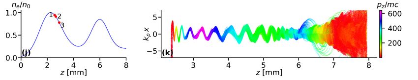
2

                                                                                                                                 3.5 x10
                                                                                                                                           19
permanent-magnet wiggler. We enable control over the                             Double-                                                         1.0 mm

                                                                                                            Gas Density [cm-3]
source parameters by splitting the source into three sec-                     peaked gas jet                                      3              2.0 mm

tions: (i) laser pulse shaping, (ii) electron injection and                                    electron                          2.5

(iii) a radiator section. These sections are implemented                                        beam                              2
                                                                                                                                 1.5
through a specifically tailored plasma density profile with                                      X-rays
                                                                                                                                  1
a double-peaked “M”-shaped structure (see inset Fig-
                                                                                                                                      -5 -4 -3 -2 -1 0 1 2 3 4 5
ure 1). In the first density peak the laser pulse is mod-                                                                                       Distance [mm]
ified into a highly asymmetric temporal shape through                                                 Electron spectrometer
self-evolution, which leads to an LWFA where electrons
                                                                         Laser
are injected from off-axis positions22 . The injection is
                                                                      polarization
controlled through a density downramp following the                       axis
first peak, leading to a copious amount of electrons that
are transversely injected with a longitudinally-correlated
phase. The injected electrons perform coherent betatron                                                                                                  X-ray
                                                                Laser                      Dipole         Al foil                          transmission
oscillations during a density depression and in a second                                                                                                camera
                                                                beam                       magnet                                              filters
density peak. The density depression between the peaks
and the density upramp of the second peak results in a          FIG. 1. Schematic of experimental setup. A high-power
nearly constant kinetic energy of the oscillating electrons     laser (red) is focused into a double-peaked “M” shaped gas
(see section IV), leading to an increased X-ray bright-         jet (blue). The laser evolution during the first density peak
ness. While for certain combinations of plasma densities        leads to off-axis electron injection during the following density
and laser intensities, transverse injection due to laser evo-   downramp. Subsequent large-amplitude betatron oscillations
lution also occurs in flat-top gas jets as was shown in         (yellow) cause emission of intense X-ray radiation (purple).
simulations23 , our tailored plasma density profile enables     The laser pulse is filtered out by a thin Al foil. The electron
control over these processes. Furthermore, it extends the       bunch is deflected and characterized using a dipole magnet
length over which betatron radiation is emitted due to an       spectrometer. The X-rays are measured using an absorption-
increased laser depletion length of the lower integrated        filter based spectrometer. The inset shows gas density mea-
                                                                surements for a distance of y=1 mm (green) and y=2 mm
plasma density compared to a flat-top profile.
                                                                (black) above the gas nozzle using a backing pressure of 250
   We were able to significantly enhance the generated          psi, the betatron experiments were performed at lower densi-
number of X-ray photons when compared directly to tar-          ties.
gets with a flat-top density profile under identical laser
conditions. In our concept, the coherent oscillations are
initiated close to the gas jet entrance, unlike other meth-     given by
ods where increased betatron oscillation amplitudes are                                               r
                                                                                                           γ
achieved by manipulating the already injected and ac-                                   K = rβ kp            ≈ γθ,                                                 (2)
celerated electron beam well into the gas jet20,21 or near                                                 2
the gas jet exit19 . This enables the control of multiple       with the betatron
degrees of freedom and the potential for additional sig-                            p amplitude rβ and the plasma
                                                                wavenumber kp = ne e2 /0 mc2 , where ne is the plasma
nificant enhancement through emission from many more            density, 0 the dielectric constant, e the electron charge,
betatron oscillation periods, further increasing the X-ray      m the electron mass and θ the maximum angle of the elec-
brightness and laser-to-X-ray conversion efficiency. We         tron velocity to the wiggler axis. For typical LWFA pa-
demonstrate that the X-ray properties can be controlled         rameters (where K  1) the number of emitted photons
through the manipulation of the betatron oscillation am-        per oscillation period and electron scales as Nph ∼ K.
plitudes by varying the plasma density profile.                 Both, Nph and Ecrit can be enhanced and controlled with
   Electrons in LWFAs operating in the self-injection           a larger betatron amplitude. Nph can also be increased
“bubble” regime24 perform transverse betatron oscilla-          with a higher electron beam charge and a greater number
tions during acceleration due to off-axis injection and a       of betatron oscillations, which we experimentally demon-
linear transverse restoring force25,26 . The transverse ac-     strate here.
celeration causes betatron synchrotron emission into a
narrow forward cone. The wiggler-like spectrum is char-
acterized by the critical photon energy, which is given         II.     EXPERIMENTAL SETUP AND METHODS
by27
                                                                   In the experiment, we compare the betatron emission
                               3     hc                         from different plasma density profiles, including an ap-
                     Ecrit =     Kγ 2 ,                  (1)
                               2     λβ                         proximately 7-mm-long double-peaked “M”-shaped pro-
                                                                file (see inset Figure 1) to flat-top density profiles with
with the electron relativistic factor γ, the betatron period    lengths of 4 and 6 mm using the same laser parame-
λβ , Planck’s constant h and the speed of light c. In the       ters. The M-jet has an effective plasma length of approx-
bubble regime, the electron deflection parameter K is           imately 4.4 mm consisting of two 2.2 mm wide peaks that
3
are interrupted by a density depression of 2.3 mm. The (a) Single shot
10 9
betatron source is driven by laser pulses with an energy 1.25
of 2.6 J on target, a FWHM duration of 34 fs, focused to "M" shape, y=1 mm
a 15 µm FWHM spot (see Figure 1). The laser-plasma "M" shape, y=2 mm
1
Photons/0.1%BW/sr/shot
interaction in the gas target causes the generation of rel- 6 mm flat-top
4 mm flat-top
ativistic electron bunches and intense X-ray pulses. The
laser pulse is blocked by a thin Al filter, while the electron 0.75
beam and X-rays above 2.7 keV are largely transmitted
(see Supplemental Material). The electrons are deflected
0.5
from the beam path using a dipole magnet (10.2 cm, 7.6
kG), which allows the simultaneous measurement of the
electron and X-ray spectra in a single shot. The elec- 0.25
tron beam spectrum and divergence are measured using
a phosphor screen located at a distance of 1.95 m from
0
the jet. The X-ray spectrum is diagnosed by the trans- 2 5 10 15 20 25 30
mission through a filter array consisting of Mylar, Al, V, Photon energy [keV]
Ti, Co, Fe, Zn, Cu, Zr, Mo, Pd, Ag, Sn and an Andor (b) 10
9 Five shot average
iKon-L SO X-ray CCD. The camera is shielded by a thin
Al foil to minimize any optical background contamina- 1 "M" shape, y=1 mm
tion. A Pb filter is used to determine any background. "M" shape, y=2 mm
Photons/0.1%BW/sr/shot
The filters were placed 1.9 m from the source and 0.75 6 mm flat-top
m from the detector. The beamline filters and the quan- 4 mm flat-top
0.75
tum efficiency of the detector limited the spectral obser-
vation range to 2.7-30 keV (see Supplemental Material).
The X-ray spectrum was deduced from least-square fit- 0.5
ting of the transmitted signal through each filter, taking
into account the transmission through additional beam-
line filters and the quantum efficiency of the detector 0.25
(for detailed description see Methods section below). To
account for the broad electron energy spread and the
changing energy of the emitting electrons during the ac- 0
2 5 10 15 20 25 30
celeration process, the spectral intensity was constrained Photon energy [keV]
to a sum of synchrotron spectra given by28
FIG. 2. Measured X-ray Spectra. (a) shows spectral inten-
N 2
d2 φ
X E 2 sity extracted from the filter transmission for a flat-top 4 mm
= Ai F2/3 [E/(2Ecrit,i )], (3) jet (red, dashed), a flat-top 6 mm jet (green, dotted) and the
dΩdE/E i
Ecrit,i
“M”-shaped jet for an interaction distance above the nozzle of
y1 = 1 mm (blue, solid) and y2 = 2 mm (cyan, dash-dotted)
where Ω is the solid angle, E the photon energy and F is for single shots. (b) shows a five-shot average. The fit param-
the modified Bessel function of the second kind. The am- eters for the five-shot average are given in Table I. The col-
plitudes Ai and critical energies Ecrit,i are fit parameters. ored shades represent the confidence bands obtained through
We limit our model to two sub-spectra (N =2) to avoid a statistical analysis of a large set of Monte-Carlo (MC) sim-
over-fitting the data while showing a significant improve- ulations. The confidence bands for the single shots indicate
ment over a single spectrum. A large set of Monte-Carlo a point-wise one-sigma band of bootstrapped datasets. The
(MC) simulations was used in a bootstrap method29 to confidence band for the averaged shots are obtained by un-
certainty propagation using the individual shot uncertainties
determine the confidence intervals via a statistical ap-
(see Methods section). The spectral observation range is lim-
proach (see Methods). ited to 2.7-30 keV (indicated through vertical gray shades)
due to filter transmission and the quantum efficiency of the
CCD camera.
III. EXPERIMENTAL RESULTS
A. X-ray Spectra The observed spectral intensity for the “M”-shaped pro-
file shows a clear enhancement in comparison to the other
For each jet the X-ray flux was optimized by adjusting jets (see Figure 2). Since the X-ray divergence exceeds
the plasma density and the jet position relative to the our detector solid angle of 11 mrad, we estimate the to-
laser focal plane. The brightest X-ray pulses with the 4 tal number of X-ray photons in a shot using the elec-
and 6 mm flat-top jets were generated for a plasma den- tron beam divergence. The total X-ray beam divergence
sity of 5×1018 cm−3 and with the M-jet for 1×1019 cm−3 . is given by the convolution of the single-electron emis-4
TABLE I. Gas jet comparison. The angular flux density is averaged over 5 shots for each jet. The total number of photons
is estimated from the angular flux density and the beam divergence. As the X-ray beam divergence exceeds the detector solid
angle, the horizontal X-ray beam divergence is inferred from the electron beam divergence and the vertical divergence from the
angular acceptance of the CCD detector (11 mrad). The averaged critical energies Ecrit,i and amplitudes Ai for each jet are
obtained by fitting an N = 2 sum of synchrotron spectra (equation 3) to the 5-shot averaged spectra. The uncertainties are
obtained by fitting a similar term to the 5-shot confidence bands.
Gas jet Angular flux density Beam divergence Estimated total number of photons Synchrotron spectra fits
[photons/sr/shot] [mrad2 ] [photons/shot] Ecrit,1 [keV] Ecrit,2 [keV]
(2.7 - 30 keV) (2.7 - 30 keV) (Amplitude A1 ) (Amplitude A2 )
4 mm +0.1 12 +0.2 8 4.4 +0.03
−0.6
+5.0
16.0 −5.1
flat-top 0.5 −0.1 × 10 24 × 11 1 −0.2 × 10
(0.6 −0.01 × 10 ) (1 −0.01 × 10⁸ )
+0.4 8 +0.2
+0.9 +2.5
6 mm 2.7 −0.4 15.6 −1.0
flat-top
+0.2
0.8 −0.2 × 10¹² 10 × 11 +0.2
1 −0.2 × 10⁸
(3.3 −0.7 × 10 ) (1.2 −0.7 × 10⁸ )
+0.9 8 +0.7
M-jet +0.3 +0.9
3.1 −0.3 12.7 −1.3
+0.2
1.5 −0.1 × 10¹² > 37 × 11 +0.6
> 6 −0.6 × 10⁸
y=1 mm, 65 psi (4.6 −0.7 × 10 ) (2.2 −0.3 × 10⁸ )
+0.8 8 +0.4
M-jet +0.5 +2.4
2.8 −0.4 15.0 −2.3
+0.2
1.0 −0.2 × 10¹² > 37 × 11 +0.9
> 4 −0.9 × 10⁸
y=2 mm, 90 psi (4.1 −0.5 × 10 ) (1.2 −0.8 × 10⁸ )
+0.5 8 +0.9
sion and the maximum electron beam deflection angle point during the interaction, which occurs for a jet that
inside the bubble. For a wiggler or betatron source, is longer than the laser depletion length and the dephas-
the X-ray divergence is dominated by the electron beam ing length (see section V). The experimentally measured
deflection28 , which in the LWFA bubble regime is equiv- values for the critical energies of the M-jet are signifi-
alent to the electron beam divergence after termina- cantly lower, which is a result of the limited sensitivity
tion of the plasma, i.e. θe,beam ≈ K/γ [27] . The X- of our spectrometer of 2.7-30 keV. Therefore, we expect
ray divergence in this case is approximately given by a substantial fraction of the generated betatron photons
θX,beam ≈ θe,beam ≈ K/γ. The electron beam generated to be outside our spectral detection limits, particularly
by the 6 mm jet has a horizontal divergence of 10 mrad, in case of the M-jet. Considering the photons outside our
whereas that from the M-jets are transversally clipped angular and spectral acceptance, we speculate the actual
by the spectrometer dipole magnet with an aperture of enhancement in photon number to be even significantly
37 mrad (see Figure 3). Using these values in the laser larger for the M-jet to compared to the flat-top profiles.
polarization dimension and the solid angle of the detec- We also demonstrate that we can control the X-ray pa-
tor in the other dimension as conservative lower limits, rameters by modifying the plasma density profile. To this
we estimate an increase in the number of X-rays gener- end we increase the distance between the laser-plasma
ated by the M- jet to be nearly one order of magnitude interaction point and the gas nozzle. As can be seen
compared to the 4 mm and the 6 mm round jets (see from the density measurement in Figure 1, the density
Table I). The sharp edges of the filter shadows indicate gradient and the peak-to-valley contrast can be modified
that the signal originates from a small source point and by changing the distance between the nozzle and the in-
is not due to Bremsstrahlung background from scattering teraction point. We compare our measurements with a
of the electron beam on the chamber walls. distance of y1 = 1 mm to y2 = 2 mm at similar plasma
densities by compensating the gas jet backing pressure.
We can estimate the critical photon energy from the The larger distance leads to a shift of the spectrum to-
electron beam parameters using equations (1) and (2) wards lower photon energies and an overall lower number
and the betatron period,
√ which in the bubble regime of photons (see Figure 2 and Table I).
is given by λβ = 2γ2π/kp [27] . Using the electron
beam divergence to estimate K, we obtain for the M-
jet a maximum Ecrit = 186 keV (θe = 37 mrad, γ= 1100,
ne = 1 × 1019 cm−3 ), for the 6 mm jet a maximum B. Electron Spectra
Ecrit = 5 keV (θe = 10 mrad, γ= 490, ne = 5×1018 cm−3 )
and for the 4 mm jet a maximum Ecrit = 12 keV (θe = We simultaneously measure the spectra of the electron
24 mrad, γ= 500, ne = 5 × 1018 cm−3 ). For the 4 mm bunches with angular resolution in the plane of the laser
jet, this estimate agrees reasonably well with the experi- polarization (see Figure 3). Although the spectra for all
mentally determined value. In case of the 6 mm jet, the the jets have a broad energy distribution, their charge
spectrum extends to higher photon energies well beyond and angular distributions are significantly different. In
the estimated critical energy. This is likely due to the X- particular, for the 6 mm flat-top density profile, we ob-
ray emission from electrons with higher energies at some serve the smallest beam divergence, lowest charge and5
CCD counts [arb. unit/MeV]
TABLE II. Comparison of the generated electron beam spec-
100 101 tra shown in Figure 3. The third column is the charge inte-
grated over an energy range, such that the lowest and highest
20 (a) 4 mm flat-top 20 (b) 6 mm flat-top
15 15
generated critical photon energies lie in our detection range
10 10
of 2.7-30 keV.
Divergence [mrad]
Divergence [mrad]
5 5 Gas jet Total charge Charge for generated X- Divergence
0 0
rays in detection limits
5 5
[CCD counts] [CCD counts] [mrad]
10 10
15
×105 ×105
15
20 20
4 mm
flat-top 9.0 8.5 24
800 550 400 300 250 200 800 550 400 300 250 200
Electron energy [MeV] Electron energy [MeV] 6 mm
flat-top 2.8 2.6 10
20 (c) M-jet, y=1mm 20 (d) M-jet, y=2mm
15 15 M-jet
7.6 3.7 > 37
10 10 y=1 mm
Divergence [mrad]
Divergence [mrad]
5 5 M-jet
0 0 4.8 1.7 > 37
y=2 mm
5 5
10 10
15 15
20 20
800 550 400 300 250 200 800 550 400 300 250 200
mrad acceptance angle. While the 4 mm flat-top and M-
Electron energy [MeV] Electron energy [MeV] jet both have large divergences, the total charge is signifi-
(e) 3000
cantly larger in case of the 4 mm jet. The maximum elec-
4 mm flat-top tron energy of the M-jet is significantly higher than that
2500 6 mm flat-top
M-jet y=1mm
of the 4 mm jet, which is significantly higher than that
Charge [arb. units]
2000 M-jet y=2mm of the 6 mm jet. Both, the 4 mm and the M-jet show en-
1500 ergetically narrow features with large divergence. These
1000
features indicate off-axis electron injection at a specific
position in the gas jet and the performance of coherent
500
betatron oscillations throughout the subsequent density
0 profile until termination of the gas jet. The large diver-
200 300 400 500 600 700
Electron Energy [MeV] gence, high charge and comparably low beam energy of
the 4 mm jet in combination with the comparably weak
FIG. 3. Electron Spectra Angularly-resolved in the Laser- X-ray emission indicates off-axis electron injection near
Polarization Plane. The electron spectra correspond to the the end of the gas jet during the density downramp. In
X-ray spectra of Figure 2a. The spectrum generated by the 4 case of the M-jet, the lower charge compared to the 4 mm
mm flat-top gas jet (a) has a large divergence and high charge jet, a higher maximum electron energy and stronger X-
(see Table II), while the divergence of the 6 mm jet (b) is more ray emission suggests off-axis injection during the density
typical for LWFAs operated at unmatched plasma densities. downramp of the first jet followed by subsequent accel-
The spectrum generated by the M-jet (c) extends to higher eration and X-ray emission over a longer distance and
energies with a significantly larger divergence. The observed possible loss of electrons due to the longitudinal bub-
electron spectra, in particular the structured narrow-band,
ble dynamics during the second density peak. Both, the
large-divergence features around 570 MeV agree well with the
coherent betatron oscillations observed in our particle in-cell lower maximum energy and lower charge of the 6 mm-
(PIC) simulations (see Figure 4). The divergence of the elec- long gas jet indicates electron injection and severe laser
tron beam is clipped by the 37 mrad angular acceptance of the depletion well before the end of the gas jet, which leads
dipole magnet. The spectrum of the M-jet using an increased to loss of electrons and decrease in beam energy due to
interaction distance from the gas nozzle (d) has a similarly dephasing. The stronger X-ray emission compared to the
large divergence but less charge. For better visibility of the 4 mm jet despite a lower charge indicates earlier electron
details, the plots are plotted on a logarithmic scale. A linear injection and betatron emission over a longer distance.
plot of the angular-integrated spectra is shown in (e). These dynamics are qualitatively well in agreement with
the dynamics that we observe in our our particle in-cell
(PIC) simulations (see section IV).
lowest peak energy (see Table II). In stark contrast, for The electron and X-ray parameters of the M-jet can be
the 4 mm flat-top and the M-jet we observe a signifi- controlled by the density profile. Specifically, the steep-
cantly larger divergence, which in case of the M-jet is even ness of the gradients in the modulated density profiles of
clipped by the angular acceptance of our dipole spectrom- the M-jets does not significantly impact the divergence
eter of 37 mrad. From the electron beam divergence it and maximum beam energy, but the profile with less
becomes clear that only a fraction of the generated pho- steep gradients decreases the accelerated charge, which
tons are observed by our X-ray camera that has an 11 has also been observed in numerical studies30 . Due to6
these specific dynamics for each jet, the measured elec- transversely oscillating high-density peak are injected
tron energies and charge after the termination of the jet into the accelerating fields at the back of the bubble. Be-
have only limited correlation with the X-ray emission. cause of the off-axis position, the electrons have a large
Nevertheless, the measured divergence is indicative of correlated transverse momentum when injected, which
the transverse electron momentum at the exit of the jet, leads to coherent large-amplitude transverse betatron os-
which in the bubble regime is mainly determined dur- cillations in the laser polarization plane as they propagate
ing the electron injection and largely unchanged over the (Figure 4k)22,23 . The longitudinally-correlated trans-
acceleration distance. verse momentum of the electrons can be seen in Figure 4i.
Despite a large transverse emittance integrated over the
whole bunch, the local transverse slice emittance is small.
IV. PARTICLE IN CELL (PIC) SIMULATIONS Near the plasma density minimum, the combination of
the laser evolution, increased plasma wavelength, lower
A. M-jet plasma fields and injected charge (beam loading) leads to
an elongated bubble super-structure, extending over mul-
tiple buckets (Figure 4h and i). As a result, the longitu-
We have performed two-dimensional PIC simulations
dinal bubble fields are highly suppressed and the kinetic
with EPOCH31 to better understand the electron dy-
energy remains nearly constant for a large fraction of the
namics of the betatron source. In the simulations, the
oscillating electrons over an extended spatial region along
gas jet was represented by a combination of two Gaus-
the jet. The quasi-constant electron energy and coherent
sian profiles that were fitted to the experimentally mea-
oscillations over a large distance can be seen in example
sured profile as shown in Figure 4. The peaks of the
trajectories of 1429 macro particles picked from a region
jet are 1 × 1019 cm−3 and 8.5 × 1018 cm−3 . The sim-
near the front of the electron bunch (Figure 4k). Due to
ulation domain extended to ±168 µm in the transverse
the lower bubble fields during the density depression at
direction with 1487 grid points and used a moving win-
the center of the M-jet, the electron beam experiences a
dow with 252 µm in the longitudinal direction with 8903
transverse expansion and a small increase in the betatron
grid points. The laser pulse, with a FWHM duration
oscillation amplitude around 3.5 - 5 mm20,34 . However,
of 35 fs, dimensionless vector potential a0 = 3.5 and
this is not the main cause of the large-amplitude oscilla-
Rayleigh length 363 µm, corresponding to an intensity
2 tions and enhanced betatron emission. During the sub-
of 2.62 × 10¹⁹ W/cm , was launched with a focus located
sequent density upramp of the second peak, the plasma
840 µm from the left hand boundary. A quiet start was
wavelength decreases and a single-bucket bubble struc-
used with macro-particles loaded with 16 macro-particles
ture is slowly reestablished. As a result, electrons per-
per cell −67 µm and 67 µm and with 1 macro-particle per
forming betatron oscillations are mainly confined to the
cell on the remainder of the domain. The time step was
first bucket, while electrons further back are lost (see
0.01588/ωp . The laser is polarized in the (x-z plane).
movie in SM). Due to the increase in the bubble phase
The simulations of the M-jet (movie in Supplementary
velocity, only a small fraction of electrons at the head
Material) show a significant laser pulse evolution dur-
slowly loose energy as they are propagating in a deceler-
ing the first density peak resulting in complex dynamics
ating phase, while a large fraction of electrons are acceler-
of the bubble boundary. This leads to electron injec-
ated and gain energies similar to that of the bunch front.
tion with specific initial conditions, in particular a large
This leads to high-brightness X-ray betatron emission
longitudinally-correlated transverse momentum. As a
from electrons that perform coherent large-amplitude be-
result, the injected electrons perform collective large-
tatron oscillations with almost constant kinetic energy
amplitude betatron oscillations during the subsequent
over a long propagation distance in the radiator section.
propagation (Figure 4). In the laser conditioning sec- Eventually, the laser pulse is nearly fully depleted and
tion during the first density peak, the laser pulse under- a bubble is driven by the injected electron bunch. The
goes substantial self-steepening and pulse compression, generated radiation for this density profile is significantly
which leads to a nearly step-like temporal field distribu- enhanced compared to flat-top gas jets. Both, the exper-
tion of the laser front (Figure 4a)32 . This field distribu- imentally observed X-ray and electron beam properties
tion causes a transverse asymmetry in the bubble shape agree well with the simulated kinematics of this process.
(Figure 4b)22 . The local depletion of the laser front33 re-
sults in oscillating positive and negative amplitudes of the
leading laser-field spike during further propagation. This
leads to a bubble asymmetry in the laser polarization B. Jet comparison
direction that changes direction in lock-step with the re-
versed sign of the leading field amplitude. As a result, the We have also simulated the comparison between the
bubble boundary and in particular the large plasma den- different jet density profiles. The charge in an area near
sity peak at the back of the bubble perform transverse os- the laser propagation axis (−15 < kp y < 15) and with a
cillations in the laser polarization plane (Figure 4). Due beam energy of γ > 20 is shown as a function of the laser
to the longitudinal bubble expansion during the density propagation distance (Figure 5). For the M-jet (blue),
downramp in the injection section, electrons from this the copious amount of charge that is injected during the7
Laser electric field Longitudinal electron Transverse electron
momentum momentum
Plasma density profile Sample electron trajectories
FIG. 4. Simulated betatron source dynamics (also see movie in SM). The evolution of the laser, bubble and the injected
electron beam is shown for different positions along the jet indicated in (j) as “1” (a)–(c), “2” (d)–(f) and “3” (g)–(i). The
laser is moving to the right (i.e. in positive z-direction). The asymmetric longitudinal laser pulse profile leads to a transverse
asymmetry in the bubble shape and off-axis electron injection during the density downramp (a)–(c). The field of the laser front
is depleted by a half cycle, leading to a field spike with opposite sign and an asymmetry into the opposite direction (d)–(f).
The controlled off-axis injection leads to a correlated transverse momentum distribution (c), (f), and (i) and coherent electron
oscillations in the laser polarization (x, z) plane. Near the plasma density minimum, the bubble evolves into a super-structure,
highly suppressing longitudinal accelerating fields (g)–(i). This leads to electron propagation with nearly constant energy as
can be seen from the trajectories of 1429 macro particles from near the head of the electron bunch (k). The laser electric field
Ex is normalized to E0 = mc2 kp /e, the longitudinal and transverse electron momenta (color coded) are normalized to mc and
the plasma density to the peak density n0 = 1 × 1019 cm−3 .
downramp after the first density peak has a maximum propagation through the jet, the laser self-evolves to a
near the density depression and is subsequently slowly highly asymmetric longitudinal shape similar to that of
lost during the second density peak as the laser gets the M-jet after the first density peak. Correspondingly,
depleted. For the 6 mm flat-top jet (green), charge is this leads to injection with a large transverse momentum.
injected after some propagation of the laser. The self-
focusing and self-evolution during this propagation leads
to an elongation of the bubble that results in further in- V. DISCUSSION
jection. During the subsequent propagation, charge is
slowly lost due to laser depletion. In contrast, for the
The measured X-ray and electron spectra indicate dif-
4mm flat-top jet, charge is mainly injected during the
ferent electron beam dynamics in the three jets. The 4-
density downramp at the exit of the jet. During the
mm flat-top jet generates electron beams with the highest8
×1016 ×1019 charge due to scattering out of the bubble. As the X-
M-jet 1.0 rays are generated over a longer distance throughout the
4 mm flat-top electron propagation distance, this leads to the emission
0.8 6 mm flat-top
0.8 of X-ray pulses with a higher flux and higher photons en-
ergies than what is expected from the measured electron
Beam Charge [C/m]
0.6 0.6 spectra at the jet exit.
Ne [cm 3]
The measured electron beams generated by the M-jet
0.4 have the largest divergence with a charge that is less than
0.4 that of the 4 mm-jet, while emitting the highest X-ray
flux. The observed electron and X-ray spectra agree with
0.2 0.2 the dynamics described in section IV, where the laser self-
evolves during the first density peak into a highly asym-
0.0 0.0 metric longitudinal shape. During the downramp of the
0 1 2 3 4 5 6 7 8 first jet, electrons are transversally injected and X-rays
z [mm] are mostly generated throughout the density depression
and the second density peak. Some of the injected charge
FIG. 5. Comparison of the charge for the different jets. The is likely lost during the interaction. The M-jet combines
simulation results of the charge near the laser propagation the features of the other jets, namely the transverse in-
axis (−15 < kp y < 15) with a beam energy of γ > 20 is jection of the 4 mm jet with the long emission length of
plotted as a function of the laser propagation distance z (solid
the 6 mm jet for X-ray generation that is enhanced by
line, left axis) for the density profiles (dashed line, right axis)
for the M-jet (blue), the 4 mm flat-top (red) and the 6 mm
the large betatron oscillation amplitude and by the den-
flat-top (green). sity profile that allows X-ray emission over an extended
length. While in the experiment it was not possible to
measure the effect of only one of the density peaks, the
4 mm jet (at lower density) shows a qualitatively similar
charge and a large divergence while emitting the weak-
behavior to that of only the first density peak. These
est on-axis X-ray flux. This indicates only a very limited
dynamics are consistent with simulations (see Figures 4
distance during which radiation is generated, which sug-
and 5).
gests that the electrons are injected near the jet exit at
the density downramp. This also agrees with an esti- Increasing the distance between the gas nozzle exit
mated acceleration distance of approximately 1 mm that and the laser interaction leads to a change in the plasma
is required to reach the observed electron energies for a density profile, in particular increasing the width of the
plasma density of ne = 5 × 1018 cm−3 . During the prop- peaks, decreasing the density slopes and decreasing the
agation through the jet, the laser significantly evolves peak-to-valley density ratio. In the experiment, this leads
and the large electron beam divergence suggests that the to a decrease in both, the injected charge and the on-
electrons are injected into a transverse asymmetric bub- axis X-ray flux. Simulations have shown that the slope
ble driven by such a pulse. After injection, the electrons of the density downramp has a strong effect on the elec-
emit radiation during approximately only 2 betatron os- tron beam parameters, in particular the amount of in-
cillations. The reasonable agreement of the X-ray spec- jected charge, the transverse emittance and the bunch
trum with the estimated critical energy deduced from the duration30 . This demonstrates that by varying the den-
measured electron bunch (see section III A) suggest that sity profile, it is possible to control the X-ray parameters.
most of the betatron radiation is emitted from electrons
with energies close to their measured spectrum at the
exit of the gas jet and that the electrons do not undergo VI. SUMMARY AND CONCLUSION
substantial dephasing.
The electron beams of the 6-mm flat-top jet have the We experimentally demonstrate the novel Transverse
lowest measured charge and smallest divergence while Oscillating Bubble Enhanced Betatron Radiation (TO-
generating a significantly higher X-ray flux than the 4- BER) generation regime that enables significant enhance-
mm jet particularly at lower photon energies. The mea- ment and control of laser-driven betatron radiation. In
sured X-ray spectrum extends well beyond the critical particular, we observe the generation of significantly
energy of 5 keV, estimated from the measured electron more X-ray photons compared to standard targets using
beam parameters. This suggests that the betatron radia- the same laser parameters. The X-ray source parame-
tion is mostly emitted during the interaction from within ters are enhanced and controlled through manipulating
the jet. In this case, electrons are continuously injected the amplitude of the transverse betatron oscillations by
into the bubble32 with a comparably large transverse mo- using a laser pulse with a highly asymmetric temporal
mentum that is however significantly smaller than in the shape that has a nearly step-like rise. This leads to off-
case of a self-evolved laser. The length of the jet is longer axis electron injection and coherent betatron oscillations,
than the dephasing and laser depletion length, which re- similar to those in a permanent-magnet wiggler. The
sults in a reduction of the electron energy and a loss of source can be decomposed into three sections: (i) laser9
pulse shaping, (ii) electron injection and (iii) radiation age correction. The X-ray spectra are extracted via a
generation. We demonstrate that this can be realized Forward-Fitting Monte Carlo (MC) method. As input
using a tailored plasma density profile. While longitudi- spectra, we assume a model constrained to a sum of syn-
nally tailored density profiles have been used to improve chrotron spectra given by equation (3). We use a sum
the electron beam quality35–37 , here we use a specifically of synchrotron spectra to account for the broad distribu-
tailored profile to significantly improve the X-ray beam tion and dynamics of electron energies, betatron ampli-
quality. In our proof-of-principle experiments we use a tudes and periods, which evolve during the interaction.
profile that consists of two peaks separated by a density We found that a sum of two spectra give significantly
depression. Here, the laser propagation in the first peak improved the fit over a single spectrum. Due to a corre-
leads to the asymmetric temporal pulse shape through lation of spectra with different critical energies, we limit
self-evolution. The off-axis electron injection is initiated the model to a sum of two spectra to avoid over-fitting
during the subsequent density downramp. The radiation the data. We iteratively randomly sample the multivari-
is mainly generated during the density depression and in ate parameter space (spectral amplitudes Ai and critical
the second density peak. We demonstrate that the X-ray energies Ecrit,i ) and forward-propagate the correspond-
pulse properties can be modified by changing the plasma ing spectra through each filter, including the beamline
density profile. and camera efficiency. We then compare to the experi-
The method can be used to readily optimize the X-ray mental data through a least-square fit and determine the
properties for specific applications. The plasma density best fit parameters by minimizing the χ2 value. For each
profile enables control of multiple X-ray properties, in- shot we perform the Forward-Fitting MC procedure on
cluding photon energy, number of generated photons and 2000 independent data sets. Shots with a χ2 per degree
spectral intensity. The method also has the potential to of freedom value of χ2 /N > 0.2 were excluded from the
adjust source properties, such as source size, beam di- analysis. We analyze this large parameter space sample
vergence and likely pulse duration to the requirements of to evaluate the goodness of the fit using the bootstrap
the specific application. Our concept has the potential method29 and to determine asymmetric point-wise con-
for even further enhancement and control of the X-ray fidence bands. Specifically, for each photon energy value
parameters and conversion efficiency. We expect that we find the 1-sigma distribution around our best fitting
the X-ray beams can be scaled to higher peak brilliance model, which is indicated as confidence bands in Figure 2.
through modifications in the plasma profile, by a higher- From the single shot statistics, we calculate the average
power driver laser or by using laser-generated electron spectra and confidence bands using a weighted statisti-
bunches as drivers38 to extend distance over which radi- cal approach. Shot-to-shot statistics are determined by
ation is emitted. Conversely, the plasma profile can also point-wise averaging and appropriate uncertainty propa-
be optimized to generate beams with higher average bril- gation considering the five shots with the highest signal
liance using lasers with lower peak power, operating at intensity. The energies of the fits were limited to a range
higher repetition rates. of 2.7 - 30 keV.
The control and enhancement of X-ray parameters is
of particular importance for the development of future
variable and tunable compact, high-repetition rate X-ray VIII. SUPPLEMENTARY MATERIAL
sources that can be readily used in applications.
The transmission through the filters used in the spec-
trometer and a movie of the particle-in cell (PIC) simu-
VII. METHODS lation can be seen in the Supplementary Material.
A. X-ray Spectrum Analysis
Data Availability Statement
We extract the X-ray spectra from the measured ab-
sorption filter transmission using a forward-propagation The data that support the findings of this study are
fitting method. To this end we first process the camera available from the corresponding author upon reasonable
images using a despeckling algorithm to eliminate hot request.
pixels, reduce the measured constant background given
by the Pb filter transmission and perform a background
gradient normalization using the direct beam in-between ACKNOWLEDGMENTS
filters to account for beam nonuniformities. Experimen-
tal measurements for each absorption filter material are This material is based upon work supported by the
extracted by averaging the transmitted signal over the Air Force Office of Scientific Research (AFOSR) un-
corresponding detector regions taking close to beam cen- der award number FA9550-15-1-0125. TK and BAS
ter. Standard deviations within these regions, prior to where supported but the US DoE under award number
image processing, are used for measurement uncertainty DE-SC0018363 and by NFS under award number PHY-
estimates with appropriate scaling to account for im- 1535678. The experiment was conducted at the Extreme10
Light Laboratory at the University of Nebraska-Lincoln. resonant betatron oscillations in a plasma wake,” Nature Physics
Part of this work was completed utilizing the Holland 7, 867–871 (2011).
12 C. Yu, J. Liu, W. Wang, W. Li, R. Qi, Z. Zhang, Z. Qin, J. Liu,
Computing Center of the University of Nebraska, which
M. Fang, K. Feng, Y. Wu, L. Ke, Y. Chen, C. Wang, Y. Xu,
receives support from the Nebraska Research Initiative. Y. Leng, C. Xia, R. Li, and Z. Xu, “Enhanced betatron radiation
Part of this research was performed using resources pro- by steering a laser-driven plasma wakefield with a tilted shock
vided by the Open Science Grid, which is supported by front,” Applied Physics Letters 112, 133503 (2018).
13 M. Schnell, A. Sävert, I. Uschmann, M. Reuter, M. Nicolai,
the National Science Foundation award #2030508.
T. Kämpfer, B. Landgraf, O. Jäckel, O. Jansen, A. Pukhov, M. C.
Kaluza, and C. Spielmann, “Optical control of hard x-ray po-
1 S.
larization by electron injection in a laser wakefield accelerator,”
Corde, K. Ta Phuoc, G. Lambert, R. Fitour, V. Malka, Nature communications 4, 2421–2421 (2013).
A. Rousse, A. Beck, and E. Lefebvre, “Femtosecond x rays from 14 S. P. Mangles, G. Genoud, S. Kneip, M. Burza, K. Cassou,
laser-plasma accelerators,” Reviews of Modern Physics 85, 1–48 B. Cros, N. P. Dover, C. Kamperidis, Z. Najmudin, A. Pers-
(2013). son, J. Schreiber, F. Wojda, and C. G. Wahlström, “Controlling
2 A. Rousse, K. T. Phuoc, R. Shah, A. Pukhov, E. Lefebvre,
the spectrum of x-rays generated in a laser-plasma accelerator by
V. Malka, S. Kiselev, F. Burgy, J.-P. Rousseau, D. Umstadter, tailoring the laser wavefront,” Applied Physics Letters 95 (2009).
and D. Hulin, “Production of a kev x-ray beam from synchrotron 15 S. Kneip, S. R. Nagel, C. Bellei, N. Bourgeois, A. E. Dangor,
radiation in relativistic laser-plasma interaction,” Phys. Rev. A. Gopal, R. Heathcote, S. P. Mangles, J. R. Marquès, A. Mak-
Lett. 93, 135005 (2004). simchuk, P. M. Nilson, K. T. Phuoc, S. Reed, M. Tzoufras, F. S.
3 S. Kneip, C. McGuffey, J. L. Martins, S. F. Martins,
Tsung, L. Willingale, W. B. Mori, A. Rousse, K. Krushelnick,
C. Bellei, V. Chvykov, F. Dollar, R. Fonseca, C. Huntington, and Z. Najmudin, “Observation of synchrotron radiation from
G. Kalintchenko, A. Maksimchuk, S. P. D. Mangles, T. Mat- electrons accelerated in a petawatt-laser-generated plasma cav-
suoka, S. R. Nagel, C. A. J. Palmer, J. Schreiber, K. T. Phuoc, ity,” Physical Review Letters 100 (2008).
A. G. R. Thomas, V. Yanovsky, L. O. Silva, K. Krushelnick, and 16 X. Wang, R. Zgadzaj, N. Fazel, Z. Li, S. A. Yi, X. Zhang, W. Hen-
Z. Najmudin, “Bright spatially coherent synchrotron x-rays from derson, Y.-Y. Y.-Y. Chang, R. Korzekwa, H.-E. H.-E. Tsai,
a table-top source,” Nat Phys 6, 980–983 (2010). C.-H. C.-H. Pai, H. Quevedo, G. Dyer, E. Gaul, M. Martinez,
4 S. Fourmaux, S. Corde, K. T. Phuoc, P. Lassonde, G. Lebrun,
A. C. Bernstein, T. Borger, M. Spinks, M. Donovan, V. Khudik,
S. Payeur, F. Martin, S. Sebban, V. Malka, A. Rousse, and J. C. G. Shvets, T. Ditmire, and M. C. Downer, “Quasi-monoenergetic
Kieffer, “Single shot phase contrast imaging using laser-produced laser-plasma acceleration of electrons to 2 gev,” Nature Commu-
Betatron x-ray beams,” Optics Letters 36, 2426 (2011). nications 4, 1988 (2013).
5 S. Kneip, C. McGuffey, F. Dollar, M. S. Bloom, V. Chvykov,
17 F. Albert, N. Lemos, J. L. Shaw, B. B. Pollock, C. Goyon,
G. Kalintchenko, K. Krushelnick, A. Maksimchuk, S. P. D. Man- W. Schumaker, A. M. Saunders, K. A. Marsh, A. Pak, J. E.
gles, T. Matsuoka, Z. Najmudin, C. A. J. Palmer, J. Schreiber, Ralph, J. L. Martins, L. D. Amorim, R. W. Falcone, S. H. Glen-
W. Schumaker, A. G. R. Thomas, and V. Yanovsky, “X-ray zer, J. D. Moody, and C. Joshi, “Observation of Betatron X-
phase contrast imaging of biological specimens with femtosecond Ray Radiation in a Self-Modulated Laser Wakefield Accelerator
pulses of betatron radiation from a compact laser plasma wake- Driven with Picosecond Laser Pulses,” Physical Review Letters
field accelerator,” Applied Physics Letters 99, 093701 (2011). 118 (2017).
6 J. M. Cole, J. C. Wood, N. C. Lopes, K. Poder, R. L. Abel,
18 L. M. Chen, W. C. Yan, D. Z. Li, Z. D. Hu, L. Zhang, W. M.
S. Alatabi, J. S. Bryant, A. Jin, S. Kneip, K. Mecseki, D. R. Wang, N. Hafz, J. Y. Mao, K. Huang, Y. Ma, J. R. Zhao, J. L.
Symes, S. P. Mangles, and Z. Najmudin, “Laser-wakefield accel- Ma, Y. T. Li, X. Lu, Z. M. Sheng, Z. Y. Wei, J. Gao, and
erators as hard x-ray sources for 3D medical imaging of human J. Zhang, “Bright betatron X-ray radiation from a laser-driven-
bone,” Scientific Reports 5, 1–7 (2015). clustering gas target,” Scientific Reports 3 (2013).
7 B. Mahieu, N. Jourdain, K. Ta Phuoc, F. Dorchies, J. P. Goddet, 19 C. F. Dong, T. Z. Zhao, K. Behm, P. G. Cummings, J. Nees,
A. Lifschitz, P. Renaudin, and L. Lecherbourg, “Probing warm A. Maksimchuk, V. Yanovsky, K. Krushelnick, and A. G. R.
dense matter using femtosecond X-ray absorption spectroscopy Thomas, “High flux femtosecond x-ray emission from the
with a laser-produced betatron source,” Nature Communications electron-hose instability in laser wakefield accelerators,” Phys.
(2018). Rev. Accel. Beams 21, 041303 (2018).
8 A. E. Hussein, N. Senabulya, Y. Ma, M. J. V. Streeter, B. Kettle,
20 B. Guo, Z. Cheng, S. Liu, X. N. Ning, J. Zhang, C. H. Pai, J. F.
S. J. D. Dann, F. Albert, N. Bourgeois, S. Cipiccia, J. M. Cole, Hua, H. H. Chu, J. Wang, and W. Lu, “Enhancement of laser-
O. Finlay, E. Gerstmayr, I. G. González, A. Higginbotham, D. A. driven betatron x-rays by a density-depressed plasma structure,”
Jaroszynski, K. Falk, K. Krushelnick, N. Lemos, N. C. Lopes, Plasma Physics and Controlled Fusion 61, 035003 (2019).
C. Lumsdon, O. Lundh, S. P. D. Mangles, Z. Najmudin, P. P. 21 M. Kozlova, I. Andriyash, J. Gautier, S. Sebban, S. Smartsev,
Rajeev, C. M. Schlepütz, M. Shahzad, M. Smid, R. Spesyvtsev, N. Jourdain, U. Chulagain, Y. Azamoum, A. Tafzi, J.-P. God-
D. R. Symes, G. Vieux, L. Willingale, J. C. Wood, A. J. Shahani, det, K. Oubrerie, C. Thaury, A. Rousse, and K. Ta Phuoc,
and A. G. R. Thomas, “Laser-wakefield accelerators for high- “Hard x rays from laser-wakefield accelerators in density tailored
resolution x-ray imaging of complex microstructures,” Scientific plasmas,” Phys. Rev. X 10, 011061 (2020).
Reports 9, 3249 (2019). 22 E. N. Nerush and I. Y. Kostyukov, “Carrier-envelope phase ef-
9 K. Ta Phuoc, R. Fitour, A. Tafzi, T. Garl, N. Artemiev, R. Shah,
fects in plasma-based electron acceleration with few-cycle laser
F. Albert, D. Boschetto, A. Rousse, D.-E. Kim, A. Pukhov, pulses,” Phys. Rev. Lett. 103, 035001 (2009).
V. Seredov, and I. Kostyukov, “Demonstration of the ultrafast 23 Y. Ma, L. Chen, D. Li, W. Yan, K. Huang, M. Chen, Z. Sheng,
nature of laser produced betatron radiation,” Physics of Plasmas K. Nakajima, T. Tajima, and J. Zhang, “Generation of femtosec-
14, 080701 (2007). ond γ-ray bursts stimulated by laser-driven hosing evolution,”
10 F. Albert and A. G. R. Thomas, “Applications of laser wakefield
Scientific Reports 6, 30491 (2016).
accelerator-based light sources,” Plasma Physics and Controlled 24 A. Pukhov and J. Meyer-ter Vehn, “Laser wake field acceleration:
Fusion 58, 103001 (2016). the highly non-linear broken-wave regime,” Applied Physics B:
11 S. Cipiccia, M. R. Islam, B. Ersfeld, R. P. Shanks, E. Brunetti,
Lasers and Optics 74, 355–361 (2002).
G. Vieux, X. Yang, R. C. Issac, S. M. Wiggins, G. H. Welsh, M. P. 25 I. Kostyukov, E. Nerush, A. Pukhov, and V. Seredov, “Elec-
Anania, D. Maneuski, R. Montgomery, G. Smith, M. Hoek, D. J. tron self-injection in multidimensional relativistic-plasma wake
Hamilton, N. R. Lemos, D. Symes, P. P. Rajeev, V. O. Shea, J. M. fields,” Phys. Rev. Lett. 103, 175003 (2009).
Dias, and D. A. Jaroszynski, “Gamma-rays from harmonically11 26 S. Kalmykov, S. A. Yi, V. Khudik, and G. Shvets, “Electron self- mas,” Physics of Plasmas 3, 2047–2056 (1996). injection and trapping into an evolving plasma bubble,” Phys. 34 K. Ta Phuoc, E. Esarey, V. Leurent, E. Cormier-Michel, C. G. R. Rev. Lett. 103, 135004 (2009). Geddes, C. B. Schroeder, A. Rousse, and W. P. Leemans, “Beta- 27 E. Esarey, B. A. Shadwick, P. Catravas, and W. P. Leemans, tron radiation from density tailored plasmas,” Physics of Plasmas “Synchrotron radiation from electron beams in plasma-focusing 15, 063102 (2008). channels,” Phys. Rev. E 65, 056505 (2002). 35 C. G. R. Geddes, K. Nakamura, G. R. Plateau, C. Toth, 28 H. Onuki and P. Elleaume, eds., Undulators, Wigglers and their E. Cormier-Michel, E. Esarey, C. B. Schroeder, J. R. Cary, Applications (Taylor & Francis, London, 2003). and W. P. Leemans, “Plasma-density-gradient injection of low 29 W. H. Press, S. A. Teukolsky, W. T. Vettering, and B. P. Flan- absolute-momentum-spread electron bunches,” Physical Review nery, NUMERICAL RECIPES The Art of Scientific Computing Letters 100, 215004 (2008). Third Edition (CAMBRIDGE UNIVERSITY PRESS, 2007). 36 A. V. Brantov, T. Z. Esirkepov, M. Kando, H. Kotaki, V. Y. By- 30 H. Ekerfelt, M. Hansson, I. Gallardo González, X. Davoine, and chenkov, and S. V. Bulanov, “Controlled electron injection into O. Lundh, “A tunable electron beam source using trapping of the wake wave using plasma density inhomogeneity,” Physics of electrons in a density down-ramp in laser wakefield acceleration,” Plasmas 15, 073111 (2008), https://doi.org/10.1063/1.2956989. Scientific Reports 7 (2017), 10.1038/s41598-017-12560-8. 37 Z. Zhang, J. Liu, W. Wang, W. Li, C. Yu, Y. Tian, R. Qi, 31 T. D. Arber, K. Bennett, C. S. Brady, A. Lawrence-Douglas, C. Wang, Z. Qin, M. Fang, J. Liu, K. Nakajima, R. Li, and M. G. Ramsay, N. J. Sircombe, P. Gillies, R. G. Evans, Z. Xu, “Generation of high quality electron beams from a quasi- H. Schmitz, A. R. Bell, and C. P. Ridgers, “Contempo- phase-stable cascaded laser wakefield accelerator with density- rary particle-in-cell approach to laser-plasma modelling,” Plasma tailored plasma segments,” New Journal of Physics 17, 103011 Physics and Controlled Fusion 57, 113001 (2015). (2015). 32 S. Y. Kalmykov, A. Beck, S. A. Yi, V. N. Khudik, M. C. 38 J. Ferri, S. Corde, A. Döpp, A. Lifschitz, A. Doche, C. Thaury, Downer, E. Lefebvre, B. A. Shadwick, and D. P. Umstadter, K. Ta Phuoc, B. Mahieu, I. A. Andriyash, V. Malka, and “Electron self-injection into an evolving plasma bubble: Quasi- X. Davoine, “High-brilliance betatron γ-ray source powered by monoenergetic laser-plasma acceleration in the blowout regime,” laser-accelerated electrons,” Phys. Rev. Lett. 120, 254802 (2018). Physics of Plasmas 18, 056704 (2011). 33 C. D. Decker, W. B. Mori, K. Tzeng, and T. Katsouleas, “The evolution of ultra-intense, short-pulse lasers in underdense plas-
You can also read