The Effectiveness of Dimples on a NACA Airfoil: A Numerical Investigation Conducted via an Independent Study
←
→
Page content transcription
If your browser does not render page correctly, please read the page content below

Paper ID #32963

The Effectiveness of Dimples on a NACA Airfoil: A Numerical
Investigation Conducted via an Independent Study
Miss Jenna Elizabeth Stolzman, Grand Valley State University
     Jenna Stolzman is a senior mechanical engineering undergraduate student at Grand Valley State Univer-
     sity. She will begin her Ph.D. in mechanical engineering at University of Michigan in fall 2021. She also
     serves on the leadership committee for GVSU’s chapters of American Society of Mechanical Engineers
     and Society of Women Engineers.
Dr. Sanjivan Manoharan, Grand Valley State University
     Sanjivan Manoharan is an Assistant Professor at the School of Engineering at Grand Valley State Uni-
     versity. He received his BSE and MSE degrees in Aerospace Engineering at Embry-Riddle Aeronautical
     University and his Ph.D. in Mechanical Engineering at the University of Cincinnati. His research inter-
     ests are in the thermo-fluids area and also focuses on promoting graduate education among undergraduate
     students via research collaborations.

                              c American Society for Engineering Education, 2021
The Effectiveness of Dimples on a NACA Airfoil: A Numerical Investigation
                    Conducted via an Independent Study
Abstract

This paper integrates research and education in an effort to enhance the critical thinking skills of
an undergraduate Mechanical Engineering student while also promoting graduate engineering
education. To achieve this, a three-credit undergraduate independent study was conducted where
the research topic of interest was mitigating boundary layer separation, a topic covered in the
undergraduate Fluid Mechanics course. Delaying boundary layer separation to improve airfoil
aerodynamic performance can be achieved by passive techniques which include the use of vortex
generators, rough patches, uniform suction/blowing, and dimpled surfaces. Dimpled surfaces
have been known to generate swirl by the creation of vortices thereby energizing the flow. It is
believed that the generation of vortices and swirl can be used to mitigate boundary layer
separation thus improving lift, reducing drag, and delaying stall for an airfoil. Dimples were
chosen since conflicting observations exist in the literature, and this would be a good challenge
for the student. This paper numerically investigates the effectiveness of dimples on a NACA
4414 airfoil while also addressing the conflicting observations available in literature and the
thought process of the student.

First, an extensive literature review was conducted by the student to observe the use of dimpled
surfaces with respect to airfoils. The various configurations pertaining to a single dimple shape,
size, and axial location and their efficacy were considered. Following this, the NACA 4414
airfoil was numerically analyzed using the Computational Fluid Dynamics software, ANSYS
FLUENT. Parametric studies were then conducted to determine the optimal configuration of a
single dimple and multiple dimples. At this stage, the student conducted the investigation
independently without any guidance from the instructor. Different geometrical shapes, sizes,
placement along the airfoil, and multiple arrangements were all considered. The designs were
driven by fundamental fluid mechanics principles that were applied by the student. This forced
the student to think outside of the box and develop critical thinking ability. The project was a
challenge for the student as the findings were in direct contrast with many other researchers.
While reporting the results is important, of equal importance is the understanding and
articulating the physics behind the flow behavior. Through this independent study, the student
contributed to the gaps in knowledge, enhanced the critical thinking ability, learned how to
conduct thorough literature review and improve technical writing skills. The student’s academic
growth via this study was remarkable, and the student was highly appreciative of the various
lessons learned while also deciding to take on more research by pursuing graduate education.
Introduction

The aerodynamic performance of bodies interacting with fluids has been extensively researched
within the aviation industry where the primary focus is increasing lift and decreasing drag to
obtain maximum efficiency. This idea is especially of importance with respect to airfoils. While
the primary goal is to increase performance, a phenomenon called boundary layer separation
works in opposition. Boundary layer separation occurs as a result of an adverse pressure gradient
causing the flow to detach from the object or surface and subsequently decreasing performance.
Mitigation of boundary layer separation is critical to increase aerodynamic performance, and
given its heavy practical nature, this area was chosen as the vehicle to synergize research and
education for this student, who also represents a minority group in Engineering. This
independent study was deemed valuable by the Mechanical Engineering Curriculum Committee
and was used to replace a technical elective from the student’s undergraduate curriculum.
Independent studies have existed for many years and are very valuable to enrich a student’s
undergraduate education [1,2]. Scott [3] argues that in fact universities must assume
responsibility when organizing independent studies for their students. Such studies also help
students identify if research is for them and subsequently begin preparations for their graduate
degree while also providing in-depth technical knowledge in a particular field.

The remaining part of this section gives the required background and was written by the student.
The associated fluid mechanics principles were covered in the course, and the student was able to
connect them to the airfoil. The portions that are in quotation throughout the paper are written by
the student.

“The boundary layer is the region of fluid near a surface where a velocity gradient naturally
exists due to the viscosity of the fluid [4]. Due to no-slip boundary condition, the velocity of the
fluid that is adjacent to the surface of the body is zero. The velocity of the fluid eventually
reaches the free stream velocity as the vertical distance increases (Fig. 1). The vertical distance
from the surface to the point where the local velocity is 99% of the free stream velocity is
defined as the boundary layer thickness [4].

                          Figure 1: Boundary layer thickness illustration
For the flow over an airfoil, due to its curvature, the incoming fluid will reach a maximum
velocity, and up until this point it witnesses a favorable pressure gradient (high to low pressure).
Beyond this point, the fluid must return to ambient pressure and is now undergoing an adverse
pressure gradient (low to high pressure) (Fig. 2). There is flow reversal as a result of the adverse
pressure gradient resulting in air being drawn in at the airfoil trailing edge and momentum of the
forward flow decreasing.

If the available kinetic energy is not sufficient to overcome the adverse pressure gradient, the
fluid may leave the surface of the airfoil, thus separating from the body [4-6]. The point at which
this occurs is called the boundary layer separation point. Early boundary layer separation will
create a wake region that contains a large number of vortices (Fig. 3) resulting in an increase in
pressure drag and a decrease in lift. Therefore, the larger the wake zone, the lower the
aerodynamic efficiency.

                              Figure 2: Velocity profile along airfoil

At high angles of attack, boundary layer separation can occur prematurely due to an aggressive
angle coupled with the curvature of the airfoil. At high angles, the maximum velocity magnitude
increases yielding a larger adverse pressure gradient and wake zone; Bernoulli’s principle states
that an increase in velocity results in a decrease in pressure. Beyond a certain angle, the lift will
drop drastically due to the boundary layer separation, and at this point, the airfoil will stall. The
angle at which the lift is maximum is called the stall angle or critical angle of attack.

                      Figure 3: Wake zone and separation point on an airfoil

Since a decrease in lift performance is highly undesirable, researchers have discovered
techniques to increase aerodynamic performance. The objective is to energize the flow enough to
combat the adverse pressure gradient and push the point of separation further downstream. This
will delay boundary layer separation and decrease the wake zone thus increasing aerodynamic
performance. The two branches of techniques used to mitigate boundary layer separation and
increase performance are divided into active and passive. Active techniques require an energy
input, are generally costlier and require maintenance; however, they can be controlled by
switching the device on and off thus making them useful during take-off or landing. Some
examples of active devices include steady/unsteady suction or blowing, oscillatory motions,
acoustic excitations, use of synthetic jets, and other control methods. Passive techniques do not
require an energy input, cannot be controlled once placed on the airfoil, but provide a
technologically and economically efficient solution. Passive techniques include the use of vortex
generators, gurney flaps, fixed slots, riblets, and leading-edge perturbations such as tubercles and
bumps [7]. Another form of a passive technique that has been researched within the past decade
to improve aerodynamic efficiency is the use of dimples on an airfoil. Dimples are most
commonly used on a golf ball to decrease drag. The dimples work to create a thin turbulent
boundary layer that clings to the ball's surface. This allows the fluid (i.e. air) to follow the
curvature of the golf ball’s surface farther along the back side, thus decreasing the wake zone
and improving performance [8]. Drawing on this theory, the same idea could be used on airfoils
with certain modifications. This passive technique will be the primary focus of this paper.”

The student conducted independent research on the various techniques and decided to pursue a
passive method which is relatively easier to implement given the compressed timeline. The entire
project had to be concluded in three months and involved the following: revision of associated
fluid mechanics principles, research on boundary layer separation mitigation techniques,
thorough literature review on selected passive technique, learning the required software,
verification and validation of numerical model, parametric investigation to determine optimal
configuration, and authoring technical papers. This independent study was a three-credit hour
course that replaced a required technical elective for the student. Meetings were held every
Wednesday and lasted for a maximum of three hours. Since dimples have proven to be effective
on golf balls, it is also of interest to test their efficacy on airfoils to enhance aerodynamic
performance by energizing the flow and delaying boundary layer separation. There has been
some contradictory research with respect to the optimal location, size and geometry of the
dimple(s) on an airfoil. An aim of this paper will be to address these ambiguities and test the
effectiveness of a dimpled airfoil while filling in certain gaps in knowledge.

Literature Review

“There have been numerous research efforts to test the efficacy of dimples on an airfoil, and the
literature is broad with researchers testing dimpled airfoils both experimentally and numerically.
Within the numerical studies, two-dimensional and three-dimensional airfoils have been tested,
and from researcher to researcher, there appears to be some contradictory results. Livya et al. [9]
and Kaushik et al. [10] both conducted a numerical analysis of a symmetric 3-D NACA 0018
airfoil with dimples. Livya et al. [9] tested semi-sphere, hexagon, cylindrical, and square
geometries and a compound arrangement of semi-sphere followed by a square. It was found that
the semi-spherical inward dimple performed the best. Kaushik et al. [10] tested 13 inward and
outward semi-spherical dimples placed spanwise at 24% axial chord length. Similar to Livya et
al. [9], the inward semi-spherical dimple provided an increase in lift; however, the outward

dimple also showed an increase in lift. In both cases (inward and outward), the drag also
increased which was different to what was reported by Livya et al. Srivatsav [11] conducted a 2-
D and 3-D analysis also on a dimpled NACA 0018 airfoil. The 2-D study found that outward
dimples provided a reduction in drag while the 3-D study resulted in an outward round dimple
providing a boost in lift, but a subsequent undesirable increase in drag. Moving forward with
symmetrical airfoils, Saraf et al. [12] conducted a 2-D numerical study on a NACA 0012 airfoil
with the dimple location varying from 10%, 25%, 50% and 75% chord length. It was found that
the dimple located at 75% chord length performed the best. Singh et al. [13] conducted an
experimental dimple study using a NACA 0011 airfoil with various dimple geometries and sizes.
The three modifications they tested were: (1) outward hexagonal dimples of 8 mm, 10 mm, and
12 mm; (2) semi-cylindrical dimples with sizing of 25 x 22 x 10 mm (small), 25 x 14.5 x 7 mm
(medium), and 25 x 11 x5 mm (large); and (3) continuous strips with sizing of 305 x 22 x 10
mm, 305 x 14.5 x 7 mm, and 305 x 11 x 5 mm. They concluded that a medium sized semi-
cylindrical outward dimple placed at 66% chord length performed best. Binci et al. [14] studied
the flow field of a NACA 64-014A symmetric airfoil with spherical shaped dimples in the
laminar regime. They concluded the dimples reduce the laminar separation bubble and pressure
drag.

Stolt et al. [15] performed an experimental study on a NACA 0015 airfoil with dimples placed
on the top and bottom toward the leading edge of the body. Contrasting with previous studies, it
was concluded that the dimples may cause significant power loss and would not prevent
boundary layer separation. Zulkefli and MohdNur [16] also experimentally tested the efficacy of
inward and outward dimples, but did so on a NACA 4415 airfoil. The dimples were semi-
spherical in shape with a radius of 2.5 mm and were placed at 50% chord length. Similar to Stolt
et al., [15] both inward and outward dimples performed poorly for both pre and post-stall in
terms of lift. However, the inward dimple showed some promise at low-to-moderate angles of
attack with a slight boost in lift-to-drag ratio. Mustak et al. [17] also experimentally evaluated
the performance of a dimpled NACA 4415 airfoil. The spherical shaped dimples tested were of
inward and outward configurations. It was determined that either configuration delayed the stall
angle by 4 degrees while exhibiting superior lift performance and a reduction in drag at all angles
of attack. Tej et al. [18] numerically studied dimple effects on varying 3-D NACA airfoils,
specifically 0012, 1412, 2412, 3412, and 4412 airfoils. They concluded that a teardrop shaped
inward dimple placed at 70% chord length was more effective on a more heavily cambered
airfoil; however, the study was only completed at 0 degrees angle of attack. Table 1 summarizes
all aforementioned research efforts.

It is clear that there are contrasting results in literature with regard to the performance of a
dimpled airfoil. While most researchers observe an enhancement in performance with the
addition of a dimple, it is not clear where the dimple should be placed axially or what the optimal
geometry/size of the dimple should be. Furthermore, the current literature mainly focuses on the
lift and drag values instead of the flow physics of the dimple subjected to an adverse pressure
gradient. To clarify the inconsistencies in literature, and to better understand the flow physics of
the dimple, a numerical study has been conducted for a cambered airfoil. Various dimple shapes,
sizes, and locations in 2-D have been studied. The following section describes the numerical
setup and turbulence model chosen for this study. While this paper highlights the 2-D results,
detailed 3-D studies were also conducted, and those results are discussed in a separate paper.”

Table 1: Summary of research efforts [9-18]

Numerical Setup

“A cambered 2-D NACA 4414 airfoil was selected as the baseline. The coordinate points of the
profile were generated using an online airfoil generator [19]. The maximum camber was 4.3%
located at 40% chord length; the airfoil’s thickness was 14% chord length and 153 points were
generated in space. Using the coordinates, the profile of the airfoil was modeled in SolidWorks
with a 100 mm chord length (Fig. 4), and ANSYS Fluent was used for all Computational Fluid
Dynamic (CFD) simulations.

                 Figure 4: NACA 4414 2-D base airfoil modeled in SolidWorks

The boundary conditions include a low Reynolds number of 2x10⁵ (close to transition) which
corresponds to an inlet velocity of 30 m/s. The outlet was a pressure outlet with 0 gage pressure.
The top/bottom sides of the domain were set as symmetry while the airfoil set as a wall with no-
slip. Figure 5 provides the boundary conditions along with the refined mesh.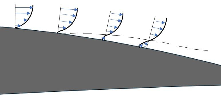
Figure 5: Boundary conditions of baseline airfoil with mesh

Since CFD is a course that is not taught at the undergraduate level at most institutes, the
instructor first taught the student basic CFD application and then provided supplemental videos
to enhance meshing techniques. Once the student was familiar with the intended software
(ANSYS FLUENT), the next phase of turbulence modeling was discussed. This is an advanced
topic taught in graduate courses, so the student was encouraged to read about the various models,
clarify doubts, and test various models for the baseline airfoil to observe performance. The
turbulence modeling choice along with model validation written by the student are given below.

Various turbulence models were tested such as Spalart Allmaras (SA, 1 eqn), k-ε (2 eqn), k-⍵
SST (2 eqn), k-⍵ SST with gamma transport equation transition (2 eqn), k-kl-⍵ (3 eqn), and
transition SST (4 eqn). While the SA turbulent model is one of the most commonly used models
for aerodynamic applications due to its ease of convergence, it can be unpredictable in the
laminar-turbulent transition regime. Therefore, it was not considered for our study. The k-ε
turbulence model has challenges predicting flows with adverse pressure gradients such as the
airfoil that will be studied. The transition k-kl-⍵ and transition SST turbulent models were able
to capture the transition zone from laminar to turbulent, but underpredicted the wake zone and so
were not pursued further. As a result, the turbulence models were narrowed to k-⍵ SST and k-⍵
SST with gamma. The k-⍵ SST model is known in general to perform accurately with boundary
layers that possess adverse pressure gradients [20]. Both models were tested and were found to
perform extremely similar in terms of lift and drag (Fig. 6 and 7). However, the k-⍵ SST with
gamma model was able to predict the laminar separation bubble (LSB). Since the study is being
conducted at a Reynolds number that is within the transition zone, it is of importance to capture
the LSB. For this reason, the k-⍵ SST with gamma turbulence model was chosen for the
remainder of the study.

Figure 6: Lift vs. AoA for k-⍵ SST and k-⍵ SST with gamma turbulence models

       Figure 7: Drag vs. AoA for k-⍵ SST and k-⍵ SST with gamma turbulence models

The 2-D baseline airfoil was then analyzed at various angles of attack using the aforementioned
turbulence model and the results were compared to those from experiments conducted in house
(Fig. 8). The CFD study and experimental run agree extremely well both pre and post-stall,
proving the efficacy of the k-⍵ SST with gamma turbulence model. The stall angle for the CFD
study and the experimental run was 10 degrees.
Figure 8: Comparison of 2-D and experimental NACA 4414 base airfoil lift coefficient

A grid independence study was then completed with the mesh size ranging from very coarse to
very fine. It was decided that the mesh was refined enough when the percent change in lift
coefficient values, from one mesh to the next, was less than half a percent. Upon convergence,
the final mesh chosen had 219,836 cells. The same mesh settings were used throughout the
course of this study. Of course, for the dimpled cases, the cell counts increased due to extra
inflation layers that were needed to accurately capture the flow in and around the dimples.”

The validation stage was critical to make the student understand that CFD results by themselves
mean nothing without experimental verification. Once the validation stage was concluded, the
student began the independent research with minimal guidance to develop the critical thinking
ability. Parametric studies consisting of various design modifications driven by fluid mechanics
principles were tested to understand the effect the dimple has on the surrounding flow structure.
Rather than try random shapes, the student was encouraged to reason out if the intended shape
would boost performance before simulating it. Furthermore, even graduate students do not fully
comprehend CFD results as they are impressed by the various multicolored contours and are less
interested in understanding if the obtained results align with theory or not. To avoid this, the
instructor consistently questioned the student on the validity of the numerical results by
analyzing various streamlines and contour plots. The following 2-D dimple study section gives a
glimpse into the thought process of the study and was written by the student.

Two-Dimensional Dimple Study

Single Dimple Chord Length Variation

“A single dimple was created with a 2.5 mm diameter and 0.5 mm depth. This yields a 20%
depth-to-diameter (d/D) ratio and the dimple was tested from 10%-75% chord length at 5%
increments. Figure 9 shows the dimples at 10% and 75% chord length for illustration purposes.
The dimples were tested at a 14-degree angle of attack (stall angle was 12 degrees) to determine
post-stall performance. Table 2 summarizes the percent increase of the lift-to-drag ratio at
various chord lengths, with respect to the base airfoil.
Figure 9: Single dimple at 10% chord length (top) and 75% chord length (bottom)

       Table 2: Percent increase in L/D of airfoil at 14 degrees with respect to base airfoil

Clearly, there is a significant boost in aerodynamic performance due to the single dimple and is
especially significant when the dimple is placed after 30% chord length. Figure 10 displays
aerodynamic performance (lift to drag ratio) of the dimple at different locations along the chord
length. It appears that, at a higher angle of attack (AoA), the dimple location is not significant,
especially on and after 30% chord length. Meaning, there is a large and similar boost in
performance due to the dimple at any given chord length. This is in contradiction with certain
previous research efforts that gave a defined optimal location for the dimple on an airfoil.
Figure 10: Effect of dimple location on L/D value at 14 degrees
The dimple at 35% and 65% chord length were then tested at a wide range of angles to observe
any benefit at low-to-moderate angles of attack, and the results are shown in Figure 11. It
appears that the dimple gives the largest boost in performance at higher angles of attack.
Furthermore, it can be seen that the dimple location does have an effect on aerodynamic
performance at low angles of attack which is in contrast to the higher angles of attack. The
dimple placed at 65% chord performs slightly better than the baseline airfoil at low angles of
attack, while the dimple at 35% chord shows a significant reduction in performance. However,
either dimple location gives a similar boost in L/D at high angles of attack. This dependence on
position at high and low angles of attack has not been discussed in the literature.”
Figure 11: Comparison of dimpled and base airfoil for wide range of angles of attack
Following this finding, rather than focus on just the numbers like many studies have done, the
student was encouraged to probe more and understand why this phenomenon could behappening. More independent research was required and the student’s findings are reported
below.
“The dimple location on the 2-D airfoil matters at low angles of attack, but does not matter at
high angles of attack in terms of performance. This is shown in the Turbulent Kinetic Energy
(TKE) plots at 0 degrees (Fig. 12). For the base airfoil, the flow is given sufficient time and
distance to transition to turbulence downstream marked by an increase in TKE. At 0 degrees,
when the dimple is placed at 35% chord length, it appears there is enhanced mixing but the flow
does not reattach at the aft edge of the dimple. As a result, the flow struggles in its transition to
turbulence and begins to slow down aft of the dimple, resulting in reduced performance. The
dimple placed at 65% chord lies in the transition to turbulent region, resulting in no noticeable
boost in performance, but has a marked increase in TKE at the aft edge of the dimple due to the
reattachment of the flow.
Figure 12: TKE contour plots at 0 degrees. Top: base airfoil; Mid: 35% chord dimples; Bottom:
65% chord dimples
At higher angles of attack, since the flow separates prematurely, it is unclear as to how the
dimple placed at 65%, which falls in the separation zone, produces enhanced performance. To
better understand the unusually significant boost in lift at high angles of attack, velocity contour
and vector plots were created for the 2-D airfoil at 14 degrees angle of attack. As shown in the
velocity contour plot, the wake zone is reduced when the dimple is placed at either 35% or 65%
chord length (Fig. 13). As a result, there is a boost in performance. A closer look at the vector
plots for the dimple placed at 65% chord shows reversed flow entering the dimple, creating swirl
(low pressure) due to the geometry, then mixing with the free stream (Fig. 14). The mixed flowpulls the free stream closer to the airfoil’s surface due to a vertical pressure gradient which then
results in the reduced wake zone seen in Figure 13.
Figure 13: Velocity contour plots at 14 degrees. Top: base airfoil; Mid: 35% chord dimples;
Bottom: 65% chord dimples
Figure 14: Velocity vector plot of dimple placed at 65% chord at 14 degrees
The significant boost in lift at high angles of attack is suspicious, especially for the dimple
placed within the wake zone, past the separation point (at 65% chord length). It is surprising that
a dimple placed within the wake region increases the aerodynamic performance. These results
indicate that further analysis would need to be completed in 3-D since the effects that are
occurring are three-dimensional; the wake zone is inherently a 3-D phenomenon. Thus, the 2-D
studies in the literature that simply report lift and drag coefficient values might need to be
reevaluated as looking at the flow structure is far more crucial.”
Single Dimple Geometry Variation“Since prior research mainly focused on semi-circular shaped dimples, it is of interest to test
various geometries to observe any benefit. Perhaps the sharp edges of a rectangular or triangular
cross section will assist in transitioning the flow to turbulent thus delaying boundary layer
separation more than the semi-circular geometry. Three geometries were tested: rectangular,
triangular and trapezoidal. The overall depth ratio of 20% was used, similar to the previous
section. The dimensions for each geometry can be seen in Figure 15. The geometries were tested
at 35% and 65% chord length at a high angle of attack and compared to the baseline airfoil and
previously done semi-circular geometry. The results are summarized in Table 3. It appears the
rectangular geometry placed at 35% chord length outperformed the competing geometries
significantly; however, when the varying dimple geometries were placed at 65% chord length,
the percent increase in L/D did not vary significantly from geometry to geometry.
(a) (b)
(c)
Figure 15: Dimple with (a) rectangular geometry; (b) triangular geometry; (c) trapezoidal
geometry
Table 3: Percent increase in L/D due to various geometries at 14 degrees compared to base airfoilThe rectangular geometry at 35% and 65% chord length was then tested at 0 degrees angle of
attack. The results are summarized in Table 4. The aerodynamic performance did not change
significantly as a result of the geometric modification at a low angle, i.e. both semi-circular and
rectangular performed poorly by roughly the same amount. However, at a low angle, it appears
that the location of the dimple does matter, which is consistent with our conclusion from the
previous section. When the dimple, regardless of geometry, is placed farther upstream (toward
the leading edge), the performance drops. When the dimple is placed toward the trailing edge,
there is a slight boost in performance, but it is not very significant.
Table 4: Percent increase/decrease in L/D due to various geometries at 0 degrees compared to
base airfoil
These results were similar to the previous sections where the performance drops when the dimple
is placed toward the leading edge at low angles of attack. At high angles of attack, the dimple
location and geometry have no significant impact on L/D; the performance of the airfoil
increases significantly no matter the shape or location. Again, this is contradictory with prior
research, but more studies conducted in 3-D are required to fully understand the effects of the
dimple and will be reported in a separate paper.”
Single Dimple Depth Variation
“Since the semi-circular dimple placed at 65% chord length yielded similar performance to the
rectangular shape at low and high angles of attack, it was chosen to study the effects of varying
the depth ratio. The 35% chord length placement was not considered as it performed poorly for
low angles of attack. A d/D (diameter to depth) ratio of 10% and 75% (Fig. 16) was tested at 0-
and 14-degrees angle of attack; the previous sections dimples were tested at a 20% d/D.
(a) (b)
Figure 16: (a) 10% d/D ratio; (b) 75% d/D ratioThe results are summarized in Table 5. It appears that at low angles of attack, a lower depth ratio
gives better performance while at high angles of attack, a higher d/D ratio yields better
performance, but not by much. There is a reduction in performance at low angles of attack when
the d/D ratio is increased to 75%. To more clearly understand why this is occurring, TKE plots
were created for the various depth ratios of the dimple located at 65% chord length (Fig. 17). For
the 10% depth ratio, there is a marked increase in TKE near the leading edge of the dimple, but
the energy fades out toward the aft edge. However, for the 20% depth ratio, the increase in TKE
occurs right at the aft edge of the dimple and is relatively sustained when compared to the other
cases. It appears the 75% d/D dimple does not provide the marked increase in TKE as seen in the
10% or 20% depth ratio; this resulted in reduced performance.
Table 5: Percent increase/decrease in L/D due to various d/D ratios at 65% chord length
compared to base airfoil
Figure 17: TKE contour plots for dimples at 65% chord length at 0 deg AoA. Top: 10% d/D
ratio; Mid: 20% d/D ratio; Bottom: 75% d/D ratio.At a high angle of attack, the 75% d/D ratio dimple placed at 65% chord length appears to have performed similarly to the dimple with a 20% d/D ratio. The vector plot for the 75% depth ratio shows reversed flow entering the dimple, creating swirl due to its geometry, then becoming re- routed to mix with the free stream (Fig. 18). Subsequently, the wake zone is reduced, resulting in an increase in performance. This is similar to what is seen for the 20% d/D dimple in Fig. 14. Figure 18: Velocity vector plot of 75% depth ratio dimple placed at 65% chord at 14 degrees Based on this study, the varying depths had an effect on performance only at low angles of attack. As the depth increased, the performance dropped. At high angles of attack, there was a boost in performance due to the dimple regardless of the depth ratio. Again, this is suspicious considering the dimple is placed within the wake region and subsequent 3-D studies need to be conducted to obtain more information regarding the flow structure. Extensive 3-D studies are currently being done.” As is evident, the student focused more on comprehending the flow pattern and behavior rather than the absolute lift and drag values itself as reported by most authors. The thought process logically proceeded and was driven by questioning results, using fundamental principles to explain flow behavior, and conducting independent research to better understand certain flow patterns. It should be noted that only a small portion of the results are provided here as the 3-D simulations and other various multiple staggered geometries are currently under investigation. Throughout the study, several questions were asked to justify the findings which forced critical thinking development. While this was the intended effect of undertaking this independent study, an unintended positive side effect was also observed. This study produced results that were in direct contradiction to many existing studies, and this caused some initial hesitancy for the student as the general idea was that existing studies must be true. Over time, the student realized that results in the literature may be challenged provided correct physics is used. For example, it was found that one researcher had used inappropriate boundary conditions resulting in artificial acceleration of the flow which then yielded enhanced lift and drag performance due to wake zone reduction. This realization improved the confidence and left the student wanting to learn more. Independent studies can be used as vehicles to promote synergy between research and education, enhance critical thinking of interested students, allow students to decide if research and subsequent enrollment in graduate school is right for them, and also promote professional development of the faculty member. It is recommended that higher education institutes promote independent studies to improve their visibility while faculty, especially at teaching institutes, use it as a vehicle to continue to engage in fundamental research for professional development. The paragraph below is the reflection written by the student at the culmination of this study.
“Through this independent study, I gained invaluable experience with applying theory to a real-
life scenario through modifying/improving the dimple(s) based on the flow structure studied
using computational methods. Upon commencement of the study, I had limited experience using
CAD software and no experience in executing CFD simulations. There was a steep learning
curve throughout the first month as I learned how to effectively use both software.
Simultaneously, I performed a deep literature review on the efficacy of dimples on an airfoil
surface. Although the literature review resulted in contradicting results, it allowed for a baseline
and elementary understanding of how the dimple should perform on a cambered surface with
respect to lift and drag values. Some past research efforts showed the optimal location of a
dimple to be toward the leading edge of the airfoil while other researchers found it to be toward
the trailing edge. The first component of the 2-D parametric study to find the optimal location of
the single dimple resulted in interesting results. Contrary to literature, the lift of an airfoil was
found to be significantly improved due to a dimple regardless of its chord location, at a high
angle of attack. Subsequent investigation into the flow structure in and around the dimple was
conducted to obtain the full picture. This allowed for further understanding and as to the true
behavior of a dimple on a cambered surface. Furthermore, my critical thinking ability has greatly
improved as a result of the close examination of the dimples effect on an airfoil. Studying the
dimples behavior and using basic fluid mechanics theory prompted me to adjust the geometry to
obtain an optimal condition. As the study progressed, I was able to independently complete and
assess increasingly complex CFD simulations while managing the data in a succinct manner. I
felt much more confident in my decision-making process and, as a result, felt comfortable
conducting the study with less supervision. I became proficient in CAD and CFD software as
well as data management. I was challenged throughout the course of this study to consistently
ask myself ‘why’, then use the data that was given to explain the behavior. Reflecting on the
study as a whole, there were certain aspects that could be improved. For one, in the beginning of
the study, I struggled to perform the CFD simulations independently and felt I needed constant
direction from my professor. However, as it progressed, I learned to take risks and the
importance of trial-and-error when learning this complicated software. Another aspect that could
be improved is being diligent in truly understanding prior research before conducting the study.
At times, when I was stuck, I would recheck prior studies and catch a detail that I had missed
during my literature review. If I were to restart this independent study, I would be more careful
in taking detailed notes when evaluating prior research efforts. This study has resulted in an
enhanced confidence in my abilities as a student and researcher. It has since sparked great
interest and inspired me to continue research within the fluid mechanics realm by pursuing
graduate studies in Mechanical Engineering with a focus in fluid mechanics.”

Conclusions

Multiple 2-D studies were conducted to observe the efficacy of dimples on a NACA 4414 airfoil.
The results were compared with literature and found to be contradicting. According to existing
literature, the optimal location of the dimple to increase performance varies from researcher to
researcher. In our study, however, the location of the dimple did not seem to matter at high
angles of attack. That is, there was a significant boost in L/D when the dimple was placed
anywhere along the chord length of the airfoil, especially after 30% chord length. This was
further explained by a velocity vector plot where the dimple placed downstream displayed
reversed flow entering the dimple, swirling within the dimple, then re-routing and mixing with
the free stream. This created a reduced wake zone and subsequent enhanced performance. At a
low angle of attack, the dimple placed further downstream performed better, as demonstrated by
an increase in TKE at the aft edge of the dimple. The shape of the dimple was then varied to
observe any additional improvement. A rectangular, triangular, and trapezoidal shaped dimple
was tested at 35% and 65% chord length at a high angle of attack. The results were similar to the
semi-circular shaped dimple where the location did not have a significant effect on L/D. The
rectangular shaped dimple slightly outperformed the others and was subsequently tested at a low
angle of attack. Again, at a low angle of attack, the dimple performed better when placed
downstream, regardless of the geometry. The TKE plots for the various geometries (rectangular,
triangular and trapezoidal) showed similar results as the semi-circular shape. Next, the depth
ratio of the semi-circular shaped dimple located at 65% chord length was varied and tested at
10% d/D and 75% d/D ratios. At a low angle of attack, the 75% depth ratio showed a reduction
in performance. This was shown in the TKE plot where the large depth provided no enhancement
to the turbulent energy. At a high angle of attack, all dimples showed a significant increase in
performance with the 75% depth ratio dimple slightly outperforming the others. Again, a
velocity vector plot was used to further explain the physics behind the boost in performance.

Overall, at a high angle of attack, a dimple placed anywhere along the chord significantly
increases performance of the NACA 4414 2-D airfoil. At low angles of attack, a dimple placed
further downstream is favorable and can be explained through TKE plots. While prior research
simply reported lift and drag values, our study attempted to understand the flow structure of the
dimple through velocity contours, velocity vectors and TKE plots. While our study was
contradictory with prior research, the current study was executed in 2-D only. Since the flow
over an airfoil is a 3-D phenomenon, further studies need to be conducted to obtain a more
thorough understanding of the flow structure and subsequent effectiveness of a dimpled airfoil.
This independent study was very beneficial for the student in sharpening critical skills and
sparking an interest in graduate school.

References
[1] Chickering, A. W. and Gamson Z. F., “Seven Principles for Good Practice in Undergraduate
Education,” American Association for Higher Education, 1987, pp. 3-7.
[2] Welch, R. W. and Evans, M. D., “Undergraduate Independent Study Research Projects,” ASEE
Annual Conference and Exposition, Salt Lake City, UT, 2004.
[3] Scott, R. A., “Independent Study in the Undergraduate College,” Cornell University—New
York Hospital School of Nursing Faculty Forum on Independent Study, December, 1973.
[4] Munson, B., Young, D., Okiishi T., Fundamentals of Fluid Mechanics, Wiley, 5th ed., 2006.
[5] Pritchard, P. and Mitchell, J., Introduction to Fluid Mechanics, Wiley, 9th ed., 2015.
[6] Cengal, Y. and Cimbala, J., Fluid Mechanics Fundamentals and Applications, McGraw Hill,
1st ed., 2006.
[7] Genc, M. S., Koca, K., Demir, H., and Acikel, H. H., “Traditional and New Types of Passive
Flow Control Techniques to Pave the Way for High Maneuverability and Low Structural Weight
for UAVs and MAVs,” IntechOpen, 2020.
[8] Veilleux, T., “How do dimples in golf balls affect their flight?” Scientific American, retrieved
4      December    2020.     https://www.scientificamerican.com/article/how-do-dimples-in-golf-
ba/#:~:text=Dimples%20on%20a%20golf%20ball,the%20size%20of%20the%20wake.
[9] Livya, E., Anitha, G., and Valli, P., “Aerodynamic Analysis of Dimple Effect on Aircraft
Wing,” International Journal of Aerospace and Mechanical Engineering, Vol. 9(2), 2015, pp. 350-
353.
[10] Kaushik, V., Mahore, M., and Patil, S., “Analysis of Dimpled Wing of an Aircraft,”
International Journal of Engineering Development and Research, Vol. 6(3), 2018.
[11] Srivastav, D., “Flow Control over Airfoils using Different Shaped Dimples,” International
Conference on Fluid Dynamics and Thermodynamics Technologies, Singapore, 2012.
[12] Saraf, A. K., Singh, M. P., Chouhan, T. S., “Effect of Dimple on Aerodynamic Behaviour of
Airfoil,” International Journal of Engineering and Technology, Vol. 9(3), 2017, pp. 2268-2277.
[13] Singh, D., Gajghat, R. H., Manik, M. K., “Experimental Investigation To Examine The Effect
of Shape And Size Of Dimple At Suction Surface Of Aerofoil”, International Journal of Scientific
& Technology Research, Vol. 8(12), 2019, pp. 521-534.
[14] Binci, L., Clementi, G., D’Alessandro, V., Montelpare, S., and Ricci, R., “Study of the flow
field past dimpled aerodynamic surfaces: numerical simulation and experimental verification,”
35th UIT Heat Transfer Conference, Ancona, Italy, 2017.
[15] Stolt, A. J., Ullah, A. H., and Estevadeordal, J., “Study of Leading-Edge Dimple Effects on
Airfoil Flow Using Tomographic PIC and Temperature Sensitive Paint,” Fluids, Vol. 4(4), 2019.
[16] Zulkefli, N. F., Samsudin, W. K. F. W., and Nur, N. M., “Dimples Effectiveness on Naca4415
Airfoil,” International Journal of Advanced Science and Technology, Vol. 29(6), 2020, pp. 203-
207.
[17] Mustak, R., Uddin, MD. N., and Mashud, M., “Effect of different shaped dimples on airfoils,”
Proceedings of the International Conference on Mechanical Engineering and Renewable Energy,
Chittagong, Bangladesh, 2015.
[18] Tej, G. R., Rajasai, B., and Anurang, S., “Variation of Behaviour of Dimples on Aircraft
Wings,” IEEE Aerospace Conference, Big Sky, Montana, 2016.
[19] “NACA       4-digit   airfoil   generator,”   Airfoiltools,   retrieved   8 November 2020.
http://airfoiltools.com/airfoil/NACA4digit
[20] Argyropoulos, C. D. and Markatos, N. C., “Recent advances on the numerical modelling of
turbulent flows” Applied Mathematical Modelling, Vol. 39, pp. 693-732.
You can also read