The 4G robotic UAV - Parrot
←
→
Page content transcription
If your browser does not render page correctly, please read the page content below
The 4G robotic UAV
Cover illustration: a computational fluid dynamic (CFD) view of ANAFI Ai, showing the static
    pressure distribution on the drone (right of the image), and highlighting the air vortices around the
                                                         drone, at full forward speed (left of the image).

2                                                                                                     v1.4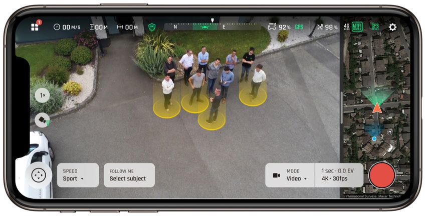
Table of contents
A naturalist remark.................................................................................................................................... 5

Flight performances ................................................................................................................................. 6
   Key features ............................................................................................................................................................................. 6
   A cool drone ............................................................................................................................................................................. 6
   Aerodynamic performances ............................................................................................................................................ 6
   Actuators and aerodynamics........................................................................................................................................... 7
   Sensors....................................................................................................................................................................................... 8
   Autopilot ................................................................................................................................................................................... 10
   Autonomous flight ............................................................................................................................................................... 12
   Flight missions...................................................................................................................................................................... 23
   Hybrid stabilization ............................................................................................................................................................ 30
   292° tilt range ........................................................................................................................................................................ 31

4G Connectivity ....................................................................................................................................... 32
   Key features .......................................................................................................................................................................... 32
   4G ............................................................................................................................................................................................... 32
   Wi-Fi .......................................................................................................................................................................................... 34
   Video streaming .................................................................................................................................................................. 35

Camera....................................................................................................................................................... 37
   Key features ...........................................................................................................................................................................37
   48 MP sensor ........................................................................................................................................................................37
   Lens design ............................................................................................................................................................................37
   Video modes ......................................................................................................................................................................... 38
   HDR ........................................................................................................................................................................................... 39
   Photo modes ......................................................................................................................................................................... 39
   Settings..................................................................................................................................................................................... 41
   6x zoom ................................................................................................................................................................................... 42

Photogrammetry ..................................................................................................................................... 43
   Key features .......................................................................................................................................................................... 43
   Designed for inspection and mapping ..................................................................................................................... 44
   Harness the power of AI and 4G ................................................................................................................................. 46
   Photogrammetry or LIDAR? .......................................................................................................................................... 52

ANAFI Ai – © Parrot 2021                                                                                                                                                                             3
Partner Ecosystem.................................................................................................................................. 53

Software Development Kit .................................................................................................................... 57
    Key features ...........................................................................................................................................................................57

Skycontroller 4 ........................................................................................................................................ 68
    Key features .......................................................................................................................................................................... 68
        Operations ........................................................................................................................................................................ 69
        Design.................................................................................................................................................................................. 69
        Connectors ....................................................................................................................................................................... 69
        Connectivity...................................................................................................................................................................... 69
        HDMI .................................................................................................................................................................................... 69
        Battery ................................................................................................................................................................................. 69
        Durability ............................................................................................................................................................................ 69
        Performances .................................................................................................................................................................. 70
        Quality ................................................................................................................................................................................. 70

Smart battery............................................................................................................................................. 71
    Key features ............................................................................................................................................................................71
    Performances .........................................................................................................................................................................71
    Functions .................................................................................................................................................................................72
    Quality .......................................................................................................................................................................................73

Cybersecurity by design ........................................................................................................................ 74
    Key features ...........................................................................................................................................................................74
    No data shared by default ...............................................................................................................................................74
    FIPS140-2 compliant and CC EAL5+ certified Secure Element ..................................................................74
    4G secure pairing and strong authentication ........................................................................................................76
    Secure initialization and update ...................................................................................................................................76
    Configuring user keys on the Secure Element .....................................................................................................77
    Digitally signed pictures ...................................................................................................................................................77
    Transparency and Bug bounty continuous security check............................................................................ 77

Data management ................................................................................................................................... 79
    Data collected .......................................................................................................................................................................79
    Final use of collected data.............................................................................................................................................. 80

Pack ............................................................................................................................................................ 82
    Pack contents....................................................................................................................................................................... 82

4                                                                                                                                                                                            v1.4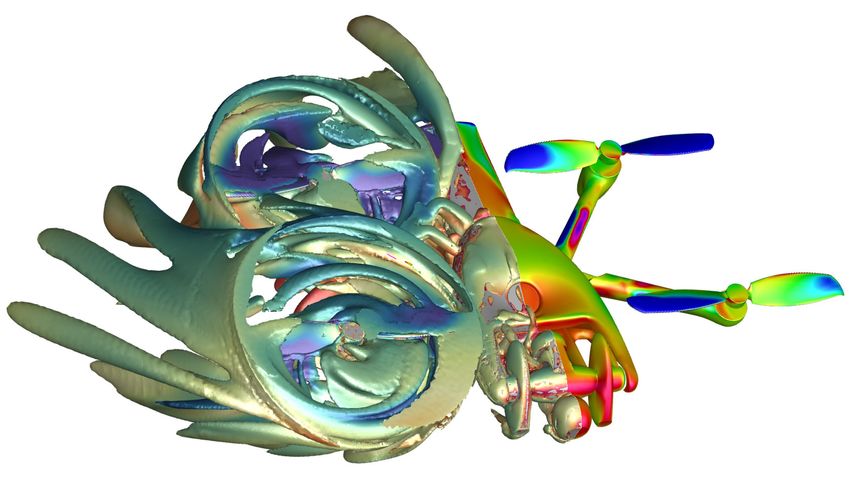
A naturalist remark
In the animal kingdom, there is no known
species that has optical sensors
distributed around its body.

No insect, bird, fish, or mammal has
developed a ‘visual perception system’ of
sensors, despite each species needing to
detect obstacles or predators in all
directions in order to survive.

Natural evolution has led to the most widespread and efficient solution. For example:

- mobile heads that can be oriented on 3 axes: left/right (yaw), up/down (pitch), and also to a lesser
extent with respect to the horizon (roll);

- this integrates a unique pair of sensors adapted to the animal's behavior, and installed on a vertical
plane of the face for tree-dwelling primates from which we descend, or directed more laterally for
equids for example;

- the pair of sensors are generally mobile on 2 axes: left/right (yaw axis) and up/down (pitch axis).

This visual perception is created of a pair of sensors (the eyes) mobile on 5 free axes (the
movements of the head and eyes in their orbits).

In biology, we also see this in the evolution of the optic nerve. For most species, the optic nerve is
the largest of its kind; it transmits large amounts of information across the body to its cerebral
support. It is also a very short nerve made up of a bundle of cerebral fibers. When we apply this to a
drone, the link (the “bus”) between the sensor and the processor requires an essential exchange of
information, which implies optimizing the length of the bus.

                                              Anatomically, the head of some species is often
                                              detached from the rest of the body. Some flying
                                              species (insects, birds, mammals) have their head
                                              located at the front of its frame, extending the view of
                                              the rest of the body - especially its wings. The
                                              placement of its head also allows its eyes to be
                                              positioned in such a way as to have an excellent field
                                              of view in all directions, and turning the head allows
                                              most flying species to see precisely behind them.

                                              It is from this system of visual perception and cerebral
                                              support emerges the cognitive functions - in this case
                                              the perceptive and conceptual functions.

                                              With this is in mind, Parrot has designed the ANAFI Ai
                                              obstacle avoidance system.

                                                                Henri Seydoux

                                                                Founder and CEO, Parrot Drones

ANAFI Ai – © Parrot 2021                                                                              5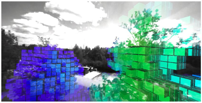
Flight performances
Key features
    -   32-minute flights
    -   Best-in-class input power/output power ratio (propellers: 66 % figure of merit)
    -   Designed for outdoor missions as well as indoor (warehouses, tunnels)
    -   Rotating twin sensor for obstacle avoidance
    -   IPX3: withstands rain and 45 km/h winds

A cool drone
By their design, ANAFI Ai and its Skycontroller 4 are a milestone for the UAV industry: the controller
does not require cumbersome cables anymore, and it enables the use of an iPad mini or all large
smartphones. It also features a HDMI output, which allows streaming videos from ANAFI Ai.

ANAFI Ai is Parrot’s new cool drone: it looks nice, it is intriguing, foldable, operational in 1 minute and
resistant to rain.

Aerodynamic performances

 Maximum speed                              17 m/s forward – 16 m/s backward and laterally

 Wind resistance                            12.7 m/s

 Flight time                                32 min

 Max Climbing Speed                         4 m/s

 Max Descent Speed                          3 m/s

 Max practical ceiling above sea level      5,000 m

 Range                                      22.5 km at 14 m/s without wind

 Max Angular Speed                          300°/s on pitch and roll axes & 200°/s on yaw axis

6                                                                                                     v1.4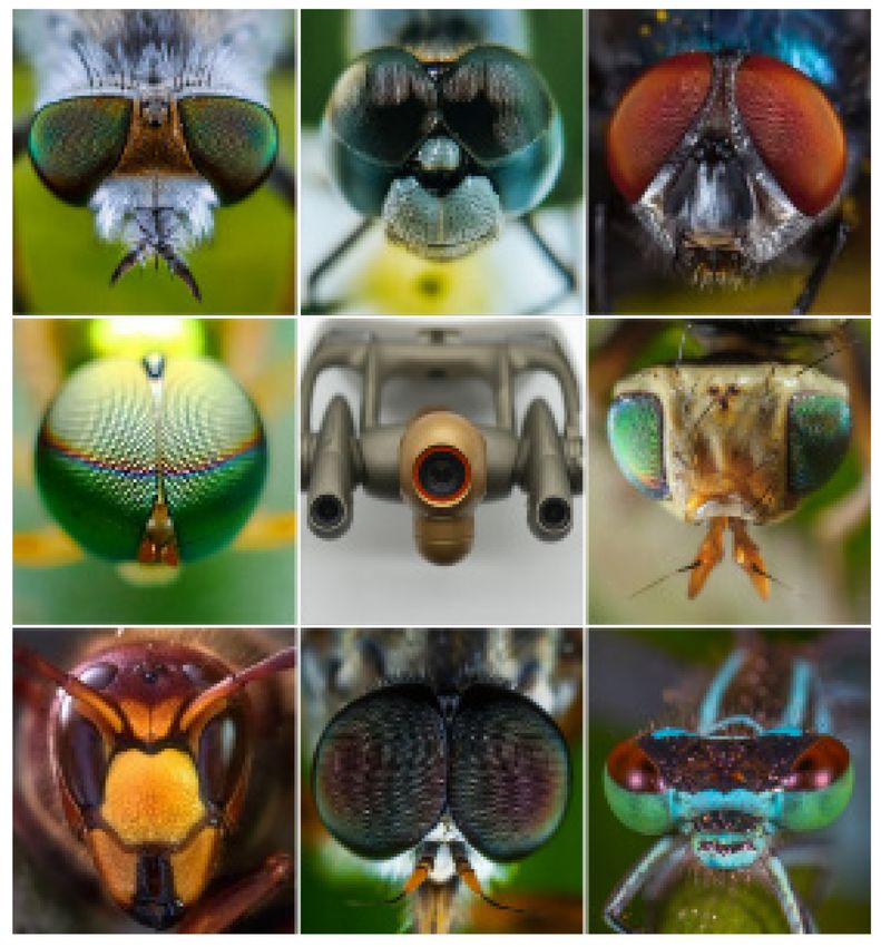
Actuators and aerodynamics

                                     CFD view of an ANAFI Ai propeller blades

Designed by biomimicry, the new bio-inspired propeller blades use a leading edge similar to the
shape of the fins of humpback whales.

This allows a better propulsive efficiency. For the same rotation speed, the thrust is increased. The
effect is comparable to an enlargement of the rotor diameter.

Propellers achieve a Figure of Merit of 66%. The Figure of Merit is used as a performance indicator
of a propeller design, it can be seen as an equivalent of the efficiency. Efficiency is defined by the
ratio between input power and output power, whereas on a drone propeller we use the figure of
merit (the ratio between the input power and an “ideal power”) which is a theoretical maximum value
of power provided by a propeller of a given size.

Acoustic noise is also reduced, especially on the tonal noise coming from the leading edge.
Therefore, ANAFI Ai is quieter [71.5 dBSPL (A) at 1 m] than the Skydio 2 [76.4 dBSP (A) at 1 m].

    •   Flight time of more than 32 minutes.
    •   Top speed of 17 m/s (61 km/h) in forward flight and 16 m/s (58 km/h) in lateral and backward
        flight, thanks to the optimized aerodynamic performance of the body and the ANAFI Ai
        powerplant.
    •   Wind resistance is 12.7 m/s (45 km/h).
    •   22.5 km range at 14 m/s without wind thanks to the high efficiency of the motor/propeller
        torque and the high autonomy of the battery.

Following is a list of aerodynamic simulations performed in the development phase.

    •   Parrot designs the conversion chain using digital multiphysics simulation tools. These tools
        and the Matlab numerical models developed in-house enable us to determine the drone's
        performance for a given size, mass and power consumption, right from the specification
        phase.
    •   The numerical models allow us to dimension the UAV according to the customer's needs.
    •   Modeling of the propulsion unit (CFD).
    •   Modeling of the drone body (CFD).

ANAFI Ai – © Parrot 2021                                                                            7
CFD views of ANAFI Ai arms

Test in development phase:

    •   Tests carried out on the bench of the propulsion unit (engine, propellers),
    •   Wind tunnel tests to determine aerodynamic performance (body, propellers),
    •   Production test:
           o All the sub-assemblies making up the UAV are checked on the production bench.
           o Every drone undergoes a flight test before it is packed: take-off, hovering, landing.

Sensors
To ensure its safe flight, ANAFI Ai is equipped with:

    -   2 IMU (an ICM-40609-D and an ICM42605)
    -   LIS2MDL magnetometer
    -   UBX-M8030 GPS
    -   TI OPT3101 time-of-flight (ToF)
    -   LPS22HB barometer
    -   vertical camera

The ToF is responsible for providing a ground distance measurement and consists of an infrared
transmitter-receiver measuring the drone-object distance according to the round-trip time of a light
emission between the object and the onboard sensor.

The ToF has the following advantages compared to the ultrasound:

    -   Smaller minimum measurable distance: 10 cm versus 40 cm for the ultrasound
    -   Higher maximum measurable distance: 9 m for a target with IR reflectivity of 80%, against
        5 m for ultrasound on concrete.
    -   No disturbance from other close-by drones

Several calibrations are applied to the ToF to ensure the reliability of its measures:

    -   Crosstalk correction on each individual drone (between diode and photodiode)
    -   Distance offset on each individual drone (based on a known distance)
    -   Temperature sensitivity (compensation by a distance offset dependent on the
        temperature)
    -   Ambient IR light sensitivity (compensation by an offset dependent on the light intensity)

8                                                                                               v1.4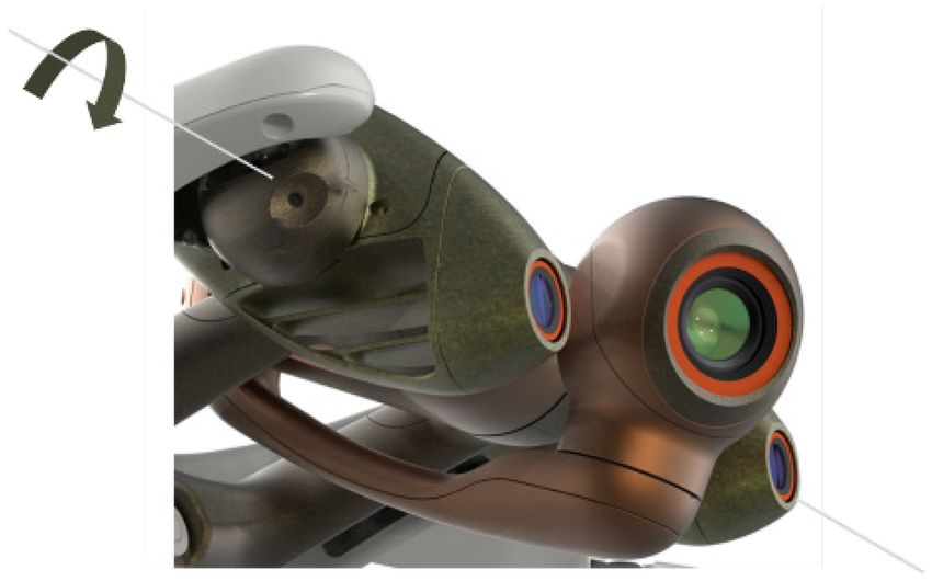
ANAFI Ai is also equipped with a multidirectional depth sensing system (stereo vision) described in
the “Autonomous Flight” section.

Sensors’ characteristics
Flight IMU: ICM-40609-D
    - 3 axes gyroscope
    - Range: ± 2000 °/s
    - Resolution: 16.4 LSB/°/s
    - Bias/accuracy: ± 0.05°/s (after thermal and dynamic calibration)
    - 3 axes accelerometer
    - Range: ± 16g,
    - Resolution: 2.048 LSB/mg
    - Bias/accuracy: ± 0.5 mg (X-Y) ± 1 mg (Z) (after thermal and dynamic calibration)
    - Temperature regulation: controlled heating system in relation to the ambient temperature,
         stabilized within: ± 0.15 ° C
    - Measurement frequency: 2 kHz

Magnetometer: LIS2MDL
   - Range: ± 49.152 G
   - Resolution: 1.5 mG
   - Bias/accuracy: ± 15 mG (after compensation, at maximum motor speed)
   - Measurement frequency: 100 Hz

Barometer: LPS22HB 1
   - Range: 260 to 1260 hPa
   - Resolution: 0.0002 hPa
   - Bias/accuracy: ± 0.1 hPa
   - Temperature regulation: controlled heating system in relation to the ambient temperature,
      stabilized within: ± 0.2 ° C
   - Frequency of measurement: 75 Hz
   - Measurement noise: 20 cm RMS

GNSS: UBX-M8030 1
  - Ceramic patch antenna of 25x25x4mm allowing a +2dB gain improvement compared to
      ANAFI 1
  - Sensitivity: cold start -148 dBm / tracking & navigation: -167 dBm
  - Time-To-First-Fix: 40 seconds
  - Bias/accuracy
         o Position: standard deviation 1.4 m
         o Speed: standard deviation 0.5 m/s

Vertical camera
   - Sensor format: 1/6 inch
   - Resolution: 640x480
   - Global shutter sensor
   - Black & white
   - FOV: horizontal viewing angle: 53.7° / vertical viewing angle: 41.5°
   - Focal length: 2.8 mm
   - Optical flow ground speed measures at 60 Hz
   - Point of interest calculation for accurate hovering at 15 Hz and accurate landing at 5 Hz

ANAFI Ai – © Parrot 2021                                                                         9
ToF: TI OPT3101
   - Range: 0-15 m
   - Resolution: 0.3 mm
   - Bias: ± 2 cm (after calibration)
   - Measuring frequency: 64 Hz

Vertical camera IMU: ICM-42605
   - Gyroscope 3 axes
   - Range: ± 2000 °/s
   - Resolution: 16.4 LSB/°/s
   - Bias/accuracy: ± 0.1 °/s (after dynamic calibration)
   - 3-axis accelerometer
   - Range: ± 16g
   - Resolution: 2.048 LSB/mg
   - Bias/accuracy: ± 2.0 mg (X-Y) ± 5.0 mg (Z) – after dynamic calibration
   - Measuring frequency: 1 kHz
   - Hardware synchronization with the vertical camera, accuracy: 1 µs

Autopilot
Key features
The ANAFI Ai flight controller offers an easy and intuitive piloting: no training is required to fly it. It
allows the automation of many flight modes (Flight Plan, Cameraman, Hand take-off, Smart RTH).

Sensor fusion algorithms combine the data from all sensors to estimate the attitude, altitude,
position and velocity of ANAFI Ai.

State estimation is essential for the proper functioning of drones. Quadrotors are by nature
unstable when the flight controller is in open loop; to pilot them easily, let alone to operate them
autonomously, it is necessary to stabilize them by closed loop control algorithms. These algorithms
compute and send to the motors the commands needed for ANAFI Ai to reach the desired
trajectories.

Estimation
ANAFI Ai estimates the states of the UAV from sensors measures via several data fusion algorithms
such as extended Kalman filters. The main estimated states are the following:

     -   Ground speed on x, y and z axes in drone frame, in [m/s]
     -   Attitude Euler angles (roll, pitch, yaw), in [rad]
     -   Accelerometer bias on x, y and z axes in drone frame in [m/s²]
     -   Gyroscope bias on x, y and z axes in drone frame in [rad/s]
     -   Magnetometer bias on x, y and z axes in drone frame in [mG]
     -   Pressure sensor bias, in [m]
     -   Position on x, y axes in NED frame, in [m]
     -   Altitude above take-off, in [m]
     -   Altitude above ground level, in [m]
     -   Wind on x, y axes in NED frame, in [m/s]
     -   Propulsion vector mechanical misalignment (roll, pitch)

10                                                                                                    v1.4
Control
Control algorithms determine the commands needed by the drone motors to reach the given
guidance references from the current estimated states. The ANAFI Ai control architecture includes:
- A gravity compensation algorithm, robust to mass variations
- an inner pitch/roll attitude loop
- an outer position loop
- an altitude loop
- a yaw attitude loop
All control loops use trajectory feedforward generators to ensure the desired trajectory dynamics
and disturbance rejection mechanisms.
A mixing algorithm combines the output commands from the different loops ensuring that given
motor speed saturation bounds are respected. Under conditions of saturated motors, the following
priority order is defined for commands application:
- Gravity compensation
- Roll
- Pitch
- Yaw
- Altitude variations
This means that in presence of strong disturbances which would make it impossible for the drone
to keep stability on all axes, control errors will be allowed on the different axes by respecting the
order described above.
In parallel, control will adjust the drone speed to get out of the saturated motor condition while
following at its best the guidance command.
Indoor flight
In the absence of GPS signal, ANAFI Ai relies mostly on the vertical camera measures for velocity
and position estimation.
Vertical camera measures are given by two main algorithms.
Optical flow for velocity estimation:
• Computes a translation in pixels between two successive images at a normalized ground
distance of 1 m
• This translation is multiplied by the ground distance in order to obtain a translation in meters.
• To obtain a velocity measure, the translation in meters is divided by the time elapsed
between the two images
• For the algorithm to perform correctly, the orientation between images must be corrected
when computing the pixels translation, which is made by using the vertical camera IMU
measures
• The algorithm runs at 60 Hz
Keypoint detection and matching for position estimation:
• Starts from a reference image that is taken when the drone starts a hovering with
appropriate light conditions
ANAFI Ai – © Parrot 2021 11• Then, at each new image, it looks for points which can also be found in the reference image
(matching)
• From these matches, it computes the camera displacement between both images, for
which attitude stabilization is also necessary
• The drone displacement between two images is computed from the camera displacement
and the ground distance
• The algorithm runs at 15 Hz
Velocity measures from optical flow are used by fusion data algorithms along with flight IMU and
ToF measures to produce a reliable velocity and ground distance estimation during hovering and
flight.
During hovering, position measures from keypoint detection and matching are also added to the
data fusion, thus helping ANAFI Ai maintain a precise fixed point: the drone remains stable in a
sphere of a 5 cm radius at 1 m altitude – against +/- 10 cm for the Mavic PRO (depending on the
spec). Measures from keypoint detection and matching are also used when ANAFI Ai rotates
around its yaw axis, or when it performs vertical movements (no longitudinal or lateral flight), thus
ensuring precise rotations and ascent/descent.
Vertical camera algorithms are still able to run in low light conditions thanks to the fact ANAFI Ai is
equipped with a pair of LED lights, located next to the vertical camera. These allow the drone to
keep stability, especially when flying indoors or in a GPS-denied environment, below 5 m over the
ground. The LED lights power adapts automatically, depending on the algorithms’ needs.
Autonomous flight
Key features
• Rotating, wide field of view perception system
• Surrounding environment depth extraction from stereo matching and depth from motion
• Occupancy grid representation of the environment
• Autonomous obstacle detection and avoidance at speed up to 8m/s (29 km/h - 18mph)
This chapter details the sensors, hardware and algorithms used by ANAFI Ai to provide
autonomous flight capabilities.
It is organized as follows:
• in-depth description of the perception system of ANAFI Ai
• perception algorithms used to reconstruct the 3D environment surrounding the aircraft
• replanning and obstacle avoidance
Perception system strategy
3D environment perception is a key capability to achieve autonomous flight, especially in
obstructed environments. It is a condition for guaranteeing obstacle detection and avoidance,
which reduces the supervision load of the drone operator, increases the mission success rate and
ensures the safety of the aircraft.
An efficient perception solution is required to unlock the full potential of a flying camera, able to
translate and rotate freely in all directions without constraint. In particular, a perception system must
allow capturing information on the surrounding environment, in directions that are consistent with
the translational flight motion – whatever the orientation of the camera.
12 v1.4ANAFI Ai relies on a unique technical solution based on two mechanical gimbals to decouple the
orientation of the main camera and the perception system:
• the main camera is mounted on a pitch-roll-yaw 3-axis gimbal making its 3D orientation
independent from that of the drone
• the perception system is mounted on a single axis pitch gimbal – coupled to the drone’s yaw
movement, it can be oriented in any direction
The pitch axes of the two gimbals are colinear and merged to achieve an ultra-compact design.
ANAFI Ai's dual gimbal for perception and imaging
With this solution, it is possible to point the main camera and the perception system in two different
directions. This design avoids the use of expensive cameras on the sides, top, bottom and back of
the drone, while still providing a large accessible field of view to the perception system.
This section is organized as follows:
• details on the sensors used for the perception system
• specifications of both the gimbal of the main camera and the one of the perception system
• strategies for orienting the perception system to exploit the potential of the dual gimbals
design
ANAFI Ai – © Parrot 2021 13Sensors
The perception system relies on a pair of identical cameras, sharing the same pitch axis.
Single axis pitch gimbal of ANAFI Ai's perception system
The specifications of the sensors are the following:
• Model: Onsemi AR0144CSSM28SUD20
• Color: monochrome
• Resolution: 1280 x 800 pixels
• Frame rate: 30 fps
• Global shutter
• Full horizontal field of view: 118.5° (110° used for perception)
• Full vertical field of view: 82.5° (62° used for perception)
• Focal length: 1.55 mm (0.061”)
• Aperture: f/2.7
The specifications of the stereo pair are the following:
• Shared pitch axis
• Baseline/distance: 70 mm (2.44”)
• Synchronous acquisition at 30 fps
14 v1.4Dual Gimbal
The gimbal of the main camera is a pitch-roll-yaw 3-axis gimbal with the following specifications:
• pitch end stops: -116°/+176°
• roll end stops: +/- 36°
• yaw end stops: +/- 48°
The gimbal of the perception system is a single axis pitch gimbal with the following specifications:
• pitch end stops: -107°/+204°
• time of travel from one end stop to the other: 300 ms
The perception system benefits 311° of travel (296° unmasked by the drone body), which allows
backward perception.
Instantaneous vertical field of view and end stops of ANAFI Ai's perception system
The system has been designed so that:
• the propeller blades cannot enter the field of view of the main camera
• the main camera does not mask the field of view of the perception system
• both the main camera and the perception system can fully tilt backward to protect the
lenses, during storage or in case of in-flight emergency
ANAFI Ai – © Parrot 2021 15Horizontal field of view of ANAFI Ai's perception system
When tilted backward, the perception system rotates high up, offering a clear view.
ANAFI Ai's perception in fully tilted position for backward flight
16 v1.4Quality control: the gimbals have been bench tested for 125 hours straight with no defect or wear
noted. Each gimbal is tested at every stage of production, including:
• control of the motors and motors assembly
• calibration of the stereoscopic cameras poses
• control of hall sensors amplitude, bias and noise
The quality control data can be provided under customer request.
Perception system orientation strategies
For autonomous flight modes, a “crab flight mode” has been designed to exploit the entire field of
view accessible to the perception system through the dual gimbal design:
• the 3-axis gimbal main camera is always pointed in the user defined direction
• by rotating the drone around its yaw axis and by pitching single axis gimbal of the
perception system, the direction of translational flight motion is kept within the field of view
of the perception system
ANAFI Ai performing crab flight, orienting its perception system in a useful direction while pointing its main camera in the
specified recording direction
A simpler strategy is applied for take-off and landing phases:
• At take-off, the perception system is oriented upward
• For the landing, the perception system is oriented downward
ANAFI Ai – © Parrot 2021 17During take-off and landing phases, ANAFI Ai's perception system is oriented vertically
Environment reconstruction
The reconstruction of the surrounding 3D environment for autonomous flight is performed in two
steps:
• extraction of depth information from the perception, as depth maps
• depth maps data fusion into a 3D occupancy grid
Two methods are used to generate depth maps from the perception sensors:
• depth from stereo matching
• depth from motion
Depth from stereo matching
The main method used for depth information extraction relies on the parallax between the two
stereo cameras of the perception system. By photographing the environment in the same direction
but from two different positions, objects in the field of view of the perception system appear at
different positions in the pictures produced by the two cameras. The closer the object, the closer
this difference in position.
The strategy thus consists in identifying points in the pictures produced by the left and right stereo
cameras corresponding to a same feature in the field of view of the perception system and
measuring the position difference of these points in the two pictures. This difference is called the
disparity and is measured in count of pixels.
18 v1.4Illustration of the stereo vision principle – the red 3D spot appears in different positions on the left and right images
The disparity can then be linked to the depth of each of these points using the following relation:
depth = focal * baseline / disparity
where the depth and the baseline are expressed in the same unit, and the focal length and disparity
are expressed in pixel count.
The result of the computation takes the form of a 176 x 90 pixels depth map, for which the value of
each pixel corresponds to a depth, in meters. The depth map is updated at 30 Hz.
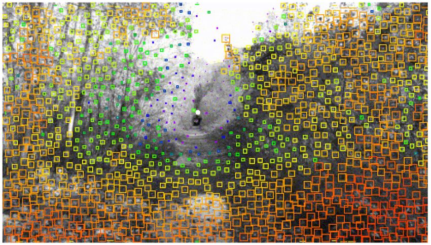
Example of image captured by the right camera of ANAFI Ai's perception system (left) and the corresponding depth
obtained by stereo matching (right). The color map goes from red (closer) to purple (far) – white meaning “out of reach”
An immediate result is that the depth measured through this method is discretized, as the disparity
can only take discrete values (count of pixels). A 3D point sufficiently far from the perception system
that would generate a theoretical disparity smaller than one pixel will thus be considered at infinity
as the corresponding actual, discrete, disparity will be 0. The precision of the stereo matching
method hence decreases with the distance, though methods exist to reduce this phenomenon by
achieving subpixel discretization.
ANAFI Ai – © Parrot 2021 19Discretized depth measured by “stereo matching” vs “true depth” In addition, the disparity diverges as depth get closer to zero. Since the number of pixels in the images is limited, so is the value of the disparity. As a consequence, there is a minimum depth under which the perception system is blind. The value of this minimum depth is 36 cm (14.2 inches) for ANAFI Ai. About calibration: each pair of stereo cameras is factory-calibrated to precisely measure the slight misalignments that may exist between the two cameras and to compensate for it in the onboard computation of the depth. The user can also recalibrate the stereo camera pair with the test pattern provided in the packaging. In particular, to some extent, the drone is capable to detect potential calibration errors that may occur over its lifetime. In that case, the drone software will try to adjust and compensate for it, or if it fails to do so, a notification will appear to request a recalibration. Depth from motion The motion of the aircraft can also be exploited to collect images of the environment from different point of views, and thus reconstruct depth information. This method is called depth from motion, or monocular perception, since a single moving camera suffices to gather depth information. The principle is similar to the stereo vision, but rather than comparing images of the environment acquired by distinct observers at same time, the perception compares images of the environment from a same observer at different times. Should the drone be moving, the images from this unique observer will be acquired from different points of view. Knowing the pose at which each frame was taken, points corresponding to a same feature in the different images can be triangulated and put back in 3D. This results in a 3D point cloud, containing up to 500 points for ANAFI Ai, generated at 10Hz. 20 v1.4
Example of point cloud produced through depth from motion – the color map goes from red (closer) to purple (far)

The depth from motion algorithm in ANAFI Ai usually generates less information (sparse point
cloud) than the stereo matching algorithm and requires the drone to be moving to gather
information. Furthermore, this algorithm fails to extract information in the exact direction of motion
(at least for straight translations) since in this direction, objects appear almost motionless in the
images (focus of expansion).

However, it has a better range of detection (theoretically infinite range) that the stereo matching
method.

Occupancy grid

The depth information from the stereo and monocular perception algorithms is integrated into an
occupancy grid. This grid discretizes the 3D surrounding environment into 3D cubes, called voxels.
To each voxel is attributed a probability to be occupied by an obstacle or, on the contrary, to be free
of obstacle.

A raycasting algorithm is used to integrate the depth information into the occupancy grid. For each
pixel of the depth map generated by the depth from stereo matching, converted into a 3D point, and
for each point of the point cloud from the depth from motion:

    •    A ray is cast in the occupancy grid, from the position of the perception system, to the
         position of the 3D point.
    •    The probability of occupation of the voxel containing the 3D point is increased
    •    The probability of occupation of all the voxels crossed by the ray -except the one containing
         the 3D point- is decreased

ANAFI Ai – © Parrot 2021                                                                                           21
Raycasting principle – on the right, the depth map produced by the stereo matching, on the left, a 2D slice of the
occupancy grid. For each pixel of the depth map, a ray is cast from the position of the perception system to the 3D point
given by the direction corresponding to this pixel in the perception system's field of view and its associated depth. Each
voxel crossed by the ray has its probability of occupation decreased while it is increased in the voxel in which the ray
ends.
The grid thus acts both as a temporal filter of the depth information, absorbing any potential noise
in depth measurements and as a memory of the previous acquisitions, making it possible to
navigate in complex environments, even without a continuous 360° field of view of the perception
system.
Example of occupancy grid. The voxels with a high confidence of occupation are superimposed to the view of the right
stereo camera, with a color going from red (close) to purple (far).
The occupancy grid constitutes the base for the motion planning algorithms used by ANAFI Ai for
autonomous flight and obstacle avoidance.
Obstacle avoidance
With the knowledge of the 3D environment surrounding the aircraft stored in the occupancy grid, it
is possible to provide obstacle avoidance capabilities to ANAFI Ai. This offers considerable
additional safety to autonomous missions but is also useful for manual flight, especially if the line of
sight between the pilot and the aircraft is degraded.
22 v1.4Every 30 ms, ANAFI Ai predicts what the nominal trajectory to follow will be over a short time
horizon in the future. This prediction is deduced from the references sent by the user, whether it be
piloting commands from the hand controller, waypoints to join for flight plan or an input trajectory.
Then, using a simulated internal drone model, a replanning algorithm computes the smallest
possible corrections to this predicted nominal trajectory that make it both collision free and feasible
by the drone.
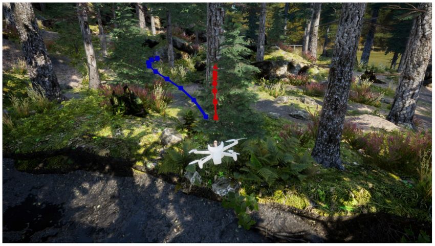
Example of corrected trajectory computed by the obstacle avoidance algorithm in response to a reference trajectory
hitting a tree
ANAFI Ai's obstacle avoidance has been designed to handle speeds up to:
• horizontal: 8 m/s (29 km/h - 18 mph)
• ascending: 4 m/s (14 km/h - 8 mph)
• descending: 3m/s (11 km/h - 7 mph)
Avoidance performances are limited in rainy or strong wind conditions, low light or disturbed
satellite navigation environment. Also, it should be ensured that the lenses of the perception system
are clean before flying.
Flight missions
Key features
Air SDK (see SDK section) allows developers to access every drone sensor, camera, connectivity
interface and autonomous feature. They can therefore customize the drone behavior to create
Flight missions. Every Flight mission contains a set of basic behaviors or modes:
- Ground: behaviors while motors are stopped, such as sensors calibrations
- Take-off: various take-off strategies
- Hovering: holding a fixed point
- Flying: manual and autonomous flight functions
- Landing: various landing strategies
- Critical: when a critical condition is detected
ANAFI Ai – © Parrot 2021 23The missions developed internally by Parrot and available in FreeFlight 7 are described in the FreeFlight 7 section. The main one is the Default mission. Custom Flight missions can write new behaviors or reuse them from the Default mission. Default Mission Take-off We have developed two behaviors, a normal take-off mode and a hand take-off mode. Normal take-off The drone stabilizes at 1m from the ground while holding a fixed point thanks to data fusion from different sensors, even in strong wind conditions (45 km/h). The user can give the drone piloting commands on pitch, roll and yaw axes during normal take-off. Hand take-off The drone starts the motors at minimum rotation speed before being launched by the user. Once freefall is detected, control algorithms are activated to stabilize the drone at the launch altitude. Landing Normal landing The drone reduces its vertical speed progressively until reaching the ground and stop the motors. The user can give the drone piloting commands both on pitch, roll and yaw axes during normal landing. However, an upward piloting command on vertical axis will abort the procedure, making the drone hold a fixed point. Critical landing Whatever the altitude of the drone, when the amount of energy remaining in the battery is close to the energy needed to land (calculated according to the altitude and wind strength), the critical landing procedure is triggered. The user can give the drone piloting commands on pitch, roll and yaw axes, but it will not be possible to abort the procedure. Hand landing When the drone is less than 3.5 m from the ground and hovering, the perception system automatically recognizes the presence of a hand. When a hand is detected, activating the Take- Off/Landing button triggers the hand landing process: ANAFI Ai moves horizontally directly over the hand and then descends on it. Algorithms based on sensors data have been specially adjusted to stop the motors as soon as possible after the contact of the drone with the hand. The hand perception module is based on a convolutional neural network "hardware" of the processor used on the drone trained with a database of more than 3000 hands seen from a drone. In addition to the neural network, a verification is performed with the depth map from the stereo camera, to validate that the detected object has the characteristics of a hand. 24 v1.4
Controlled flight
Piloting commands
Using the Skycontroller 4 or the virtual joysticks of FreeFlight 7, the user can directly send the
following inputs to the drone in manual flying mode:
• pitch angle (max 30°)
• roll angle (max 30°)
• vertical velocity (max 4m/s ascending, max 3m/s descending)
• yaw rate (rotation velocity, max 200°/s)
The maximum reachable horizontal speeds are:
• forward: 17m/s (61 km/h - 38 mph)
• backward: 16m/s (57 km/h - 36 mph)
• lateral: 16m/s (57 km/h - 36 mph)
In absence of pitch or roll inputs, the drone automatically cancels its horizontal motion.
It is possible to adjust the configuration of the joysticks through the settings of FreeFlight 7.
In this mode, the yaw of the main camera is locked aligned with the yaw of the drone, but its pitch
and zoom factor can be freely controlled by the user.
Obstacle avoidance
Obstacle avoidance algorithms can be activated in this mode and allows to reach:
• pitch angle (max 15°)
• roll angle (max 15°)
• vertical velocity (max 4m/s ascending, max 3m/s descending)
• yaw rate (rotation velocity, max 200°/s)
This allows speeds up to 8 m/s (28 km/h - 18 mph) in horizontal flight with obstacle avoidance
activated.
Note that even without obstacle avoidance, a safety prevents the drone to get closer than 35 cm
(14 inches) from the ground. This distance is increased to about 1 meter (3 ft) with obstacle
avoidance.
Geocage
A geocaging feature is available in this flight mode. When activated, this restricts the drone motion
in a virtual 3D cylinder centered of the take-off position. The radius and height of the cylinder can
be specified through FreeFlight 7 settings menu.
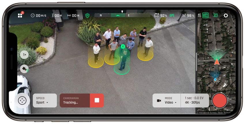
Cameraman
Target proposals are displayed on the screen. The user selects the target on the screen according
to 2 possibilities:
• the user selects a target among those proposed
• the user draws a rectangle to define a target
ANAFI Ai – © Parrot 2021 25Automatic target proposal / target selection Once the target is selected, the front camera automatically adjusts its attitude in order to keep it framed by means of visual tracking. The user can give the drone pitch, roll and vertical piloting commands to make it move around the target (the drone yaw angle is locked aligned with the front camera yaw). The visual tracking consists in merging: - A motion model of the target's position based on the drone's position - A visual tracking algorithm (optical flow, SVM-based online learning, scale change estimator) - A visual detection neural network The SVM algorithm initiates the tracking with a single image and continues to learn the target over time. The algorithm is able to track changes in the silhouette of the target, e.g. the algorithm tracks changes in direction of a moving vehicle (side view followed by rear view). 26 v1.4
The convolutional neural network identifies objects in the scene and recognizes them regardless of
their silhouette. This network is optimized on a base of Parrot images from our drones for a high
level of reliability.

The network is able to detect different classes of objects such as: people, cars, bikes, motorcycles,
boats, animals (cow, dog and cat), etc. These are the objects of these classes that are proposed to
the users to select a target.

POI
From the map, this flight mode allows to give the drone a point of interest by a simple designation
on the screen. The GPS coordinates of the selected point are transmitted to the drone and the front
camera automatically adjusts its attitude to keep it framed. The user can give the drone pitch, roll
and vertical piloting commands to make it move around the POI (the drone yaw angle is locked in
alignment with the front camera yaw).

Autonomous flight
Flight Plan
The flight plan mission allows the user to have the aircraft autonomously join a sequence of
viewpoints at specified speeds, while respecting specified camera orientation behaviors.

The mission can be prepared in off-line mode on the control screen by setting the waypoints along
with their altitude (above take off), the associated camera orientation and the speeds to join them.
Parrot has simplified the ergonomics of mission preparation, an operation that is generally complex
for the user. The flight plan can be edited, modified and replayed as many times as necessary.

Flight planning is possible without a radio connection to the remote control, but it requires the drone
to have access to a satellite navigation system.

                              Screen capture of FreeFlight 7 Flight Plan editor

Obstacle avoidance algorithms can be activated in this mode.

Available view modes include:

    •   Constant camera angle
    •   Progressive camera angle

ANAFI Ai – © Parrot 2021                                                                            27
• Point of interest
The maximum achievable speeds are:
• horizontal - without obstacle avoidance: 12 m/s (43 km/h - 27 mph)
• horizontal - with obstacle avoidance: 8 m/s (29 km/h - 18 mph)
• ascending: 4 m/s (14 km/h - 8 mph)
• descending: 3m/s (11 km/h - 7 mph)
In case of failure to join a waypoint (inaccessible waypoint for instance), the drone will automatically
join the next one after a short period of time.
The flight plan can be paused and directly restart to the currently join waypoint.
Touch & fly
From the map, this flight mode allows to give a destination to the drone by a simple designation on
the screen.
The GPS coordinates of the selected point are transmitted to the drone.
Return Home (RTH)
Accurate
The vertical camera takes a reference image at the end of take-off. When the drone lands or begins
the descent towards the take-off area in RTH, the algorithm takes new images in order to determine
the displacement relative to the reference image. This displacement is used as a guidance
reference for the drone.
Smart
The drone calculates the amount of energy needed to return to the home coordinates, depending
on the distance and wind strength, and compares it to the energy remaining in the battery. When
both energies are close enough, a critical RTH is triggered. This procedure can be cancelled by the
user.
Obstacle avoidance is available in this mode (see Autonomous Flight - Flight Plan section for flight
limits).
28 v1.4Vehicle Mission
FreeFlight 7 Vehicle Mission selection
The objective of this mission available on FreeFlight 7 is to autonomously fly in a vehicle-relative
frame (car, truck, boat...) with high precision. It also allows to take off and land on a moving vehicle.
This mission implements new ground, take-off, hovering, flying, landing and critical modes to fly
relative to the vehicle. The drone front camera is not necessarily oriented towards the vehicle, it can
be guided by the user. The controller and the phone must remain in the vehicle.
In this mission the drone is enriched with specific computer vision algorithms that provide the
vehicle position and velocity when it is above and in the field of view of the drone cameras. The
position and velocity measures from the different computer vision algorithms are fused with the
information from the controller's GPS and barometer to accurately estimate the vehicle trajectory
and then use it as a reference for the drone.
At any time, the user can over-pilot and/or take control of the drone if no information is given by the
drone cameras.
A custom flight mode allows the drone to return autonomously above the vehicle at the user’s
demand or when the amount of energy needed to reach the vehicle gets close to the energy
remaining in the battery. The vehicle position is then predicted according to its speed and direction
to optimize the distance and the path to travel.
ANAFI Ai – © Parrot 2021 29Hybrid stabilization
The ANAFI Ai camera has the most accurate stabilization of the micro-UAV market.
It combines a double stabilization:
• 3-axis with the mechanical gimbal
• 3 axis with electronic stabilization (EIS)
The mechanical stabilization stabilizes the camera's aiming axis regardless of the drone's flight
attitude. The electronic stabilization of the image allows to correct the effect of the micro-vibrations
for the frequencies beyond 100 Hz which cannot be managed by a mechanical actuator.
ain camera g imbal
The mechanical stabilization allows the stabilization and orientation of the camera's horizontal
viewing axis on all 3 axis.
The 3 axes of rotation of the main camera’s gimbal
Key features
• 3 axes of mechanical stabilization for the main camera
• 292° vertical displacement, field of view from -116° to +176°
30 v1.4Performances
Gimbal performances
ANAFI Ai Skydio 2 MAVIC 2 Air
Angular stabilization ±1° No data No data
accuracy
End stops Pitch: -116/+176° Pitch: ±124° Pitch: -135°/+45°
Roll: ±36° Roll: ± 120° Roll: ±45°
Yaw: ±48° Yaw: ± 12.5° Yaw: ±100°
Piloting range ±90° (pitch axis) -110°/+45° -90° /24°
Maximal rotation speed ±180°/s (pitch axis) No data 100°/s
Protection Front camera No data None
crashproof self-
protection
The EIS algorithm corrects the effects of wobble and the distortion of the wide-angle lens, and it
digitally stabilizes the image along the 3 axes (roll, pitch and yaw).
The method consists of applying a geometric transformation of the image. The geometric
transformation is associated to a timestamp and a precise position thanks to the IMU.
A geometrical transformation is applied to each image according to the distortion of the optics, the
wobble and the movements of the camera module measured.
292° tilt range
The camera can tilt vertically by -116/+176° around the pitch axis, providing observation above and
below the drone. This is a unique capability in the micro-UAV market.
ANAFI Ai – © Parrot 2021 314G Connectivity
Key features
• Always connected, worldwide continuous connection to the Internet
• Seamless Wi-Fi to 4G switch: flies Beyond Visual Line Of Sight
• Worldwide LTE compatibility
• Real time streaming with 12 Mbps video bitrate / Low latency 1080p streaming
• In-flight cloud file transfer
4G
ANAFI Ai integrates a Fibocom L860-GL 4G LTE module (in addition to the Wi-Fi radio) allowing to
transmit a video in 1080p with a very low latency (300 ms) without range limit and everywhere in
the world.
Compatibility
The ANAFI Ai 4G module supports more than 28 frequency bands, covering more than 98% of the
frequencies deployed around the world.
LTE FDD: 1, 2, 3, 4, 5, 7, 8, 12, 13, 14, 17, 18, 19, 20, 21, 25, 26, 28, 29, 30, 32, 66 bands
LTE TDD: B38/39/40/41/42 bands
DL 4x4 MIMO: 1, 2, 3, 4, 7, 30, 40, 41NB, 66 bands
UMTS: 1, 2, 4, 5, 8 bands
LAA: band 46
Automatic network switch
The quality and capacity of the 4G and Wi-Fi networks are measured every 100 ms to adapt the
streaming to the network conditions. Combined with the routing algorithms, the connection
between the drone and its controller is maintained even when the Wi-Fi is strongly disrupted. Thus,
when the effective throughput (goodput) of Wi-Fi is lower than 1.5 MBps, the system automatically
switches to 4G.
32 v1.4To limit mobile data consumption when the pilot is within range of the drone's Wi-Fi network, the 4G to Wi-Fi transition is also automatically performed, without video stream cut. Implemented video stream optimization algorithms: Congestion control 4G The congestion control algorithm allows to: • Measure packet loss over the entire network loop • Measure the latency (Round Trip Time) • Adapt the throughput according to these two parameters The final objective of the algorithm is to maximize the available throughput while maintaining the lowest possible latency. This algorithm is implemented on each of the interfaces available on the drone, each one having its own parameters optimized according to the network. Thanks to the information provided by this algorithm, the link supervisor decides on the routing and the active interface. Remote control drone connection in 4G ANAFI Ai connects to the 4G remote control in less than 30 seconds when the drone is not in Wi-Fi range, and in less than 15 seconds when the drone is in Wi-Fi range. - Discovery and initiation of the connection based on the VOIP SIP protocol - Use of a relay server to establish the connection on secured networks Video stream performances - Latency: 300 ms - Security: Video and controls secured by SRTP/DTLS in accordance to webRTC - Antennas: 28 LTE bands between 700 MHz and 2.6 GHz ANAFI Ai – © Parrot 2021 33
You can also read


