SWITCHMATE - 2ND EDITION - SCIENTIFIC DEVICES AUSTRALIA
←
→
Page content transcription
If your browser does not render page correctly, please read the page content below
SwitchMate
A practical guide to Switching for Automated Test Systems

                                                            2nd Edition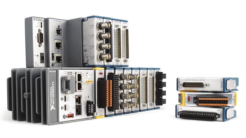
SwitchMate
This book provides a description of switching via electronic relays.

It provides an overview for those new to switching and a useful source
of reference material for the more experienced.

This is a living document that Pickering Interfaces will continue to develop
 in support of switching standards and their future evolution. We welcome
any feedback from users on subjects they would like to be included in future
issues.

© COPYRIGHT (2019) PICKERING INTERFACES. ALL RIGHTS RESERVED.
No part of this publication may be reproduced, transmitted, transcribed, translated or stored
    in any form, or by any means without the written permission of Pickering Interfaces.
  Technical details contained within this publication are subject to change without notice.

                                    pickeringtest.com
The following are terms are registered trademarks of the respective companies and/or organizations:
LabVIEW, LabWindows/CVI: National Instruments Corporation
PXI: PXI Systems Alliance
LXI: LXI Consortium
PICMG-PCI: Industrial Computer Manufacturers Group, Inc.
Illustrations with company names in parentheses are the manufacturer of the product displayed.

                                                                                                      Page i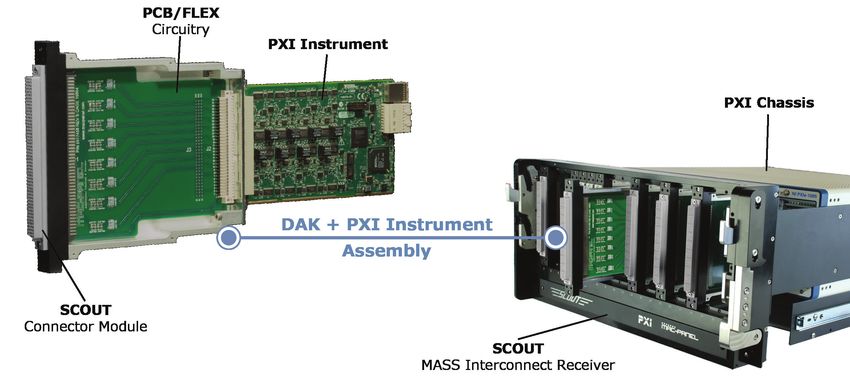
CONTENTS

               SECTION 1 - INTRODUCTION
               SECTION 2 - WHY IS SWITCHING IMPORTANT?
               SECTION 3 - SWITCHING BASICS
               SECTION 4 - PLATFORMS
               SECTION 5 - LEGACY SYSTEMS
               SECTION 6 - SWITCHING CONFIGURATIONS
               SECTION 7 - CABLES AND CONNECTORS
               SECTION 8 - RF SWITCHING
               SECTION 9 - FAULT INSERTION SWITCHING
               SECTION 10 - USEFUL INFORMATION

Page ii
1 - INTRODUCTION

                                            SECTION 1

                                         INTRODUCTION

The goal of this document – SwitchMate – is simple: to give your test engineers the knowledge to
make proper selections and to know what questions to ask of your switching vendors. One book will
not answer all your questions, but it is a good place to start.
With a 50-year history of manufacturing instrument-grade Reed Relays and high performance
Switching Systems, Pickering Interfaces has a significant body of experience in signal switching
for test. Sharing this expertise, then, is the driver behind SwitchMate, a document designed to take
you through all of the tough choices you need to make when selecting and integrating a switching
system. From relay types, to system configurations, cables and connectors to platform types, and
URLs to help you research your selections, at Pickering Interfaces we hope SwitchMate will prove to
be an important asset in your test engineering library.
It is important to note that SwitchMate is not about Pickering Interfaces products. True, there are
photos of Pickering Interfaces products used as examples throughout SwitchMate, however our
goals are to present switching from all possible perspectives – platforms, configurations, cabling and
so on. The questions raised apply to any switching vendor, including companies that build their own
switching systems.
Pickering Interfaces would like to thank its colleagues at Pickering Electronics and Pickering Connect
for their valuable expertise and input. Also deserving of recognition are two partners, MAC Panel and
Virginia Panel Corporation, who helped immensely with the section on Mass Interconnect systems.
I also want to thank National Instruments for allowing me to add their CompactRIO® switching and
United Electronic Industries for permission to refer to their Cube™ and RACKtangle™ switching in
Section 4. In addition, RfCafe.com and Wikipedia are to be commended for excellent information
on coaxial cables. And finally, thanks to Forrwords Marketing Communications for ensuring that my
writing was clear and consistent.
A word of caution before you move on. Too often customers have indicated they feel switching is the
LAST portion of their test integration strategy. Switching is so simple, maybe boring… how can you
go wrong there? At Pickering Interfaces, experience has shown there can be troubles down the road
if switching is not considered in the early phases of test system design. Switching selection affects
the accuracy, repeatability, speed, and even the safety of your test system.
Finally, if you feel the recommendations in SwitchMate are incorrect or incomplete, please contact
us. Even after 50 years, we still have things to learn!
          Bob Stasonis – Technical Product Specialist (bob.stasonis @pickeringtest.com)

                                                                                                   1.1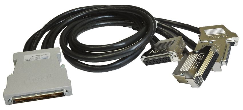
2 - WHY IS SWITCHING IMPORTANT?

                                               SECTION 2

                               Why is Switching Important?

Introduction........................................................................................... 2.3

                                                                                                              2.1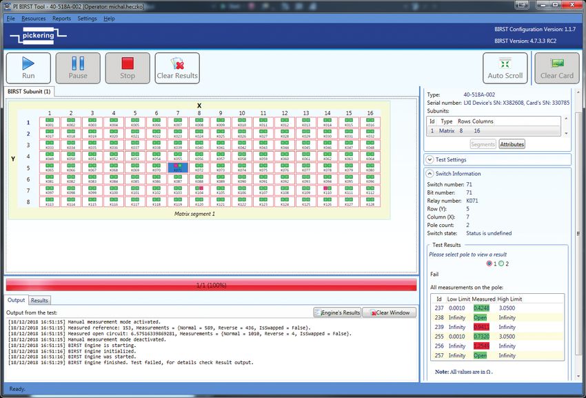
2 - WHY IS SWITCHING IMPORTANT?

2.2

2 - WHY IS SWITCHING IMPORTANT?
Signal switching can, in many instances, be the “heart” of your test system. By that we mean that
signal switching connects instruments to the DUT (Device Under Test) and vice versa. Without that
flow of “blood” (information) between the test system and the DUT, there is no operating test system.
Quality problems cannot be diagnosed or perhaps will be incorrectly diagnosed. Poor switching
choices affect accuracy, repeatability, and even system up time. The fact that you are reading this
book implies you recognize the importance and want to learn more.
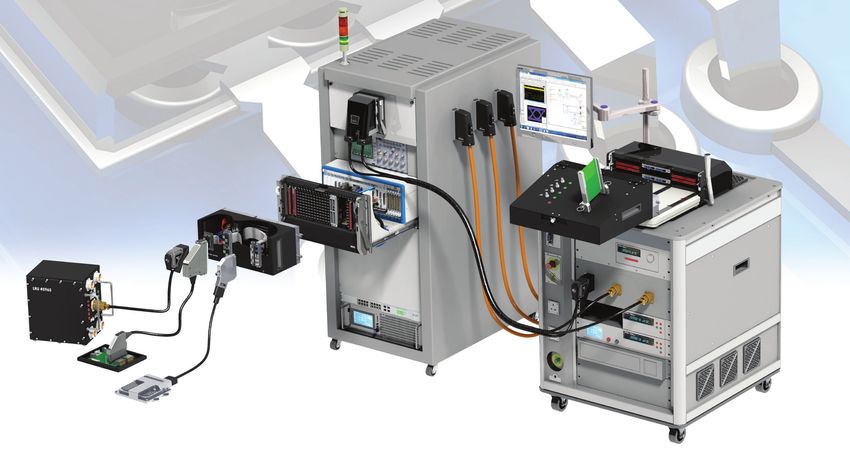
Fig. 2.1 - Switching Hardware
In developing a better understanding of Signal Switching in Test, you need to know the types of
switching configurations available, how relay types selected can influence your test strategy, and
how the connectivity of the instruments and switching can be crucial. Once you have this knowledge
there are questions to ask of your selected switching vendor.
Finally, it is important to understand that one test platform does not fit all switching applications. The
various platforms to be discussed – PXI, LXI, and USB – all have specific advantages in various
applications.
To begin, it is important to understand why switching is necessary or, as it is also called, “Signal
Management.” It is probably not a stretch to suggest most of you know that testing is a cost center:
No additional benefit to increase the bottom line, or so many managers believe. But without testing,
quality may suffer, especially in early production runs. Today’s zero defect culture demands constant
vigilance in ensuring production quality – detecting and quarantining failures requires strong testing
culture, and it’s not only for aerospace – driving FIT (Failures In Test) rates to zero is just today’s
6 Sigma culture. Nothing hurts a company’s reputation more than a purchased product out of the box
that does not work. And if this product is safety related – say, anti-lock brakes – failure can be very
expensive! So clearly, planning and implementing a comprehensive test program strategy is of the
utmost importance. And in virtually all applications, your test system will require switching. So, let’s
delve into the hows and whys of Signal Switching.
2.3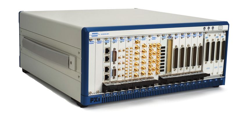
2 - WHY IS SWITCHING IMPORTANT?

                             Fig. 2.2 - Manual Test Measurement
There are multiple reasons why you need to implement Signal Switching. The first and most obvious
reason is to share resources. Generally speaking, you do not make just one voltage measurement
or one waveform measurement in a test program. There are multiple measurements to be made
to ensure that a DUT is fully operational. And if you do not share one Digital Multimeter (DMM) or
digitizer using switching, the solution is to have an operator move a probe around the DUT. This can
be time consuming and error prone. Of course, you can have multiple DMMs in your test system, but
that can be costly and make the test system overly large.
If you are testing multiple DUTs, switching is even more important. We have seen complex switching
systems used to create an asynchronous test strategy, where the operator can replace a DUT in the
test fixture while other DUTs are still being tested. This allows the test system to be more efficient,
lowering the cost of test and potentially reducing the number of test systems needed.
For portable applications, switching can shrink a test system footprint by more tightly integrating
instruments. The sharing mentioned earlier allows the test system to potentially have fewer
instruments.
When dealing with HALT/HASS Applications – HALT is Highly Accelerated Life Testing and HASS is
Highly Accelerated Stress Screening – switching is usually required to access multiple DUTs in an
environmental chamber. Because these tests can take weeks and months, Solid State switches may
be used because they practically never wear out.
Finally, let’s consider Hardware in the Loop Systems (HILS). HILS testing often involves both soft and
hard failures. Soft failures may be something like bad serial data or errors in firmware. Switching is
used to inject hard faults like shorted pins or connection to Voltage at the Common Connector (VCC)
or Ground (GND) and monitor responses.
As you read the following sections, try to apply the recommendations to your DUT and/or the family
of products you typically test. It is likely that not every recommendation will suit your requirements,
although that could change in the future.

2.4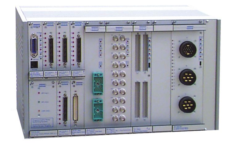
3 - SWITCHING BASICS

                                              SECTION 3

                                         Switching Basics

Relay Technology................................................................................. 3.3

    Reed Relays..................................................................................... 3.3

    Electro-Mechanical Relays............................................................. 3.6

    Mercury Wetted Relays................................................................... 3.7

    Edgeline Relays............................................................................... 3.8

    PIN Diode.......................................................................................... 3.8

    Solid State Relays........................................................................... 3.9

    Opto MOSFETs................................................................................ 3.9

    MEMs (Micro Electro-Mechanical Machines)................................ 3.10

    Latching Relays............................................................................... 3.11

    Safety Relay..................................................................................... 3.11

Switch Types......................................................................................... 3.12

                                                                                                              3.1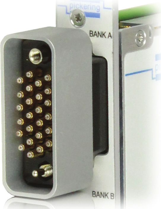
3 - SWITCHING BASICS

3.2
3 - SWITCHING BASICS

As mentioned in the previous section, a thorough understanding of your DUT will help select the
switch type needed. If your engineering department has released either a Theory of Operation or an
actual test strategy, then these SwitchMate guidelines can be applied to your tester configuration.

RELAY TECHNOLOGY
Because there is no one relay that will operate from millivolts to 1,000 volts at a frequency range of
DC to 18 GHz, there are many choices in switching. This next section will examine the relay types
used by all Switching System manufacturers. SwitchMate will highlight areas where each relay type
excels and where it may not be applicable.

Reed Relays
Reed Relays are deceptively simple devices in principle. The Reed Relay switch has two shaped
metal blades made of a ferromagnetic material (roughly 50:50 nickel/iron) and a glass envelope
that serves to both hold the metal blades in place and to provide a hermetic seal that prevents any
contaminants entering the critical contact areas inside the glass envelope. Most, but not all, Reed
Relay switches have open contacts in their normal state.
If a magnetic field is applied along the axis of the reed blades, the field is intensified in the reed
blades because of their ferromagnetic nature, the open contacts of the reed blades are attracted
to each other and the blades deflect to close the gap. With enough applied field the blades make
contact and an electrical connection is made.

                                Inert Gas                                   Contact Plating
                                                   No Axial Field
                            Glass Capsule
                                                                           Contact Gap

                             Reed Blade                                       Reed Blade

                               S Pole       Axial Magnetic Field Applied       N Pole

                                                    N Pole S Pole

                                          Fig. 3.1 - Reed Switch

Generating the Magnetic Field
A magnetic field needs to be created that is capable of closing the Reed Relay switch contacts. Reed
switches can be used with permanent magnets (for example to detect doors closing) but for many
Reed Relays the field is generated by a coil which can have a current passed through in response
to a control signal. The coil surrounds the reed switch and generates the axial magnetic field needed
to close the reed contacts.

                                                                                                             3.3
3 - SWITCHING BASICS
Inert Gas Contact Plating
Glass Capsule
Contact Gap
Reed Blade Reed Blade
Coil
Contact
Reed Blade
Fig. 3.2 - Generating a Magnetic Field
Different reed switches require different levels of magnetic field to close the contact, and this is
usually quoted in terms of the ampere turns (AT) – simply the product of the current flowing in the
coil multiplied by the number of turns. Again, this creates a great deal of variation in the Reed Relay
characteristics. Stiffer reed switches for higher power levels or high voltage switches with larger
contact gaps, usually require higher AT numbers to operate, so the coils require more power.
Protection Against Magnetic Fields
The fact that Reed Relays are magnetically operated causes a potential problem for users when they
are assembled in dense patterns on PCB’s.
The magnetic field required to close the reed blades flows through the nickel iron reed blades and
returns by field lines which are outside the Reed Relay body. If several relays are placed close together
the external field lines can be drawn by the neighboring reed blades and either reinforce of partially
cancel the field in the reed, changing the current needed to close or open the contact. This can in
some circumstances cause enough effect that the relay may either fail to close or open depending on
the magnetic polarity. Some manufacturers suggest arranging the relays in different polarity patterns
to mitigate the worst effect of the interaction, but this can become a complex compromise in dense
arrays of relays where there are many near neighbors.
A much more sensible approach is to include a magnetic shield in the reed relay package, an
approach used by Pickering Electronics for many years. The user is then free to use a layout pattern
that best suits the application.
Simplified illustration Simplified illustration
of the magnetic field showing cancellation
around a single Reed Switch & of magnetic fields
unscreened coil assembly due to adjacent
reed switch and unscreened reed
coil assembly relays
Unscreened assembly
Fig. 3.3 - Magnetic Interaction
3.43 - SWITCHING BASICS
Magnetic Shield
Coil
Field Lines Contained
by Magnetic Shield
Fig. 3.4 - Magnetic Shielding
Materials and Mechanical Life
The most reliable configuration for a Reed Relay is a Single Pole Single Throw (SPST) arrangement
(Form A). Single Pole Double Throw (SPDT) switches (Form C) can be made but the difficulty in
making them and the mechanical tolerance results in a product that generally has a lower life than
SPST parts. If lifetime is important it can be better to use two SPST relays and drive the coils to
synthesize a SPDT switch.
The mechanical life of a Reed Relay is still very long, typically more than 109 for Reed Relays
manufactured by Pickering Electronics for use in low current and medium current applications. The
reed switch features a hermetic seal and precise metal contact materials in the contact areas. The
magnetic field acts directly on the contact and there are few moving parts.
The hermetic seal also makes Reed Relays a good choice in hazardous environments since sparking
does not create a safety problem. The only moving part in the reed switch is the deflection of the
blades, there are no pivot points or materials trying to slide past each other. The contact area is
enclosed in a hermetically sealed envelope with either inert gasses, or in the case of high voltage
switches, a vacuum so the switch area is sealed against external contamination. This gives the reed
switch an exceptionally long mechanical life.
The materials used for the precious metal contact areas inside the glass envelope have a significant
impact on the Reed Relay switch (and therefore the relay) characteristics. Some materials have
excellent contact resistance stability; others resist the mechanical erosion that occurs during hot
switch events. Commonly used materials are ruthenium, rhodium and iridium– all of which are in the
relatively rare platinum precious metal group. Tungsten is often used for high power or high voltage
Reed Relays because of its high melting point. The material for the contact is chosen to best suit
the target performance - bearing in mind the material chosen can also have a significant impact on
manufacturing cost.
Reed Relays are supplied graded according to their cost and performance. Lower
quality commercial switches use Rhodium contacts that are less suited to switching
low- level signals because of the build-up of polymer films in the contact area of the reed.
Instrument grade Reed Relays, used on all Pickering Interfaces Reed Relay modules
unless otherwise stated, use sputtered ruthenium contacts that are suited for both
low-level and high-level switching. The contact areas do not exhibit the same film problems that
Rhodium Reed Relays have (or the more severe problems of electro-magnetic relays). If the
application is expected to include low-level switching where repeatable contact resistance is required,
then instrument grade ruthenium reeds should be specified.
For further information please refer to the Pickering ‘Reed RelayMate’ book.
3.53 - SWITCHING BASICS
Electro-Mechanical Relays
Moveable
Contact Normally
Open
Pivot
Common
Normally
Closed
Magnetic
Flux Energizing Coil
Fig. 3.5 - Electro-Mechanical Relay
Electro-Mechanical Relays (EMRs) are widely used in industry for switching functions and can often
be the lowest cost relay solution available to users. EMRs are comprised of an actuator or armature
moved by a magnetic field, the actuator in turn moving the position of a contact to make or break a
connection. The magnetic coil is physically separated from the contacts being moved to operate the
circuit. These are the most common form of relays available and can be used for a large range of
switching functions, including high power applications.
Most relays of this type are not hermetically sealed, and this can make them unsuitable for applications
where they are required to switch low level signals over long periods. Also, applications where there
are flammable vapors – such as testing an aircraft on the flightline – may not be a good choice for
EMRs because of their open frame construction. Contamination from the packaging process and
plastic out-gassing can result in partially insulating films appearing in the contact areas, leading
to increased contact resistance even if the contacts are designed with a wiping action. At higher
currents and voltages these problems do not occur because the switching action cleans the contact
and breaks down the films.
Some switches may include a specification for low level switching contact resistance that is worse
than when switching high-level signals. For switching low-level DC signals hermetically sealed
switches, such as Reed Relays, should be used.
EMRs are designed to have a wiping action when the contacts close, which helps to break small
welds and self-clean their contacts. This does lead to higher contact ratings but may also increase
wear on the contact plating.
EMRs can have much higher ratings and a lower contact resistance than Reed Relays because they
use larger contacts, Reed Relays are usually limited to carry currents of up to 2 or 3 Amps. Because
of their larger contacts, EMRs can also often better sustain current surges.
There are some notable differences between Reed Relays and EMRs which users should be aware
of:
•• Reed Relays generally exhibit much faster operation (typically between a factor of 5 and
10) than EMRs. The speed differences arise because the moving parts are simpler and
lighter compared to EMRs.
•• Reed Relays have hermetically sealed contacts which lead to more consistent switching
characteristics at low signal levels and higher insulation values in the open condition.
EMRs are often enclosed in plastic packages which provide a certain amount of
3.63 - SWITCHING BASICS
protection, but over time the contacts are exposed to external pollutants, emissions from
the plastic body, and oxygen and sulphur ingress.
•• Reed Relays have longer mechanical life (under light load conditions) than EMRs,
typically on the order of between a factor of 10 and 100. The difference is due to the lack
of moving parts in Reed Relays compared to EMRs.
•• Reed Relays require less power to operate the contacts than EMRs. The higher power
requirements limit the number of simultaneously relay closures on a module. This may
not be an issue for your application, but check the relay closure specification before you
purchase to be certain that it meets your needs.
Reed Relays and EMRs both behave as excellent switches. The use of high-volume manufacturing
methods often makes EMRs lower cost than Reed Relays, but within the achievable ratings of Reed
Relays, the Reed Relay has much better performance and longer life.
Mercury Wetted Relay
This is a type of Reed Relay with a film of liquid mercury retained by surface tension in the contact
area to provide the electrical contact. These switches, which typically need a specific mechanical
orientation to operate correctly, can have a long mechanical and electrical life. In the diagram here,
you can see a Change-Over (Form C) mercury wetted reed switch. The mercury pool is at the bottom
of the switch and to operate properly, it must be tipped vertical. The contact points are at the top.
A non-ferrous spacer is mounted on the normally closed contact. Without this it would not deflect to
the normally open contact in the presence of the magnetic field.
As to the way the mercury moves, the fixed blade that you see in the drawing forms a pump. When
the moving blade moves, it squeezes the mercury which then moves up the roughened surface of
the blade by capillary action to the contact.
But the presence of mercury in a relay causes environmental and health concerns. Their use is
strongly discouraged where alternatives are available, and in many countries, they are banned by
environmental legislation.
NC NO
(Normally Closed) (Normally Open)
Reed Reed NO
(Normally Open)
Reed
Non-Ferrous Glass Capsule
Spacer
UP
OFF Mercury travels
ON along moving blade
Moveable
Blade by capillary action
Operating
Position Mercury
Pump
Mercury
Inert Gas Pump
Mercury Pool
COM Reed COM Reed
Fig. 3.6 - Miniature Mercury-wetted Reed Switch (SPDT)
3.73 - SWITCHING BASICS
Edgeline Relays
Edgeline Relays are used in high frequency and microwave switches where a good 50 ohm
impedance is required to work at very high frequencies. The 50 ohm transmission line is formed
between the edge of a moving contact ribbon and the RF ground plane or metal wall. By tightly
controlling the gap between the edge of the ribbon and the wall, a good 50 ohm impedance can
be maintained regardless of the position of the ribbon. The gap involved is typically very small and
requires precision in the design and manufacture of the part.
Ground
Fixed
Contact
SPDT
Moving (Without Moving
Contact Contact Information)
Fixed
Contact
Edge Line Structure Microwave
Fig. 3.7 - Edgeline ofStructure
an EMR for of an EMR for RF Switching
RF Switching SPDT Switch
PIN Diode
A PIN diode is a special type of diode made with a P type, Intrinsic type and N type semiconductor
material. The structure results in diodes with a relatively long carrier lifetime. If PIN diodes are
forward biased and used at frequencies well above the specifications, they behave as resistors,
the resistance being dependent on the forward current. This allows them to be used as switches for
some RF and microwave applications, but at lower frequencies they become non-linear and behave
as conventional diodes.
Cathode
Diode Circuit
n+ Symbol
n
P-N Junction p+
Anode
Electrode
Fig. 3.8 - PIN Diode Structure
3.83 - SWITCHING BASICS
Solid State Relays
SIGNAL
g D
S
+
VG
S
g D
SIGNAL
Fig. 3.9 - Solid State Relay using Two N Channel MOSFETs
with an Isolated Gate Drive
Solid State Relay refers to a class of switches based on semiconductor devices. There are a large
variety of these switches available. Some, such as PIN diodes, are designed for RF applications
but the most commonly found solid-state devices that compete with Reed Relays are based on FET
switches. A solid-state FET switch uses two MOSFETs in series and an isolated gate driver to turn
the relay on or off. Some key differences compared to a Reed Relay include:
•• All Solid State Relays have a leakage current specification, consequently they do not
have as high an insulation resistance as EMRs and Reed Relays. The leakage current
is also non-linear. The on resistance can also be non-linear, varying with load current.
•• There is a compromise between capacitance and path resistance, relays with low path
resistance have a large capacitive load (sometimes measured in nF for high capacity
switches) which restricts bandwidth and introduces capacitive loading. As the capacitive
load is decreased the FET size has to decrease and the path resistance increases. The
capacitance of a solid-state FET switch is considerably higher than a Reed Relay.
•• Reed Relays are naturally isolated by the coil from the signal path as the coil is wound
around the reed switch. Solid state relays have an isolated drive incorporated into the
relay.
•• Solid State Relays can operate faster and more frequently than Reed Relays.
•• Solid State Relays can have much higher power ratings.
•• In general Reed Relays behave much more like perfect switches than Solid State Relays
because they use mechanical contacts.
Opto MOSFETS
Another type of Solid-State Relay is the Opto MOSFET (Optically Coupled MOSFET). In certain
applications, they are popular replacements for reed relays. These devices are relatively slow in
operation, but they feature very good voltage isolation because of the optical coupling. While the
Opto MOSFET operation may seem similar to Photocouplers (Also known as an optocoupler or
opto-isolator), it is important to note that Photocouplers only conduct DC in the output, while the Opto
MOSFET conducts AC and DC signals. Generally, the operating speed of photocouplers is rated in
microseconds, while that of Opto MOSFETs are rated in milliseconds.
3.9Photocoupler Sequence
3 - SWITCHING BASICS
Photocoupler Sequence
1 2 3
1 2 3
Fig.Opto-coupled MOSFET Sequence
3.10 - Photocoupler (Make-type
Operation contact)
Sequence
Opto-coupled MOSFET Sequence (Make-type contact)
1 2 3
1Fig. 3.11 - Opto-coupled MOSFET
2 Operation Sequence 3(Make-type Contact)
In the drawing here, you see the difference between a standard Photocoupler and an Opto MOSFET.
On the Photocoupler, when the LED is lit, the photodiode (Or a phototransistor) reacts and a current
flows from the collector to the base, forward biasing the transistor which then passes current from the
Collector through the Emitter. In the case of the Opto MOSFET, when the LED is lit, the photovoltaic
cells charge the gate capacitance to increase the gate-source voltage, turning on the MOSFETs in
the case of a make-type contact.
MEMs (Micro Electro-Mechanical Machines)
MEMs switches are fabricated on silicon substrates where a three-dimensional structure is micro-
machined (using semiconductor processing techniques) to create a relay switch contact. The contact
can then be deflected using either a magnetic field or an electrostatic field. For optical MEMs, mirrors
are used in place of switch contacts.
Much has been written about the promise of MEMs switches, particularly for RF switching, but
availability in commercially viable volumes at the time of this writing is very limited. The technology
challenges involved have resulted in a number of vendors involved in MEMs failing and either ceasing
to trade or closing down their programs. It should be noted that MEMs have had reasonable success
in testing fiber optic based systems.
Like Reed Relays, MEMs can be fabricated so the switch part is hermetically sealed (either in a
ceramic package or at a silicon level) which generally leads to consistent switching characteristics at
low signal levels. However, MEMs switches have small contact areas and low operating forces which
frequently leads to partial weld problems and very limited hot switch capacity.
The biggest advantage of MEMs relays – if they can be made reliable - is their low operating power
and fast response. The receive/transmit switch of a mobile phone for example has long been a target
for MEMs developers.
3.103 - SWITCHING BASICS
However, at their present stage of development, it seems unlikely MEMs will compete in the
general market with Reed Relays because the developers tend to concentrate on high value niche
opportunities and military applications.
Fig. 3.12 - MEMs Relay Structure
Latching Relays
Latching Relays have two or more stable positions for the contacts when power is not applied. To
change the state of a relay, a coil has a voltage transiently applied to it with a defined duration.
Latching Relays can be used for applications where minimization of control power (coil current) is
critical or where a power failure requires the switch to be left in the state it was set to until power is
restored. The latter case needs careful design to avoid transient change instructions as the power
fails. The latching mechanism usually relies on a magnet to provide the latching function.
Latching Relays are generally not used in modern software controlled test systems because the
software may not have direct knowledge of the relay state, particularly at power on. Some latching
relays can have extra contacts to provide a direct indication of the contact position.
Safety Relay
Also known as a force guided contact relay, this type of relay is designed with two or more contact
sets (poles) and the mechanical design is such that if one contact on one pole fails to change position
because of a weld, the other contact on another pole cannot close the corresponding contact. The
mechanical design usually relies on forces being applied to close to the contacts.
3.113 - SWITCHING BASICS
SWITCH TYPES
SPST (Single Pole Single Throw) (Can be 1 Form A or Form B)
No connection
Common
Fig. 3.13 - SPST Switch
Form A switches are open circuit with no power applied to the coil.
Form B switches are closed when no power is applied to the coil.
SPDT (Single Pole Double Throw) (1 Form C)
Normally open
Common
Normally closed
Fig. 3.14 - SPDT Switch
Form C switches have two possible outputs from input.
DPST (Double Pole Single Throw) (Can be 2 Form A or Form B)
No connection
Common
No connection
Common
Fig. 3.15 - DPST Switch
Two switches operated by the same control, each switch either being open circuit (no connection) or
connected to an output.
3.123 - SWITCHING BASICS
DPDT (Double Pole Double Throw) (2 Form C)
Normally open
Common
Normally closed
Normally open
Common
Normally closed
Fig. 3.16 - DPDT Switch
Two switches operated from the same control, each switch having an output connection for the
normally open and normally closed contacts.
Absorption Switches
50 Ohms
Output
Input
Output
50 Ohms
Fig. 3.17 - Absorption Switch
A switch where the contacts that are not being used are terminated in 50 ohms. This avoids the
presence of transmission lines that are not correctly terminated and the resonant structures they can
generate. It requires the presence of other (embedded) switches that connect the load to the unused
contacts but may not be shown on the equivalent circuit.
3.134 - PLATFORMS
SECTION 4
Platforms - What is Best?
Introduction........................................................................................... 4.3
PXI.......................................................................................................... 4.4
LXI.......................................................................................................... 4.4
USB........................................................................................................ 4.5
Other Platforms.................................................................................... 4.6
Should You Build Your Own Switching System?.............................. 4.8
4.14 - PLATFORMS 4.2
4 - PLATFORMS

When an engineer is designing a functional test system, the goal is to design and integrate the best
system in terms of measurement accuracy, throughput, and budget. One key bit of advice here: DO
NOT attempt to build your system with just one platform type. In this section “Platform” is defined as
the mechanical/electrical standards PXI, LXI, and USB.
It is important to note that it is not necessarily required to keep all instrumentation and switching in
the same platform – there are advantages to a hybrid solution, especially in the switching section of
the test system. This section will present an overview of the three most popular platforms used for
switching today, the advantages of each in various switching applications, and provide some basic
questions to ask as you integrate any test system. Also discussed will be the pros and cons of DIY
– Do It Yourself - or building a switching platform from scratch.
Of course, simply reading this won’t make you an expert, but the information provided will arm you
with enough knowledge to search for more details and ask the right questions.

Which Platform Is Best?
Now that the questions to ask about relay and switch types are understood, you need to determine the
best platform for the switching in your test system. Remember that, thanks to advances in software
and test system architecture, many different platform types play well together, enabling you to select
the best platform for your switching, power supplies, and instrumentation without regard to whether
they will work together. So, select the best platform based on performance, budget, and availability.
The first questions to ask regarding platform type depend on how you are structuring your test
system and include:
    •• Switching Only? Is a chassis with just switching advantageous to your design?
    •• Interface to Test Controller – How do you anticipate connecting all the test elements
       together? Is latency an issue for your test program?
    •• Voltage Isolation – If you are dealing with high voltage, do you need a level of isolation
       between the switching and the instrumentation?
    •• Remote/Distance Control – How close to the host Central Processing Unit (CPU) will the
       switching be located?
    •• Product Availability – Do you have vendors available that can support you with Commercial
       Off-The-Shelf (COTS) products? How long will they provide support?
    •• Vendor Support – Do you feel that your switching vendor of choice has the products and
       the support infrastructure to make you successful?
    •• Single Vendor Solution – Are you OK with dealing with a solution that is only available
       from one vendor?

                                                                                                     4.3
4 - PLATFORMS
PXI
In this platform, several companies are committed to PXI switching. At this time, Pickering Interfaces
is the market leader, with more than a thousand choices. Other companies with switching include
National Instruments, Keysight and Marvin Test.
Fig. 4.1 - PXI Chassis
Because there are multiple companies selling switching, there are regular new product introductions,
giving you more choice. This breadth of choice means that new systems and upgrades are easily
replicated with minimal effort.
Switching density has progressed greatly in recent years. It is now possible to get up to 528
cross-points on a PXI module that occupies just one chassis slot, potentially saving valuable slot
count for other instruments.
PXI is highly dependent on Windows and the PC (Linux extensions were recently added). This has its
good side and its bad side. In terms of switching in large applications requiring multiple PXI chassis,
power sequencing is an issue. If you do not power these chassis in the correct order, the PC may
not be able to enumerate the buses – this has the potential to lock up your PC or adversely affect the
discovery process.
LXI
Similar to PXI, LXI Ethernet has several switching vendors, making for a great many choices.
It should also be noted that both PXI and VXI switching platforms can also be LXI compliant, which
allows switch modules to be sited in a separate chassis to the test instrumentation. The transformer
coupling of Ethernet provides voltage isolation from the rest of the test system.
Fig. 4.2 - LXI Microwave Multiplexer (2U)
Generally, many LXI switching systems are ideal for solutions needing diverse and highly integrated
switching. This includes large I/O counts and high power. The mechanical freedom of LXI switching
allows for a wide variety of solutions that would not easily fit in other modular platforms.
LXI’s Ethernet interface is simple to use and maintain. Localized intelligence provides freedom from
the power sequencing issues previously mentioned. Built-in software drivers speed the initial starting
and install process of a test system integration.
4.44 - PLATFORMS
If your testing requires switching remote from a host PC, LXI and Ethernet assures control of your
switching in the next room or around the world.
USB
This platform is being seen more frequently in test. USB is now as widely adopted as Ethernet in
PCs. The latest specification, USB 3.0, is more robust than previous versions and also much faster.
The downside is there are few choices in USB switching at this time, although it is anticipated that
this will change in the coming years.
Fig. 4.3 - 4-Slot USB/LXI Modular Chassis
Like LXI, USB can be used for remote data acquisition, although not as distant as LXI. We find that
USB switching is seen as complementary to USB Data Acquisition in many applications.
In small benchtop applications, USB switching is simple to install and use.
The downside is that most USB switching platforms lack a locking connector, so any strain relief
needed must be addressed by the test engineer.
So How Do You Choose?
As we stated earlier, no one platform easily fits all applications. In general terms, LXI excels at:
•• High Power, Current or Voltage Switching. This is because of the physically large relays
and connectors that do not fit well in PXI.
•• Microwave Switching, again because of the size of large microwave switches with
coaxial interconnection.
•• Switching Remote from the Controller. Ethernet control reaches a long way, across a
building or around the world.
•• LXI’s local intelligence allows for simple recovery from power interruptions.
•• For applications requiring a variety of switching types, there are standalone LXI chassis
that can accept PXI switch modules.
•• If your company has made a corporate mandate to using LXI for all test applications,
there are solutions to meet most switching needs.
•• Finally, in very complex applications, the internal processor of an LXI device relieves
host CPU overhead, which can reduce the test times.
PXI also has its advantages:
•• For compactness, PXI makes it easier to include switching and instrumentation in a
single chassis.
4.54 - PLATFORMS
•• The high interface speed of PXI makes the instrumentation portion of your test system
much more efficient.
•• Because PXI is Windows-based, you normally deal with a single software environment.
•• For compactness and portability, the PXI chassis can have the application controller and
switching in a single chassis.
•• Finally, PXI switching is best implemented with a diverse mix of different switching
functions, mostly small to medium I/O count.
USB:
Similar to LXI, remote testing with USB is easily implemented. Also, the internal processor relieves
host CPU overhead for very complex applications, much the same as LXI.
Because USB is ubiquitous and has a very reasonable integration cost, low-cost test systems are
easily implemented in USB. For industrial PC applications, USB switching saves the limited slot
count in the PC for instrumentation. It can also move electrical switching noise outside of the PC,
making it easier to make measurements.
Other Platforms
Besides the platforms described in this section, there are other platforms in the market. At present
they are less popular for switching but you may want to consider them.
GPIB – General Purpose Interface Bus, also known by the instrumentation standard number IEEE
488 – This instrumentation standard has been in place for more than 40 years and is still used today.
The GPIB Standard is an 8-bit parallel communications standard. Maximum data rates are up to
8 Megabytes/second (IEEE 488.1), which is more than adequate for switching. But that data rate
gets progressively slower when many instruments are connected to the bus. Several companies,
including Pickering, still manufacture GPIB based switching systems, but for the most part, they are
older designs and tend to be expensive.
Fig. 4.4 - GPIB Modular Chassis
PCI – The Peripheral Computer Interconnect was developed by Intel in the 1980s. Available in
32-bit or 64-bit configurations, with either a 32 MHz or 66 MHz clock, the maximum data rate is up to
533 Megabits per second. The PCI bus was superseded by the multi-Gigabit PCI Express. Because
switching does not require this kind of bandwidth, it has remained available in Conventional PCI. This
bus standard is no longer available on standard desktop PCs, but remains popular on large industrial
PCs.
4.64 - PLATFORMS
Fig. 4.5 - A Range of PCI Cards
Proprietary Designs – There are several companies making switching in form factors unique to
them. Because each product is only available from one company, unlike standards such as PXI
and LXI, careful consideration should be made to ensure that they can address your switching
needs. Examples of proprietary switch products include the SIMRC line from Pickering Interfaces,
small (16 relays maximum) PCBs designed to be installed in a test fixture and controlled serially.
Other examples include the National Instruments CompactRIO®, which is a ruggedized system that
combines Ethernet control and local processing with modular, conditioned I/O modules, and can
control up to 64 relays in one chassis. Also, there is UEI’s (United Electronic Industries) Cube™
and RACKtangle™ chassis. These products are Ethernet-controlled and support a wide variety of
switching boards from UEI for general switching applications as well as the company’s analog and
digital I/O and avionics interfaces.
Fig. 4.6 - SIMRC (Pickering Interfaces)
Fig. 4.7 - CompactRIO (NI)
4.74 - PLATFORMS
Fig. 4.8 - CUBE (UEI)
DIY – Should You Build Your Own Switching System?
Back in the early days of functional test, most switching systems were built from scratch because
there were few choices available. So test engineers needed to innovate. Fast forward to today and,
even with the broad choice of COTS switching on the market, there are still some companies that
build their own switching systems. This test strategy tends to be implemented in emerging countries
that have lower salaries than the rest of the world, but there are exceptions.
This is not to say that you should not design your own switching. Rather, it should be pointed out
where it can be cost effective and it is important to make you aware of the potential challenges. In the
end, your decision should be based on cost, complexity, and time to market.
•• KISS (Keep It Simple Switching) If your switching requirements are extremely simple –
e.g., a few SPST relays to simulate DUT switches, High Current Input Power only, etc.
– there is little reason not to think about building up a set of relays on a simple PCB or
breadboard. There are relay driver modules available in PXI and USB, making the job
of controlling them from software relatively simple. If you have to work with high input
power, requiring a rather large contactor, DIY is a good strategy because these types of
switches do not fit well into a modular test format.
•• Applications – There are times when your application is so unique that a COTS
solution is just not good enough. So when looking at specifications of the signals you
will switch, acceptable insertion losses, and where the switching needs to be located,
we recommend that you talk to as many different switching vendors as possible before
making this choice.
•• Managing Your Costs – It is often thought that internal labor is “free”, so your cost of
switching development is lower than COTS solutions. If that is how your Accounting
folks see direct labor, then go ahead. But that is happening less often in modern industry
environments. So be sure you keep these costs in mind.
•• Time To Market – How long before your test system is to be implemented on the
production floor? Unless you have a very large staff to throw at a project, switching
system development can be as tedious as any new product design. As stated above, a
very simple switching development can be a no-brainer for internal development. But the
more complex it is, the more time you need to allocate.
4.84 - PLATFORMS
•• Protection Against Magnetic Fields – If you are new to switching system
design, the following information can be very important. The fact that relays
are magnetically operated can cause a potential problem for users when they
are assembled in dense patterns on PCBs, especially if you are designing with
Reed Relays.
For example, the magnetic field required to close the Reed Relay blades flows
through the nickel iron reed blades and returns by field lines which are outside
the Reed Relay body. If several relays are placed close together, the external
field lines can be drawn by the neighboring reed blades and either reinforce or
partially cancel the field in the reed, changing the current needed to close or
open the contact. This can, in some circumstances, cause enough effect that
the relay may either fail to close or open depending on the magnetic polarity.
Some manufacturers suggest arranging the relays in different polarity patterns
to mitigate the worst effect of the interaction, but this can become a complex
compromise in dense arrays of relays where there are many near neighbors.
A much more sensible approach is to include a magnetic shield in the Reed
Relay package, an approach used by Pickering Electronics for many years.
The user is then free to use a layout pattern that best suits the application.
The approach has the added benefit of improving the coil efficiency since it
concentrates the magnetic field lines closer to the reed switch body, shortening
the magnetic field length outside the reed blades and creating a larger field
for a given number of ampere turns in the coil. Lower coil operating currents
make coil driving simpler and improves other parameters like thermoelectric
EMF generation.
•• Support – Once your test system is ready, where will it be deployed? If the
answer is some other country, be prepared for support issues. All major COTS
test instrument and switching manufacturers have field support staff and can
resolve most test systems problems under warranty. In the case of a custom
switch system, your company is responsible. So, for example if your company
designs a switching system in the US and it is deployed to Malaysia, count on
late night phone calls and remote diagnostics.
•• Documentation – Custom-designed switching too often has minimal
documentation because most of the engineer’s time was dedicated to the
functional project and besides, the engineer knows what he built and how it
works! But explain that to an engineer overseas, especially if the designer has
left the company.
4.95 - MIGRATING SWITCHING FROM LEGACY SYSTEMS
SECTION 5
Migrating Switching from Legacy Systems
What is VXI?.......................................................................................... 5.3
What are Your Options?....................................................................... 5.4
Specifications....................................................................................... 5.4
Mass Interconnect versus Cable Connections to the DUT.............. 5.5
Software................................................................................................ 5.5
5.15 - MIGRATING SWITCHING FROM LEGACY SYSTEMS 5.2
5 - MIGRATING SWITCHING FROM LEGACY SYSTEMS

There comes a time in the life cycle of a test system when it becomes obsolete. This may be because
the product it was testing is no longer manufactured. More likely, the problem may be that the
instruments or switching system became obsolete, so test engineering can no longer support the
applications should a test system failure occur. This is a very pressing problem today, especially in
the aerospace and defense industries. Aircraft and weapon systems are used for a very long time.
For example, the US Air Force’s B-52 was designed and built in the 1950’s and yet those aircraft are
still being used and upgraded. An ATE system in this segment of the market is expected to support
applications for 15 years, 20 years, and even longer!
For the military and aerospace industries, many of the legacy systems are VXI-based. Developed
in the 1980s, the aerospace and defense industries were early adopters of modular test platforms.
One of the first successes was VXI and it has served these industries very well for more than
30 years. Now as VXI test systems become obsolete, test system developers look to PXI as the next
generation modular platform for their industries.
In this section, we will focus on migrating VXI-based switching to a PXI platform. If you are migrating
other platforms like GPIB, the thought process is similar.

What Is VXI?
VME eXtensions for Instrumentation (VXI) is an open standard platform for automated test based
on the modular VME computer bus. Introduced in 1987, this modular chassis-based architecture
reduced the size and increased the performance of high-end test systems. VXI systems provided
higher data transfer rates and real-time performance not possible with rack-and-stack systems, and
were principally successful in the military and aerospace markets.

                 Fig. 5.1 - VXI Chassis with Modules and Blanking Panel
In the past, VXI was proven to be a popular architecture with the military, their prime contractors,
and commercial ATE systems integrators. In 1999, according to Prime Data, the total yearly sales
of VXI Modules and VXI-based Standard Systems were estimated at $750 Million. Prime Data was
forecasting a 16% growth in the VXI market in 2000, and continued growth through 2004.
At that time, approximately 1200 VXI products were available from 80 test equipment vendors.
Checking on www.vxibus.org, today only 9 companies still manufacture VXI modules. VXI is now
more than 30 years old and many of the leading test and measurement companies are no longer
supporting the standard.

                                                                                                   5.3
5 - MIGRATING SWITCHING FROM LEGACY SYSTEMS
VXI still has a strong offering in Data Acquisition. But in switching, there are only two switching
vendors left and no new product introductions in years.
What Are Your Options?
VXI defined three module sizes – B, C, and D. C-size modules were the most popular for ATE
systems. The PXI specification primarily describes a 3U implementation. There is a 6U specification,
but very few PXI Systems Alliance (PXISA) Members adopted it. Dimensions of C-size VXI compare
to 3U PXI as follows:
C-size VXI 3U PXI
Height 9.2 in 3.9 in
Depth 13.4 in 6.3 in
Fig. 5.2 - VXI and PXI Size Differences
Clearly, there is more real estate in a VXI module. Also, a single-slot VXI module has a width
specification of 1.2 inches (also referred to as 6 HP) while a single slot 3U PXI module is only
0.8 inches wide (4 HP). So larger components will require a multiple slot PXI module.
It is obvious that you cannot pack the switching of a C-size VXI module into a PXI module without
occupying more than one slot … at least on the surface.
So, if I am going to migrate a test system from VXI to PXI, what do I need to know?
Specifications
The first thing to do is analyze your present test system and the applications it is required to test. It
is possible that the switching you have in VXI is overkill in terms of current, voltage, and even relay
count. If so, when specifying PXI modules, you might be able to select smaller, lower power modules
which can save money on your test budget. But this cannot be assumed to work. So, the questions
to ask are:
•• What is the maximum voltage to be switched?
•• Will the signals be hot or cold switched?
5.45 - MIGRATING SWITCHING FROM LEGACY SYSTEMS
•• What is the maximum current to be carried?
•• How much power must be dissipated in each switching channel?
•• What is the maximum frequency of any signal in the switching module?
•• Will this PXI-based migration be required to test newer applications? If that is the case,
you may need more switching than was available in the previous VXI-based system. So,
you will either need to plan for more switching hardware or at least allocating additional
slots in a PXI chassis for future expansion.
•• What are the configuration sizes needed? By that, we mean the number of individual
relays required, the channel count of the multiplexer, and the matrix size? Remember
that your VXI system may have more switching channels than is necessary.
Do Your Homework
Now that you have a clear understanding of what you need, you can research the PXI vendor
offerings. Pickering Interfaces offer a cross reference table from their PXI offerings to match most of
the popular VXI switch modules from the major manufacturers on their web site. It is likely that other
PXI manufacturers offer cross references as well. Check with your vendor of choice.
Mass Interconnect Versus Cable Connections to the DUT
Depending on the method of interfacing your test system to the DUT, migrating to a PXI-based switch
system could be relatively easy. If your test system uses a Mass Interconnect (explained in Section
7), the migration is relatively simple. This is because all the connections to the DUT will be the same
as before by interfacing to the Mass Interconnect. It is the other side of the Mass Interconnect that
will change. All that is needed are small adapter cables or pull-throughs to go from the PXI switch to
the Mass Interconnect.
If your test system uses cables to connect to the DUT, these will all have to be replaced or at least be
rewired, because in almost every instance, the connectors on a PXI module will not be the same as
those on the equivalent VXI module. Because VXI modules were much wider than PXI modules, the
VXI vendors took advantage of the added space and used larger and often more robust connectors.
Software
Fortunately, there was a push towards software standardization in the early 1990s. The VXI
P&P (VXIplug&play Systems Alliance) was an organization whose members shared a common
commitment to end-user success with open, multivendor VXI systems. The alliance accomplished
major improvements in ease of use by endorsing and implementing common software standards
and practices, beyond the scope of the VXIbus specifications. These standard frameworks gave
end-users “plug & play” interoperability at both the hardware and system software level. The
VXIplug&play Systems Alliance merged with the IVI (Interchangeable Virtual Instruments)
Foundation in 2002. So, much of the software standards are still applicable. See Figure 5.3 (IVI
System Architecture). It is worth noting that IVI drivers do not replace VISA, and typically use VISA
as the I/O Library for the IVI driver to send commands.
If your VXI-based test programs were generated under the guidelines of the VXI P&P, specifically the
VISA Layer, much of your code can be reused.
5.55 - MIGRATING SWITCHING FROM LEGACY SYSTEMS
User Application Test Program Test System Setup
VB - LabVIEW - C/C++/C# - etc. Maintenance Application
IVI-C IVI-COM COM
IVI Class Class
(C or COM) Session
Driver Compliant IVI
Custom Specific Factory
Config
IVI-C Class Driver &
Specific Server
Compliant Class
Driver
Specific Driver Interface
I/O Library
Instrumentation Hardware
IVI System Architecture
Fig. 5.3 - IVI System Architecture
IVI did not take off quickly in the early days. The reason was mostly competitive – If I write an IVI
Driver for my customers, what is to stop them from replacing my product with a competitor’s when
the code will work for both vendors?
Another reason that slowed adoption was test speed. In 2002, PCs were not nearly as fast as
today’s models. Adding an extra layer of software could potentially slow things down because CPU
resources were tasked with extra code.
That last reason is not as critical in today’s test environment. But if you are migrating older test code,
you will need to see if an IVI layer was incorporated into the test strategies.
5.6You can also read