Stress analysis in oral obturator prostheses, part II: photoelastic imaging - SPIE ...
←
→
Page content transcription
If your browser does not render page correctly, please read the page content below
Stress analysis in oral obturator
                 prostheses, part II: photoelastic
                 imaging

                 Aldiéris Alves Pesqueira
                 Marcelo Coelho Goiato
                 Emily Vivianne Freitas da Silva
                 Marcela Filié Haddad
                 Amália Moreno
                 Abbas Zahoui
                 Daniela Micheline dos Santos

Downloaded From: https://www.spiedigitallibrary.org/journals/Journal-of-Biomedical-Optics on 19 Nov 2021
Terms of Use: https://www.spiedigitallibrary.org/terms-of-use
Journal of Biomedical Optics 19(6), 066012 (June 2014)

                Stress analysis in oral obturator prostheses,
                part II: photoelastic imaging
                Aldiéris Alves Pesqueira,a Marcelo Coelho Goiato,a,* Emily Vivianne Freitas da Silva,a Marcela Filié Haddad,b
                Amália Moreno,a Abbas Zahoui,c and Daniela Micheline dos Santosa
                a
                    University Estadual Paulista, Araçatuba Dental School, Department of Dental Materials and Prosthodontics, Araçatuba 16015-050, SP, Brazil
                b
                    Federal University of Alfenas–Unifal, Dental School, Department of Restorative Dentistry, Alfenas 37130-000, MG, Brazil
                c
                    University Sagrado Coração, Faculty of Dentistry, Department of Oral Biology, Bauru 17011-160, SP, Brazil

                               Abstract. In part I of the study, two attachment systems [O-ring; bar-clip (BC)] were used, and the system with
                               three individualized O-rings provided the lowest stress on the implants and the support tissues. Therefore, the
                               aim of this study was to assess the stress distribution, through the photoelastic method, on implant-retained
                               palatal obturator prostheses associated with different attachment systems: BOC—splinted implants with a
                               bar connected to two centrally placed O-rings, and BOD—splinted implants with a BC connected to two distally
                               placed O-rings (cantilever). One photoelastic model of the maxilla with oral-sinus-nasal communication with
                               three parallel implants was fabricated. Afterward, two implant-retained palatal obturator prostheses with the
                               two attachment systems described above were constructed. Each assembly was positioned in a circular polari-
                               scope and a 100-N axial load was applied in three different regions with implants by using a universal testing
                               machine. The results were obtained through photograph record analysis of stress. The BOD system exhibited
                               the highest stress concentration, followed by the BOC system. The O-ring, centrally placed on the bar, allows
                               higher mobility of the prostheses and homogeneously distributes the stress to the region of the alveolar ridge and
                               implants. It can be concluded that the use of implants with O-rings, isolated or connected with a bar, to reha-
                               bilitate maxillectomized patients allows higher prosthesis mobility and homogeneously distributes the stress to
                               the alveolar ridge region, which may result in greater chewing stress distribution to implants and bone tissue. The
                               clinical implication of the augmented bone support loss after maxillectomy is the increase of stress in the attach-
                               ment systems and, consequently, a higher tendency for displacement of the prosthesis. © 2014 Society of Photo-Optical
                               Instrumentation Engineers (SPIE) [DOI: 10.1117/1.JBO.19.6.066012]

                               Keywords: photoelastic imaging; dental implant; palatal obturators; maxillofacial prosthesis.
                               Paper 140219R received Apr. 5, 2014; revised manuscript received May 29, 2014; accepted for publication Jun. 4, 2014; published
                               online Jun. 27, 2014.

                1      Introduction                                                                the stress distribution on the implants and the support tissues.
                Maxillary defects may lead to serious injury in anatomical struc-                  The photoelastic analysis of stress was introduced in dentistry
                                                                                                   by Noonan in 1949. After this work, the photoelastic method has
                tures that have a role as denture-supporting area in edentulous
                                                                                                   received increased attention in the field of restorative dentistry.14
                patients, decreasing retention and stability of prostheses,1–3 and
                                                                                                   This technique is based on the optical property that certain
                drastically decreasing the quality of life of its users.1,4–10
                                                                                                   transparent plastics exhibit when submitted to a state of
                Therefore, the palatal obturator prostheses became an important
                                                                                                   stress/strain, resulting in changes of the refractive index (or opti-
                treatment choice for the patient’s rehabilitation process.1,3,8,10–12
                                                                                                   cal anisotropy) and, consequently, in changes of color.14–21
                    However, the stability and the retention of those prostheses
                                                                                                       Currently, the photoelastic method has been used to assess
                are a challenge and require distinctive treatment planning.1,2
                                                                                                   the stress in implant-supported prostheses and the bone tissue
                Also, it is known that maxillary defects jeopardize the obturator
                                                                                                   by several studies,1,3,4,14–25 which simulated the mechanical-
                prostheses biomechanics because of the presence of leverage
                                                                                                   clinical situations presented in this type of rehabilitation.
                forces that drastically increase stress on bone support during
                                                                                                   These situations include: fit and misfit framework, description
                chewing.1,3,8,13                                                                   of the sequence of fringes formation, size and location of misfit
                    It is known that the mechanism of stress distribution to the                   at the implant-abutment interface, overdenture attachment sys-
                implants and the bone tissue is a critical issue that affects implant              tem, implants placed in the posterior edentulous jaw (fabricated
                success or failure, because that is how the mechanical stress is                   with photoelastic material), parallel and tilted implants,
                transferred from the implant to the bone. Currently, photoelastic-                 attachment systems of facial prosthesis, connection system of
                ity is one of the most used experimental techniques to study the                   cylindrical implant, and different types of connectors in
                behavior of stress distribution in implantodontology.6                             implant-tooth union, among others.15,16,18,20–22
                    Many studies have used information and data extracted from                         So, the use of attachment systems associated with implants is
                experimental, analytical, and computational models, among                          a new alternative to rehabilitate maxillectomized patients since it
                them the photoelastic method, with the purpose of analyzing                        provides higher retention and stability of the prostheses1,3,6,23–33
                                                                                                   and improves the patient’s assurance and confidence.1,3,6,8,9,11–13

                *Address all correspondence to: Marcelo Coelho Goiato, E-mail: goiato@foa
                 .unesp.br                                                                         0091-3286/2014/$25.00 © 2014 SPIE

                Journal of Biomedical Optics                                              066012-1                                              June 2014   •   Vol. 19(6)

Downloaded From: https://www.spiedigitallibrary.org/journals/Journal-of-Biomedical-Optics on 19 Nov 2021
Terms of Use: https://www.spiedigitallibrary.org/terms-of-use
Pesqueira et al.: Stress analysis in oral obturator prostheses, part II: photoelastic imaging
Based on the results of these two studies,1,19 an interest arose The obturator prostheses were adapted to the photoelastic
in how these systems would work in biomechanical combination models with the attachment system. Each assembly (photoelas-
(BOC and BOD systems) in prostheses supported by three par- tic model/attachment system/prostheses) was positioned in a
allel implants. The hypothesis of this study is that both attach- circular polariscope into a glass with mineral oil, to minimize
ment systems provide similar stress distribution on the implants the refraction of white light (Photoflood 500 WGE Lighting
and the support tissues, regardless of the location. General Electric, Cleveland, Ohio) that uniformly focuses on
the recipient with the photoelastic model. Thus, a 100-N load
at 10 mm∕s was applied on the opposite side of the communi-
2 Materials and Methods cation in the region of incisive, canine, and first molar, by using
An experimental maxillary model with oral-sinus-nasal commu- a universal testing machine (EMIC-DL 3000, São Paulo, São
nication was used to reproduce one laboratorial model confec- Paulo, Brazil). The images were recorded by a digital camera
tioned with type IV dental stone (Durone, Dentsply Ind Com (Nikon D80, Nikon Corporation, ChitodaKu, Tokyo, Japan) and
Ltd., Petrópolis, Rio de Janeiro, Brazil). Through this model, transferred to a computer for qualitative analysis by Adobe
the photoelastic model with implants was obtained. For this, Photoshop CS version 8.0.1 software (Adobe Systems, San
three implant analogues (Neodent, Curitiba, Paraná, Brazil) Jose, Califórnia).1,3,9
were inserted in the laboratorial model, which had three perfo- Photographic records of all models were analyzed to verify
rations that were parallel to each other (regions of upper incisive, the direction and intensity of stress based on qualitative analysis.
canine, and first molar). After perforation and insertion using a That analysis consisted of the higher the N (fringes order) and
the number of fringes, the greater the stress intensity.
paralelometer, the implant analogues were fixed with Duralay
Additionally, the closer the fringes are to each other, the higher
acrylic resin (Duralay Reliance Dental MFG Co. Worth,
the stress concentration is.1
Illinois), so that the analogue platform remains at the same
The photoelasticity has some limitations as does any labora-
level of the alveolar ridge.
tory study. The qualitative photoelastic analysis was used in the
Squared transfer posts (Neodent, Curitiba, Paraná, Brazil)
present study. Therefore, it is not possible to quantify the stress
were placed and screwed to the analogues. These transfers
magnitude and the results usually do not present statistical
were connected to each other with dental floss and Duralay
analysis.
acrylic resin. The laboratorial model with placed transfers
The isochromatic fringes are described by their concentration
was duplicated with fluid silicon (Sapeca Artesanato, Bauru,
and intensity (qualitative analysis), depending upon the order
São Paulo, Brazil) in order to obtain its negative impression.
(N) and number of fringes. Fringes that are closer to each
After the silicon had set, the transfer screws were removed,
other present higher stress concentrations.
obtaining a negative impression with placed transfers. The stress distribution is observed through isochromatic
External hexagon implants with 3.75-mm diameters and 13- fringes, whose order is counted based on fringe transition:15,34,35
mm lengths (Neodent, Curitiba, Paraná, Brazil) were attached
and screwed to these transfers. At this moment, the correct posi- Fringe order N ¼ 0 (black zone)
tion of the implants to transfers was checked and the negative
Fringe order N ¼ 1 (red-blue transition)–low intensity
impression was filled with PL-2 photoelastic resin (Vishay
Measurements Group Inc. Raleigh, North Carolina, USA), Fringe order N ¼ 2 (red-green transition)–median
manipulated and tooled according to the manufacturer’s instruc- intensity
tions. Later, the assembly (negative impression + photoelastic Fringe order N ¼ 3 (green-pink transition)–high intensity
resin) was stored in a chamber under 40 pounds of pressure
To facilitate, the analysis was divided according to the num-
to avoid bubbles during resin polymerization. After the PL-2
ber of fringes with high intensity (green-pink transition) and to
resin polymerization, the model was carefully separated from
the stress distribution area. All images were evaluated by the
the negative impression and sanding and polishing procedures
same person.1,3,9
were performed with fine grit sandpapers (600, 800, 1200,
1500).1,3,9
Concerning the models, a photoelastic model was confec- 3 Results
tioned (standardized measures) for each type of implant and Based on the images, a greater number of high stress fringes was
prosthetic restoration (crowns with standard heights). Several observed in the BOD system, followed by the BOC system
samples were not made because the model response (fringe (Table 1). Additionally, it was possible to observe that the asso-
patterns), regarding the type of applied load, will always be ciation of the O-ring (centrally or distally placed on the bar) with
the same within the methodology that was used.
The laboratorial model with implant analogues was used to
Table 1 Number of photoelastic fringes with high intensity (green-
fabricate the obturator prostheses. Two prostheses were fabri- pink transition) according to the crowns in which the load was applied.
cated using different attachment systems: BOC—splinted
implants with a bar connected to two centrally placed
O-rings, and BOD—splinted implants with a bar-clip (BC) Axial load
connected to two distally placed O-rings (cantilever). Crown
The obturator prostheses were fabricated with artificial
teeth with 20 deg of cusp inclination (Trilux Vipi Produtos Attachment system 16 13 11
Odontológicos, Pirassununga, São Paulo, Brazil) and colorless
heat-polymerized resin (Vipi Produtos Odontológicos, BOC 4 4 6
Pirassununga, São Paulo, Brazil) so as to not influence the BOD 5 5 5
results of the images obtained during the method application.1
Journal of Biomedical Optics 066012-2 June 2014 • Vol. 19(6)
Downloaded From: https://www.spiedigitallibrary.org/journals/Journal-of-Biomedical-Optics on 19 Nov 2021
Terms of Use: https://www.spiedigitallibrary.org/terms-of-usePesqueira et al.: Stress analysis in oral obturator prostheses, part II: photoelastic imaging
Fig. 1 Stress distribution in the model with splinted implants with a bar connected to centrally placed
O-rings (BOC).
the bar allows lower stress to the support tissues than the isolated In part I of the study,1 two attachment systems (O-ring; BC)
BC system, described in part I of the study.1 were used. Also, the system with three individualized O-rings
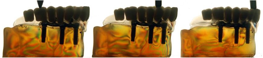
In the models with implants, regardless of the attachment provided the lowest stress on the implants and the support tis-
system, a higher number of fringes was located at the apical sues. Additionally, in another study, Pesqueira et al.19 assessed
region of the implant to which the load was applied (Figs. 1 the stress distribution through the photoelastic method, on
and 2). implant-retained palatal obturator prostheses over two parallel
implants and one tilted using four different attachment systems
4 Discussion (three individualized O-rings, OR; bar clip, BC; O-rings
The hypothesis that both attachment systems provide similar positioned at the center of the bar, BOC; O-rings positioned
stress distribution on the implants and the support tissues, in distal cantilever, BOD) and conventional obturator prostheses
regardless their location, was not accepted, since the BOD sys- (without implants). The authors concluded that the BOC and
tem exhibited higher stress concentration than the BOC system the BOD systems presented intermediate stress values when
(Table 1). compared with the BC and the OR systems.
The results showed a greater number of high stress fringes on In our study, the use of O-rings connected with a bar (Fig. 1)
the BC system, followed by the BOD system, the BOC system, or with a BC (Fig. 2) decreased stress values, when comparing it
the O-ring system (OR), and the conventional obturator prosthe- to an isolated BC system (part I of the study1). These results
ses (without implants), respectively (Table 1; Pesqueira et al.1). corroborate with some studies,14,18,19 which consider that the
Despite the obturator prostheses without implants having attachment system with a bar connected to distally placed
exhibited the lowest stress values, as observed in part I of O-rings produced lower stress values than other systems.
the study,1 it is known that the maxillary defects jeopardize Studies13,27,29,30,31 justify that the O-ring attachment systems
the obturator prostheses biomechanics, drastically decreasing homogeneously distribute the stress over the bar and have
their stability and retention during chewing.1–8,13 great resilience. In our opinion, the BOD system exhibited
Therefore, the use of implants as support components of higher stress values than the BOC system because the cantilever
prostheses to partial or total maxillectomized patients’ rehabili- extension allows higher leverage in that region which, conse-
tation has been growing, since it provides higher retention and quently, increases the stress. In addition, the clip presence in
stability of the prostheses, reducing their movement.1–4,9,10,13 the center of the bar also adds stress to the system.
However, a distinctive planning is determinant for clinical suc- It is important to note that several factors must be considered
cess and has to be based on the patient’s specific anatomic con- when selecting the attachment system: the available surface area,
ditions,8 implants, and attachment systems to be selected.23–33 the need for prostheses support, the retention level to be obtained,
According to our study, the attachment system directly and the stress distribution to the implants and the bone tissue.11,23
influences stress distribution to the implants and the support The differences among them are in material type, components’
tissue, and each one has different stress values. resilience and shape, and type of association between attachment
The knowledge of stress transmitted by the assembly—pros- systems, implants, and remaining teeth. Each one of the attach-
theses, attachment system, and implant—to the bone tissue is ment systems has different biomechanics.13,28
essential for its correct biomechanical work. The excess of stress The clinical implication of the augmented bone support loss
transmitted to the implants and attachment systems may cause after maxillectomy is the increase of stress in the attachment
system fatigue and consequent fracture on the implant compo- systems and, consequently, a higher tendency for the prosthe-
nents and overload them and the bone tissue, which would also sis’s displacement. Concerning the limitations of this study,
result in a possible loss of osseointegration, causing prostheses the photoelastic analysis has some restrictions because
instability and retention loss.1,3,9 it is an indirect technique that requires models of similar
Fig. 2 Stress distribution in the model with splinted implants with a bar connected to distally placed
O-rings (cantilever) (BOD).
Journal of Biomedical Optics 066012-3 June 2014 • Vol. 19(6)
Downloaded From: https://www.spiedigitallibrary.org/journals/Journal-of-Biomedical-Optics on 19 Nov 2021
Terms of Use: https://www.spiedigitallibrary.org/terms-of-usePesqueira et al.: Stress analysis in oral obturator prostheses, part II: photoelastic imaging
reproduction to oral structures so they can be compared. The 10. M. C. Goiato et al., “Patient satisfaction with maxillofacial prosthesis.
limit of external force to be applied must be considered. That Literature review,” J. Plast. Reconstr. Aesthet. Surg. 62(2), 175–180
(2009).
force should not exceed the resistance threshold of the photo-
11. B. Lethaus et al., “Surgical and prosthetic reconsiderations in patients
elastic material, which could alter the results or cause its with maxillectomy,” J. Oral. Rehabil. 37(2), 138–142 (2010).
break. Additionally, although some materials used for making 12. J. Irish et al., “Quality of life in patients with maxillectomy prostheses,”
experimental models present an elastic modulus similar to the Head Neck. 31(6), 813–821 (2009).
bone tissues, they cannot emulate actual models, lacking differ- 13. F. Keyf, “Obturator prostheses for hemimaxillectomy patients,” J. Oral.
entiation between cortical and trabelular bone, for example, Rehabil. 28(9), 821–829 (2001).
which alters the magnitude of the stress produced by loading. 14. M. Sevimay et al., “Three-dimensional finite element analysis of the
effect of different bone quality on stress distribution in an implant-
However, the stress location and magnitude are slightly modi-
supported crown,” J. Prosthet. Dent. 93(3), 227–234 (2005).
fied when compared to real models.15,18,22 15. A. A. Caputo, “Stress analysis,” Seminário de Biomateriais, Science
Section. Abstracts, UCLA School of Dentistry, Los Angeles (1993).
16. K. Akça, M. I. Fanuscu, and A. A. Caputo, “Effect of compromised
5 Conclusion cortical bone on implant load distribution,” J. Prosthodont. 17(8),
We conclude that: 616–620 (2008).
17. R. Tiossi et al., “Comparison of the correlation of photoelasticity and
• The attachment system directly influenced stress distribu- digital imaging to characterize the load transfer of implant-supported
restorations,” J. Prosthet. Dent., pii: S0022-3913(13)00372-7, [Epub
tion of implant-retained palatal obturator prostheses. ahead of print] (2014).
• The O-rings, centrally placed on the bar, homogeneously 18. A. Pesqueira et al., “The use of stress analysis methods to evaluate the
distribute the stress when compared with a BC connected biomechanics of oral rehabilitation with implants,” J. Oral Implantol.
40(2), 217–228 (2014).
to distally placed O-rings (cantilever). 19. A. A. Pesqueira et al., “Stress analysis in oral obturator prostheses over
• When using the implants to rehabilitate maxillectomized parallel and tilted implants: photoelastic imaging,” J. Biomed. Opt.
patients, the O-rings—isolated or connected with a bar– 18(10), 106009 (2013).
20. S. J. Sadowsky and A. A. Caputo, “Effect of anchorage systems and
allow higher prostheses mobility and homogeneously dis-
extension base contact on load transfer with mandibular implant-
tribute the stress to the alveolar ridge region, which may retained overdentures,” J. Prosthet. Dent. 84(3), 327–334 (2000).
result in greater chewing stress distribution to the implants 21. M. C. Goiato et al., “Methods used for assessing stresses in buccomax-
and the bone tissue. illary prostheses: photoelasticity, finite element technique, and extens-
ometry,” J. Craniofac. Surg. 20(2), 561–564 (2009).
22. K. T. Ochiai et al., “Photoelastic stress analysis of implant-tooth
connected prostheses with segmented and no segmented abutments,”
Acknowledgments J. Prosthet. Dent. 89(5), 495–502 (2003).
The authors would like to thank the National Council for 23. V. A. Barão et al., “Finite element analysis to compare complete denture
and implant-retained overdentures with different attachment systems,”
Scientific and Technological Development (CNPq, Brazil)
J. Craniofac. Surg. 20(4), 1066–1071 (2009).
for PhD scholarship to the first author, and the Foundation 24. G. Meniccuci et al., “Mandibular implant-retained overdenture: finite
for Support to Research of the State of São Paulo (FAPESP, element analysis of two anchorage systems,” Int. J. Oral Maxillofac.
Brazil) for the financial support of this investigation. Implants. 13(3), 369–376 (1998).
25. J. A. Porter, V. C. Petropoulos, and J. B. Brunski, “Comparison of
load distribution for implant overdenture atachments,” Int. J. Oral
References Maxillofac. Implants. 17(5), 651–662 (2002).
26. M. C. Cehreli et al., “A systematic review of marginal bone loss around
1. A. A. Pesqueira et al., “Stress analysis in oral obturator prostheses:
implants retaining or supporting overdentures,” Int. J. Oral Maxillofac.
imaging photoelastic,” J. Biomed. Opt. 18(6), 061203 (2013).
Implants. 25(2), 266–277 (2010).
2. S. M. Ortegon, J. W. Martin, and J. S. Lewin, “A hollow delayed
27. G. Celik and B. Uludag, “Photoelastic stress analysis of various reten-
surgical obturator for a bilateral subtotal maxillectomy patient clinical
tion mechanisms on 3-implant-retained mandibular overdentures,”
report,” J. Prosthet. Dent. 99(1), 14–18 (2008).
J. Prosthe. Dent. 97(4), 229–235 (2007).
3. M. C. Goiato et al., “Photoelastic analysis to compare implant-retained
28. R. Kenney and M. W. Richards, “Photoelastic stress patterns produced by
and conventional obturator dentures,” J. Biomed. Opt. 17(6), 061203
implant-retained overdentures,” J. Prosthet. Dent. 80(5), 559–564 (1998).
(2012).
29. V. A. Barão et al., “Effect of different mucosa thickness and resiliency
4. M. C. Goiato et al., “Photoelastic analysis of stress distribution in differ-
on stress distribution of implant-retained overdentures-2D FEA,”
ent retention systems for facial prosthesis,” J. Craniofac. Surg. 20(3),
Comput. Methods Programs Biomed. 92(2), 213–223 (2008).
757–761 (2009).
5. O. C. Dilek and E. Tezulas, “A mini implant-supported obturator appli- 30. K. M. Lyons, J. Beumer, and A. A. Caputo, “Abutment load transfer by
cation in a patient with partial maxillectomy due to tumor: case report,” removable partial denture obturator frameworks in different acquired
Oral Surg. Oral Pathol. Oral Radiol. Endod. 103(3), e6–e10 (2007). maxillary defects,” J. Prosthet. Dent. 94(3), 281–288 (2005).
6. B. Bagis, E. Aydoğan, and U. Hasanreisoğlu, “Rehabilitation of a con- 31. Z. Ben-Ur, C. Gorfil, and A. Shifman, “Anterior implant-supported
genital palatal defect with a modified technique: a case report,” Cases J. overdentures,” Quintessence Int. 27(9), 603–606 (1996).
1(1), 39 (2008). 32. M. Tokuhisa, Y. Matsushita, and K. Koyano, “In vitro study of mandibu-
7. M. C. Goiato et al., “Retention systems to implant-supported craniofa- lar implant overdenture retained with ball, magnet, or bar attachments:
cial prostheses,” J. Craniofac. Surg. 20(3), 889–891 (2009). comparison of load transfer and denture stability,” Int. J. Prosthodont.
8. E. Bedrossian and P. I. Brånemark, “Systematic treatment planning pro- 16(2), 128–134 (2003).
tocol for patients with maxillofacial defects: avoiding living a life of 33. M. Daas et al., “A complete finite element model of a mandibular
seclusion and depression,” Atlas Oral Maxillofac. Surg. Clin. North implant-retained overdenture with two implants: comparison between
Am. 20(1), 135–158 (2012). rigid and resilient attachment configurations,” Med. Eng. Phys. 30(2),
9. C. T. Nguyen, C. F. Driscoll, and D. P. Coletti, “Reconstruction of a 218–225 (2008).
maxillectomy patient with an osteocutaneous flap and implant-retained 34. J. F. Brodsky, A. A. Caputo, and L. L. Furstman, “Root tipping: a
fixed dental prosthesis: a clinical report,” J. Prosthet. Dent. 105(5), photoelastic-histopathologic correlation,” Am. J. Orthod. 67(1), 1–10
292–295 (2011). (1975).
Journal of Biomedical Optics 066012-4 June 2014 • Vol. 19(6)
Downloaded From: https://www.spiedigitallibrary.org/journals/Journal-of-Biomedical-Optics on 19 Nov 2021
Terms of Use: https://www.spiedigitallibrary.org/terms-of-usePesqueira et al.: Stress analysis in oral obturator prostheses, part II: photoelastic imaging
35. R. A. Markarian et al., “Stress distribution after installation of fixed Marcela Filié Haddad received her PhD degree from the Araçatuba
frameworks with marginal gaps over angled and parallel implants: a Dental School, University of the State of São Paulo, Brazil. She is
photoelastic analysis,” J. Prosthodont. 16(2), 117–122 (2007). currently a postdoctoral researcher in the same university and a pro-
fessor in the Federal University of Alfenas.
Aldiéris Alves Pesqueira received his PhD degree from Araçatuba
Amália Moreno received her MS degree from the Araçatuba Dental
Dental School, University of the State of São Paulo, Brazil. Currently,
School, University of the State of São Paulo, Brazil. Currently she is a
he is a professor in the Department of Dental Materials and
postgraduate student from the same university.
Prosthodontics, Araçatuba Dental School, University of the State of
São Paulo, Brazil.
Abbas Zahoui is a postgraduate student from the Faculty of
Dentistry, University Sagrado Coração—USC, Bauru, SP, Brazil.
Marcelo Coelho Goiato received his PhD degree from the Dental
School of Piracicaba, State University of Campinas, Brazil. Currently,
Daniela Micheline dos Santos received her PhD degree from the
he is a professor in the Department of Dental Materials and
Araçatuba Dental School, University of the State of São Paulo,
Prosthodontics, Araçatuba Dental School, University of the State of
Brazil. Currently, she is a professor in the Department of Dental
São Paulo, Brazil.
Materials and Prosthodontics, Araçatuba Dental School, University of
the State of São Paulo, Brazil.
Emily Vivianne Freitas da Silva received her DDS degree from the
Bahia Federal University. Currently she is a postgraduate student
from the Araçatuba Dental School, University of the State of São
Paulo, Brazil.
Journal of Biomedical Optics 066012-5 June 2014 • Vol. 19(6)
Downloaded From: https://www.spiedigitallibrary.org/journals/Journal-of-Biomedical-Optics on 19 Nov 2021
Terms of Use: https://www.spiedigitallibrary.org/terms-of-useYou can also read