Stable epidermal electronic device with strain isolation induced by in situ Joule heating
←
→
Page content transcription
If your browser does not render page correctly, please read the page content below
Wang et al. Microsystems & Nanoengineering (2021)7:56
                                    https://doi.org/10.1038/s41378-021-00282-x
                                                                                                                                                               Microsystems & Nanoengineering
                                                                                                                                                                                                www.nature.com/micronano

                                     ARTICLE                                                                                                                                                    Open Access

                                    Stable epidermal electronic device with strain
                                    isolation induced by in situ Joule heating
                                    Zihao Wang1,2, Qifeng Lu1, Yizhang Xia3, Simin Feng1, Yixiang Shi1, Shuqi Wang1, Xianqing Yang1, Yangyong Zhao1,
                                    Fuqin Sun1, Tie Li1 and Ting Zhang1 ✉

                                      Abstract
                                      Epidermal electronics play increasingly important roles in human-machine interfaces. However, their efficient
                                      fabrication while maintaining device stability and reliability remains an unresolved challenge. Here, a facile in situ Joule
                                      heating method is proposed for fabricating stable epidermal electronics on a polyvinyl alcohol (PVA) substrate.
                                      Benefitting from the precise control of heating locations, the crystallization and enhanced rigidity of PVA are restricted
                                      to desired areas, leading to strain isolation of the active regions. As a result, the electronic device can be conformably
                                      attached to skin while showing negligible degradation in device performance during deformation. Based on this
                                      method, a flexible surface electromyography (sEMG) sensor with outstanding stability and highly comfortable
                                      wearability is demonstrated, showing high accuracy (91.83%) for human hand gesture recognition. These results imply
                                      that the fabrication method proposed in this research is a facile and reliable approach for the fabrication of epidermal
                                      electronics.
                  1234567890():,;
1234567890():,;
                  1234567890():,;
1234567890():,;

                                    Introduction                                                                                        including serpentine and accordion bellow shapes17–19.
                                       Flexible electronics are considered the next revolution in                                       Metal-based devices take advantage of their electrical
                                    the electronics industry due to their potential applications                                        conductivity compared with their polymer-based coun-
                                    in areas unreachable with rigid devices1–6. As a vital part of                                      terparts. However, the brittleness and modulus mismatch
                                    flexible electronics, epidermal electronics can be essen-                                            between metals and soft substrates is a challenge that
                                    tially applied in the area of health monitoring and human-                                          cannot be ignored in device design and fabrication20,21.
                                    machine interfaces (HMIs)7,8. To achieve highly comfor-                                               Strain isolation, a strategy to protect the active region by
                                    table wearability and outstanding device performance, a                                             modifying the intrinsic rigidity contrast between metal-
                                    stretchable and ultraflexible epidermal electronic device is,                                        based devices and soft substrates, offers a possible solution
                                    by tuning the material modulus and device structures, is                                            to overcome the above problems22–25. Usually, delicate
                                    desirable to achieve conformable contact with human                                                 mechanical design is required to achieve reliable strain iso-
                                    skin4,9. Generally, there are two strategies to fabricate                                           lation, which includes assembling inorganic components on
                                    epidermal electronics. The first method is to fill polymer                                            surface relief patterns rather than on flat surfaces26,27,
                                    composites with conductive materials, such as carbon                                                embedding hard platforms within soft substrates22, and
                                    nanotubes, graphene, and metal nanowires10–16, while the                                            inserting a soft layer between devices and substrates25.
                                    other method uses metals with designed structures,                                                  However, there the use of strain isolation strategies in device
                                                                                                                                        manufacture is considerably complex. For example, strain
                                                                                                                                        isolation typically demands the use of transfer printing, in
                                    Correspondence: Ting Zhang (tzhang2009@sinano.ac.cn)
                                    1
                                     i-lab, Key Laboratory of Multifunctional Nanomaterials and Smart Systems,                          which active components in a designed layout are deposited
                                    Suzhou Institute of Nano-Tech and Nano-Bionics (SINANO), Chinese Academy                            on a silicon wafer and then transferred onto an elastomeric
                                    of Sciences (CAS), 398 Ruoshui Road, Suzhou, Jiangsu 215123, P. R. China
                                    2                                                                                                   substrate in two separate steps28. Due to complexities in the
                                     Nano Science and Technology Institute, University of Science and Technology
                                    of China, 96 Jinzhai Road, Hefei, Anhui 230026, P. R. China                                         preparation process, it is still a challenge to fabricate a thin
                                    Full list of author information is available at the end of the article

                                    © The Author(s) 2021
                                                        Open Access This article is licensed under a Creative Commons Attribution 4.0 International License, which permits use, sharing, adaptation, distribution and reproduction
                                                        in any medium or format, as long as you give appropriate credit to the original author(s) and the source, provide a link to the Creative Commons license, and indicate if
                                    changes were made. The images or other third party material in this article are included in the article’s Creative Commons license, unless indicated otherwise in a credit line to the material. If
                                    material is not included in the article’s Creative Commons license and your intended use is not permitted by statutory regulation or exceeds the permitted use, you will need to obtain
                                    permission directly from the copyright holder. To view a copy of this license, visit http://creativecommons.org/licenses/by/4.0/.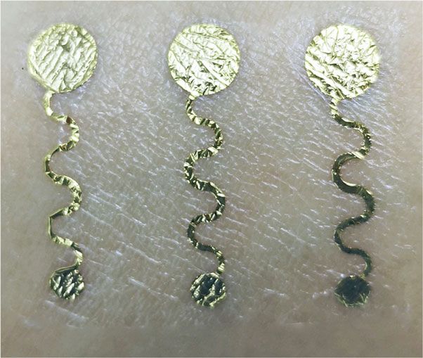
Wang et al. Microsystems & Nanoengineering (2021)7:56                                                                 Page 2 of 10

(submicrometer) metal-based device to satisfy the condition        when exposed to moisture, as shown in Fig. 1d. When the
of conformal contact7,29.                                          treatment temperature is lower than 100 °C, the PVA sub-
  Herein, inspired by the mechanism of strain isolation,           strate completely dissolves in water. As the temperature
we propose a facile in situ Joule heating method to                increases, the swelling rate of the substrate decreases, and
directly fabricate stable epidermal electronics on PVA             almost no swelling occurs when the annealing temperature
substrates. The intrinsic stiffness contrast in the polymer        reaches 170 °C. As a result, the thickness of the substrate
substrate obtained by Joule heating offers a simple yet            after swelling decreases with decreasing annealing tem-
robust mechanism without resorting to transfer printing.           perature, as indicated by the red curve in Fig. 1d. In addition,
With an in situ Joule heating treatment, programmable              as illustrated in Fig. 1e and Fig. S1, the modulus of the PVA
changes in the crystallinity distribution can be achieved in       membrane increases rapidly when the temperature reaches
the coplanar PVA substrate, resulting in a designed                100 °C and becomes saturated thereafter. All these results
swelling rate and stiffness of the treated membrane. When          indicate that it is possible to control the thickness and
the polymer substrate contact skin, the region without             Young’s modulus of PVA membranes by modulating the
treatment absorbs moisture from the skin, and the                  thermal treatment temperature. Figure 1f shows an example
membrane swells, resulting in a thinner substrate and              showing that after annealing at 130 °C for 30 min, the PVA
perfect adapting to skin folds. To demonstrate the                 membrane is able to conformably adapt to skin folds after
advantage of this method, metal-based surface electro-             absorbing moisture from the epidermis and environment.
myography (sEMG) sensors with low impedance, highly
comfortable wearability, and good conformal adhesion               Fabrication procedure of the metal layer on a PVA
properties were fabricated. In addition, human hand                membrane
gesture classification based on the fabricated sEMG sen-              Based on this, we fabricated a patterned metal layer
sors was implemented, and a high classification accuracy            on a PVA substrate and optimized the stress and
of over 91.83% was achieved.                                       modulus mismatch between the metal and PVA mem-
                                                                   brane through precise Joule heating treatment. As
                                                                   demonstrated in Fig. 2a, layers of polymethyl metha-
Results and discussion                                             crylate (PMMA) and PVA were initially spin-coated on
Properties of PVA membranes at different thermal                   a glass substrate and cured at 130 °C for 30 min. Then,
treatment temperatures                                             chromium (10 nm) and gold (100 nm) were deposited
  In this research, a nontoxic, easily processable, and bio-       on the substrate as a metal layer, which was patterned
compatible PVA membrane, was employed as the substrate.            by electron beam evaporation through a hard mask,
Previous reports indicated that the hydrogen bonds formed          followed by spin-coating another layer of PVA on top as
between PVA molecules could hinder crystallization of the          a protection layer. Afterward, a Joule heating process
membrane30; thus, a decrease in the swelling rate of PVA is        was carried out only on the PVA/metal layer/PVA area
associated with an increase in PVA crystallinity31. The            with a custom system, consisting of heating probes, a
crystallization of PVA can be enhanced by removing water           microscope, and a DC power supply, as shown in Fig.
through thermal treatment. Fig. 1a shows a schematic dia-          S2. After thermal treatment, the PVA membrane-
gram of the crystallization process during the thermal             sandwiched metal layer exhibits a high modulus and
treatment of PVA. At high temperature, the gradual loss of         loses its swelling property, while other areas without
water in the PVA membrane leads to a decrease in the               annealing can still absorb moisture and swell when
number of hydrogen bonds, and PVA crystallization occurs           exposed to a moisture-rich environment.
during the cooling process. By precise control of the thermal        Figure 2b shows the as-prepared patterned metal
treatment temperature, different degrees of PVA crystallinity      layer (metal line, 300 µm) on the same PVA membrane
can be realized, as indicated by the XRD patterns in Fig. 1b.      without thermal treatment. Clear cracks appear on the
The gradual decrease in the full width at half maximum             metal, and the metal line is destroyed (Fig. 2d). In
(FWHM) of the diffraction peak at 19.8° with increasing            contrast, the metal layer on the PVA membrane after
annealing temperature is an indicator of the improvement in        annealing remains intact, and the regions near the
crystallinity. In addition, the intensity of the absorption peak   metal show good swelling properties and can adhere
at 1141 cm−1, which is attributed to the asymmetric                conformably to arbitrary surfaces (Fig. 2c and e). After
stretching vibration of the C–C bond31,32, significantly            thermal treatment, the stiffness of the PVA substrate
increases with increasing annealing temperature, as illu-          increased, as reflected by its measured hardness
strated in Fig. 1c. These results confirm that the degree of        increase (Fig. 2f). These results are also consistent with
crystallinity of the PVA membrane can be precisely con-            the modulus change of PVA with thermal treatment at
trolled by tuning the thermal treatment temperature, thus          130 °C and 170 °C (Fig. 2g). In addition, thermal treat-
further influencing the swelling rate of the PVA membrane           ment of metal areas can decrease their strain. This can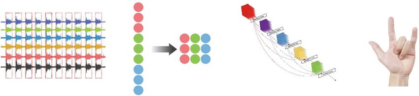
Wang et al. Microsystems & Nanoengineering (2021)7:56 Page 3 of 10
a
Crystal domain
Crystallinity increase
20 °C 170 °C
b c f
2.0
Dissolve
350 1.6
170 °C
μm)
PVA membrane
Swelling rate (%)
lntensity (a.u.)
150 °C 300
Thickness (μ
1.2
Swelling rate
130 °C 250
Thickness 0.8
100 °C 200
0.4
70 °C
150
30 °C Dissolve
100
10 20 30 40 50 30 70 100 130 150 180
2θ (deg) Thermal treatment temperature (°C) Absorb
d e 5000
moisture
No swelling
170 °C 4000
Swelling
Absorbance (%)
Modulus (MPa)
150 °C
130 °C 3000
100 °C
2000
70 °C Dissolve
1000
30 °C
0
4000 3500 3000 2500 2000 1500 1000 30 50 70 90 110 130 150 170
–1
Wavenumber (cm ) Temperature(°C)
Fig. 1 Properties of PVA at different thermal treatment temperatures. a Crystallinity of PVA increases with increasing heat treatment
temperature. b XRD spectra of PVA at different heat treatment temperatures. The gradual decrease in the FWHM for the diffraction peak at 22.7°
suggests an increase in the crystallinity of PVA. c IR spectra of PVA at different heat treatment temperatures. The increase in the band at 1141 cm−1,
which is attributed to symmetric C–C, in the FTIR spectra is another characteristic of PVA membrane treatment at different temperatures. d Changes
in the thickness and swelling rate of PVA membranes treated at different temperatures. The swelling rate decreases with increasing treatment
temperature, which is consistent with the XRD results. e The modulus of PVA increases with increasing treatment temperature. f PVA membranes
(thermal treatment at 130 °C) absorb moisture from the environment (such as skin and air), and the membrane can conformably contact skin
be explained by Hooke’s law: material, E is the modulus of the material and A is the cross-
sectional area of the material. As illustrated in Fig. 2h,
FN l without thermal treatment, the thickness of the PVA
Δl ¼
EA substrate decreases. Therefore, the metal layer in the active
region cannot be effectively protected by the PVA substrate,
where Δl is the elongation of the solid material, l is the and obvious cracks appear. However, when the substrate is
original length of the material, FN is the force applied to the annealed with the in situ Joule heating treatment, the PVA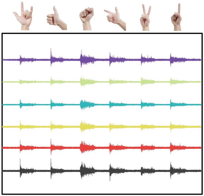
Wang et al. Microsystems & Nanoengineering (2021)7:56 Page 4 of 10
a Spin coating Spin coating E-beam evaporation
Au Au
Mask Au Mask
PVA PVA
PMMA PMMA PMMA
Glass Glass Glass
Release in acetone Thermal treatment Spin coating
PVA
PVA PVA
PVA Au PVA
Au PVA Au PVA
PVA PVA PVA
PVA PVA
PMMA PMMA
Glass Glass
Glass
b d f 0.60
0.55
Untreated
Untreated 0.50 Treated
Hardness (GPa)
0.45
0.40
0.35
0.30
0.25
0.20
0 80 160 240 320 400
Distance (μm)
c e g 70
60
Treated 50
Stress (MPa)
40
30
20
170 °C
10 130 °C
0.5 mm 100 μm
0
–10
0 3 6 9 12 15
Strain (%)
h i Treated Joule heating
Untreated
PVA Swelling Metal Swelling
Cracks No cracks
Fig. 2 Schematic diagram showing the fabrication procedure of a metal layer on a PVA membrane. a Fabrication process of patterning metal
layers on a PVA membrane. b The PVA membrane swells when exposed to a moisture-rich environment, and cracks appear for the metal line without
any heat treatment. c Negligible deformation of the metal line occurs when it is subjected to heat treatment. SEM images of d untreated and e heat-
treated metal lines. The influence of heat treatment on the hardness of the PVA substrate is shown in f, where a distance of 0 is the edge of the metal
line. g Modulus of the PVA membrane with thermal treatment temperatures of 130 °C and 170 °C. It is verified that the modulus of PVA surrounding
the Joule heating metal layer is enhanced but changes little in other areas. Schematic diagrams of the cross-section of a PVA membrane with a metal
layer. After absorbing moisture, h cracks appear on the metal layer without thermal treatment, but i the metal layer with thermal treatment remains
complete and protected by the lack of swelling of the PVA membrane
substrate in the active region does not significantly swell in the treated region both contribute to the decreased strain
when exposed to a moisture-rich environment, and no in the thermally treated area. Therefore, the thermal
cracks appear on the metal layer (Fig. 2i). The decreased treatment area can be protected by strain isolation, and
thickness of the untreated region and the increased modulus self-adhesion of the substrate is achieved after swelling.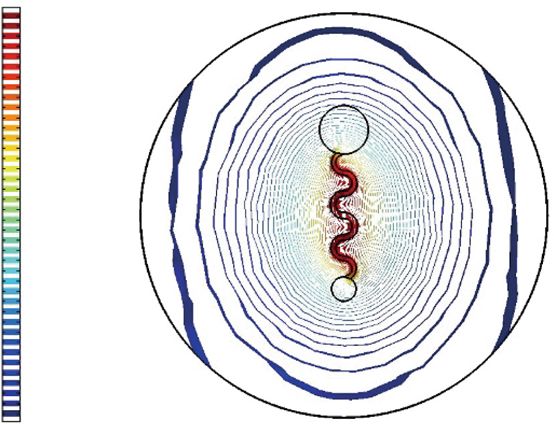
Wang et al. Microsystems & Nanoengineering (2021)7:56 Page 5 of 10
a b c
459.42 470
459.54
453.22 Straight
447.8
447.03 Serpentine
436.07 460
440.83
424.34
Temperature (°C)
434.63
412.61
428.43 450
400.87
422 .24
389.14
377.41 416.04
440
365.67 409.84
353.94 403.64
397.44 430
342.21
330.47 391.25
318.74 385.05 420
307.01 378.85
–7 –6 –5 –4 –3 –2 –1 0 1 2 3 4 5 6 7
Distance (mm)
d e 20 f 40
15% 8 Force
15 30% Resistance
10 6 30
Resistance (Ω)
5
Force (N)
R/R0(%)
4
0 20
2
–5
–10 0 10
–15
–2
–20 0
0 500 1000 1500 2000 0 1 2 3 4 5 6
Number of cycles Number of cycles
Fig. 3 Structural design and mechanical performance of the sEMG sensors. a, b Heat distribution isotherm diagrams for sEMG sensors with a
straight line and a serpentine metal line, respectively. A more uniform temperature distribution can be achieved for the serpentine metal line based
on simulations. c The difference in the temperature can reach 36 °C for the sensor with a straight design, which is ~20 °C higher than that of the
serpentine metal sensor. d Schematic illustration of an sEMG sensor with a PVA substrate. e Resistance change of the sEMG sensors under 15 and 30%
stretching on a skin replica for 2000 cycles. f A resistance change within 2 Ω is measured during each stretching cycle (30%)
Structural design and mechanical performance of the (Fig. 3d). A photograph and the structure design of the
sEMG sensors prepared sensor are shown in Figs. S5 and S6, respectively.
Based on the above results, sEMG sensors with long-term To investigate the stretchability of the sensor, we fixed the
reliability can be fabricated with the proposed method. In device on a Mark-10 digital force gauge and measured its
addition, to improve device performance, we applied the resistance fluctuation during stretching. When stretching
finite element method (FEM) to simulate the temperature the sensor to 15 or 30%, the resistance of the device for
field distribution and optimize the structural design of the both cases only changes within 3% after 2000 cycles
sensors. The temperature distribution of a straight-line (Fig. 3e). In addition, during a single stretching cycle with
sensor is shown in Fig. 3a, where the highest temperature a stretching rate up to 30% and a stretching force reaching
appears in the center and decreases rapidly when moving 3.8 N, the resistance change of this device is 2 Ω (Fig. 3f).
away from the center. A significant temperature difference These results indicate that this sensor can endure the
of ~35.6 °C between the center and margin areas is mea- impact of people’s daily actions; thus, stable sEMG signals
sured for the straight-line structure (black curve in Fig. 3c), can be obtained using this sensor.
which leads to a large difference in mechanical strength
among these areas. In addition, a large temperature differ- Electrical performance of the sEMG sensors
ence affects the swelling rate of the substrate and influences Next, we placed the sEMG sensor on skin in a moisture-
its adhesion to skin, thus degrading and damaging the metal rich environment and collected EMG signals (Fig. 4a). As
layer due to the bulging of the PVA substrate (Fig. S3). In expected, the PVA substrate absorbed moisture and
comparison, the temperature difference of the metal layer became thinner allowing the sensor to conformally attach
between the center and the ends for the serpentine structure to the skin (Fig. 4b) due to swelling of the membrane. As
design is only 14.7 °C, which is much lower than that of the illustrated in Fig. 4c, the sensor adapts well to skin folds,
straight structure (Fig. 3b and c). This observation was and no obvious cracks are observed.
further verified by experiments, where a temperature var- Benefitting from their excellent mechanical stability, the
iation of 15.8 °C was obtained, as shown in Fig. S4. sEMG sensors exhibit good electrical performance. First,
Based on the simulation results, we fabricated a impedance, which is an important factor that influences
serpentine-shaped sEMG sensor on a PVA substrate sEMG signals, was measured. Compared with commercial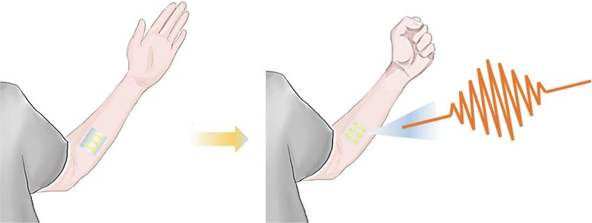
Wang et al. Microsystems & Nanoengineering (2021)7:56 Page 6 of 10
a
Absorb moisture EMG signal
b c
PVA substrate
Metal electrode
0.5 mm
d 600 e 3
0h
500 1h
2
2h
Impedance (kΩ)
400 3h
Amplitude (mV)
1
4h
300
5h
6h 0
200
7h
8h –1
100
0 –2
–100 –3
100 1000 10,000 100,000 0 2 4 6 8
Frequency (Hz) Time (h)
f 100 g 3
2
Impedance (kΩ)
Amplitude (mV)
80 1
0
60 –1
–2
40 –3
–1 0 1 2 3 4 5 6 7 8 9 1 5 10 40 70 100
Time (h) Cycles
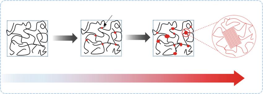
Fig. 4 Electrical performance of the sEMG sensors. a After absorbing moisture from the environment, the sensors can conformably fit skin folds and
record sEMG signals. b Image of the sEMG sensors attached to human skin. c SEM image of a sensor that has been peeled off of skin. The area circled in
red is the metal layer, which combines well with the substrate. d No significant increase in the impedance of the sensors is observed when attached to
skin for 8 h. e sEMG signals measured with the sensors. f No significant changes in the impedance of the sensors at 1 kHz are observed. g sEMG signals
for a series of muscle contractions followed by rest measured with the as-prepared sensors attached to the wrist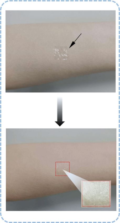
Wang et al. Microsystems & Nanoengineering (2021)7:56                                                          Page 7 of 10

gel sEMG sensors, the fabricated sEMG sensors exhibit          Conclusion
better long-term stability33, which is of great importance       In this work, strain isolation theory was applied to
in long-term monitoring29, despite a slight increase in        epidermal electronics, and a new method based on this
impedance. As shown in Fig. 4d–g, negligible changes in        theory was proposed to fabricate sEMG sensors on PVA
impedance are observed after 8 h of use. The decrease in       membranes. With the metal devices undergoing a pre-
impedance from 75 to 65 kΩ at a 1 kHz frequency in the         cise Joule heating process, the stiffness of the active area
first hour can be attributed to the initial adaptation of the   was enhanced, while the adhesion of the substrate was
sensor to skin folds. During the 8 h, the sensors were bent    not affected. The optimal structure of the sEMG sen-
100 times, and no significant degradation of the EMG            sors was designed using the FEM. The sensors showed
signals is observed. These results further verify the sta-     outstanding performance in terms of wearable comfort
bility of the device.                                          and stability compared with commercial gel sensors.
                                                               Furthermore, to demonstrate the potential application
Gesture classification of multichannel sEMG signals             of the sensors in HMIs, the sensors were shown to be
  To verify the advantages of the sEMG sensors, we             able to recognize the sEMG signals of human gestures
compared the recognition rate of captured signals              using machine learning algorithms with a high accuracy
between the prepared sEMG sensors and commercial               of 91.83%. These results indicate that this method
sEMG sensors. Eight sensors were wrapped around a              provides an idea to fabricate epidermal electronic
wrist at a sampling rate of 1000 Hz, among which six were      devices in an efficient but robust way.
test sensors and the other two were a reference sensor and
ground sensor. A volunteer was asked to repeatedly per-        Experimental section
form six defined gestures in sequence 100 times, and a          Preparation of the PVA membrane
total of 600 corresponding gesture signals were recorded.        A 12% PVA (PVA-124, Aladdin) solution was
  Then, PyTorch software, including a manual segmen-           obtained by dissolving PVA-124 in deionized water and
tation module, a data preprocessing module, and a clas-        stirring for 30 min at 100 °C. PMMA (P141443, Alad-
sifier module, was used to analyze and recognize gesture        din) solution was obtained by dissolving PMMA pow-
signals, as shown in Fig. 5a. The segmentation module          der in ethyl lactate (Aladdin) at a 30% weight ratio and
starts by manually labeling the peaks of the sEMG wave         stirring for 50 min at 150 °C. First, the PMMA solution
and subsequently obtains 4500 values as segmented ges-         (2 ml) was coated on a 2-inch glass substrate by spin
ture data. Then, the above 4500 values are compressed          coating (3000 rpm, 30 s) and baked at 70 °C on a hot
into a 64*64*6 matrix through the data processing mod-         plate for 10 min, which was used as a sacrificial layer.
ule. After that, the classifier module inputs the matrix into   Then, a PVA layer (2 ml) was coated on the PMMA
DenseNet10034. After 200 epochs of training, a classifier       layer by spin coating (4000 rpm, 30 s) and baked at
model and parameters based on sEMG gesture signals are         130 °C on a hot plate for 30 min.
obtained. Figure 5b presents the sEMG signals of different
hand gestures extracted through the six channels. The          Material properties
signal-to-noise ratio (SNR) of the sEMG signals during           XRD was performed to investigate the crystallinity of
the test time is illustrated in Fig. S7. With increasing       PVA before and after heat treatment (Bruker D8). FTIR
operation time, the SNR of the sEMG signals acquired by        spectra were collected via a Thermo Nicolet iN
the commercial sensors decreases from 24.3 to 6.5. In          10 spectrometers with a laser operating at 77 K in a
contrast, the SNRs of the sEMG signals acquired by the         liquid nitrogen environment. Tensile tests were carried
prepared sensor are within the range of 19.8–23.4. As          out using a universal material testing machine. A
shown in Fig. 5c, the recognition rate slowly increases as     hardness test was carried out by a nanoindentation
training progresses for both the commercial and fabri-         tester in continuous stiffness measurement mode. The
cated sensors in this experiment, and the recognition rate     distance between each test point was 80 µm, and the
becomes saturated at a certain value. This result indicates    depth limit of every test point was 300 nm.
that the model used in this research was convergent and
that overfitting was avoided.                                   Structural design of the sEMG sensors
  The accuracy for each individual test is presented in Fig.     The appropriate structure of the sEMG sensors was
5d. According to the statistical results, the average accu-    investigated by performing FEM and the AC/DC
racy rates for the commercial and fabricated sensors were      module and heat transfer module were required to
82.33% and 91.83%, respectively. The above results also        simulate electrical heat generation and heat transfer.
demonstrate that in the case of long-term use, the fabri-      Joule heating treatment models were established by
cated sensors degrade more slowly than commercial              drawing a geometric model of the sensor in simulation
sensors, resulting in a higher recognition rate.               software and defining boundary conditions to simulate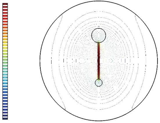
Wang et al. Microsystems & Nanoengineering (2021)7:56 Page 8 of 10
a
Data segmentation Processing Classification Gesture recognition
t
lnpu
1 H1
2 X1
H2
3 X2
4 1 4 7 H3
X3
5 2 5 8 H4
6 3 6 9 X4
7
1 2 3 4 5 6 7 8 9 10
8
9 DenseNet
b c
100
80
Accuracy (%)
60
40
20
1
Prepared sensor_Train Commercial sensor_Train
0 Prepared sensor_Test Commercial sensor_Test
2
0 20 40 60 80 100 120 140 160 180 200
Epoch
Channel
3 d
110 Epidermal sensor
Commercial sensor
4 100
Accuracy (%)
90
5 80
70
6 60
50
1 2 3 4 5 6 7 8 9 10
Test set number
Fig. 5 Gesture classification of multichannel sEMG signals. a Structure of the program. The sEMG signal is segmented into ten parts, and one
gesture is included in each part. Then, the data are processed into a 64*64 matrix. Next, the matrix is input into DenseNet to classify the gestures.
Finally, the gesture is recognized. b sEMG signals for six different gestures. c Training process of the data: the accuracy of the training increased as the
number of epochs increased. The accuracy of the epidermal sensor was higher than that of the commercial gel sensor. d Recognition accuracy with
different test sets. The accuracy of the prepared sensor was better than that of the commercial sensor while also being more stable
the real situation. The temperature distribution in the Characterization of the devices
model can be more uniform by optimizing the size (line The temperature distribution test was carried out by a
width, arc radius, etc.) of the model. thermocouple thermometer (Kaipusen TES 1310) with
the temperature probe fixed on the probe table. The
Fabrication of the sEMG sensors temperature distribution of the metal line was monitored
A metal mask was laminated on the PVA membrane, by moving the temperature probe to different places and
and Ti and Au layers with thicknesses of 10 nm and testing the temperature.
100 nm were deposited using E-beam evaporation (Ei- The mechanical performance was investigated using a
5z, ULVAC). The deposition rate was set at 1.5 Å Mark-10 digital force gauge. The details are as follows: the
per second. Then, another PVA layer was coated on the sEMG sensor was placed on a skin replica made of PDMS
metal as a protective layer (spin-coating, 3000 rpm, (Dow Corning Sylgard 184), the sensor was stretched to the
30 s), followed by annealing at 130 °C for 20 min. After programmed length (15 and 30%), and the impedance
that, a custom heating system was used to carry out the change of the sensor was investigated using a KEITHLEY
Joule heating process with an applied voltage of 8 V for 2602 instrument.
10 min. Finally, the PVA membrane with sEMG sensors Skin/electrode interface impedance measurements were
was peeled off from the glass by dissolving the PMMA taken using an electrochemical workstation (Gamry Refer-
in acetone (immersed in acetone at 60 °C for 20 min). ence 600+) with frequencies ranging from 100 to 105 Hz.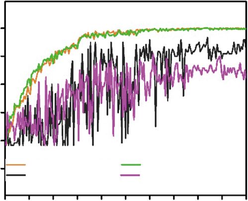
Wang et al. Microsystems & Nanoengineering (2021)7:56                                                                                                      Page 9 of 10

The spacing between each electrode was maintained at                                Supplementary information The online version contains supplementary
50 mm. EMG signals were recorded by multiplex bioelectric                           material available at https://doi.org/10.1038/s41378-021-00282-x.

data acquisition equipment (ZJE-II) at a sampling rate of
                                                                                    Received: 18 January 2021 Revised: 20 April 2021 Accepted: 30 May 2021
1000 Hz. Commercial sensors with diameters of ~50.5 mm
were purchased from Liveyai Medical, which is a traditional
Ag/AgCl gel electrode for disposable use.

Gesture recognition                                                                 References
                                                                                     1. Ko, H. C. et al. A emispherical electronic eye camera based on compressible
  Eight sensors were wrapped around a wrist in a ring, six of                            silicon optoelectronics. Nature 454, 748–753 (2008).
which provided valid signals; the sampling frequency was                             2. Kim, D. H. et al. Epidermal electronics. Science 333, 838–843 (2011).
1000 Hz. After one day of collection, the wearer repeated                            3. Nawrocki, R. A. et al. Self-adhesive and ultra-conformable, sub-300 nm dry
                                                                                         thin-film electrodes for surface monitoring of biopotentials. Adv. Funct. Mater.
one of the six gestures, each movement lasted for approxi-                               28, 1803279 (2018).
mately five seconds, and the same movement was repeated                               4. Wang, S. et al. Skin electronics from scalable fabrication of an intrinsically
ten times before changing to the next gesture. Ultimately,                               stretchable transistor array. Nature 555, 83–88 (2018).
                                                                                     5. Kwon, Y. T. et al. All-printed nanomembrane wireless bioelectronics using a
100 samples were collected for each gesture, reaching a total                            biocompatible solderable graphene for multimodal human-machine inter-
of 600 gesture samples. PyTorch was used to complete all                                 faces. Nat. Commun. 11, 3450 (2020).
experiments on a desktop computer with an NVIDIA 1060.                               6. Xie, Z., Avila, R., Huang, Y. & Rogers, J. A. Flexible and stretchable antennas for
                                                                                         biointegrated electronics. Adv. Mater. 32, 1902767 (2020).
As shown in Fig. 5a, to recognize the sEMG gesture signal,                           7. Ferrari, L. M. et al. Ultraconformable temporary tattoo electrodes for electro-
the program included a manual segmentation module, a                                     physiology. Adv. Sci. 5, 1700771 (2018).
data preprocessing module, and a classifier modul34e. The                             8. Jeong, J.-W. et al. Materials and optimized designs for human-machine
                                                                                         interfaces via epidermal electronics. Adv. Mater. 25, 6839–6846 (2013).
detailed steps of the segmentation module consist of first                            9. Lai, S. et al. Ultra-conformable organic field-effect transistors and cir-
manually annotating the peaks of the sEMG wave and                                       cuits for epidermal electronic applications. Org. Electron. 46, 60–67
extracting the subsequent 4500 values as the segmented                                   (2017).
                                                                                    10. Koo, J. H. et al. Wearable electrocardiogram monitor using carbon nanotube
gesture data. The detailed steps of the data preprocessing                              electronics and color-tunable organic light-emitting diodes. ACS Nano 11,
module consist of compressing the above 4500 values into a                              10032–−10041 (2017).
64*64 matrix and then obtaining a 64*64*6 matrix by                                 11. Yang, Y. et al. Facile fabrication of stretchable Ag nanowire/poly-
                                                                                        urethane electrodes using high intensity pulsed light. Nano Res. 9,
stacking the six channels of data. The classifier module                                 401–414 (2016).
inputs the 64*64*6 matrix into DenseNet100. After two                               12. Guo, W. et al. Matrix-independent highly conductive composites for electro-
hundred epochs of training, a classifier model and para-                                 des and interconnects in stretchable electronics. ACS Appl. Mater. Interfaces 11,
                                                                                        8567–8575 (2019).
meters based on the sEMG gesture signals are obtained.                              13. Kabiri Ameri, S. et al. Graphene electronic tattoo sensors. ACS Nano 11,
Considering the limited amount of experimental data, a                                  7634–7641 (2017).
tenfold cross-validation method was used to calculate the                           14. Lim, S. et al. Transparent and stretchable interactive human machine interface
                                                                                        based on patterned graphene heterostructures. Adv. Funct. Mater. 25, 375–383
signal recognition rate 10 consecutive times.                                           (2015).
                                                                                    15. Choi, S. et al. Highly conductive, stretchable and biocompatible Ag–Au
                                                                                        core–sheath nanowire composite for wearable and implantable bioelec-
Acknowledgements                                                                        tronics. Nat. Nanotechnol. 13, 1048–1056 (2018).
The authors acknowledge funding support from the National Key R&D                   16. Yang, X. et al. Ultrathin, stretchable, and breathable epidermal electronics
Program of China (2018YFB1304700) and the National Natural Science                      based on a facile bubble blowing method. Adv. Electron. Mater. 6, 2000306
Foundation of China (61574163, 61801473).                                               (2020).
                                                                                    17. Xu, S. et al. Stretchable batteries with self-similar serpentine interconnects and
                                                                                        integrated wireless recharging systems. Nat. Commun. 4, 1543 (2013).
Author details                                                                      18. Jang, K. I. et al. Soft network composite materials with deterministic and bio-
1
 i-lab, Key Laboratory of Multifunctional Nanomaterials and Smart Systems,              inspired designs. Nat. Commun. 6, 6566 (2015).
Suzhou Institute of Nano-Tech and Nano-Bionics (SINANO), Chinese Academy            19. Rogers, J. A., Someya, T. & Huang, Y. Materials and mechanics for stretchable
of Sciences (CAS), 398 Ruoshui Road, Suzhou, Jiangsu 215123, P. R. China.               electronics. Science 327, 1603–1607 (2010).
2
 Nano Science and Technology Institute, University of Science and Technology        20. Kim, D. H. et al. Ultrathin silicon circuits with strain-isolation layers and mesh
of China, 96 Jinzhai Road, Hefei, Anhui 230026, P. R. China. 3School of                 layouts for high-performance electronics on fabric, vinyl, leather, and paper.
Computer Science & School of Cyberspace Science, XiangTan University, Yuhu              Adv. Mater. 21, 3703–3707 (2009).
District, Xiangtan, Hunan 411105, P. R. China                                       21. Cao, Y. et al. Direct fabrication of stretchable electronics on a polymer sub-
                                                                                        strate with process-integrated programmable rigidity. Adv. Funct. Mater. 28,
                                                                                        1804604 (2018).
Author contributions                                                                22. Romeo, A., Liu, Q., Suo, Z. & Lacour, S. P. Elastomeric substrates with
Z.W. conceived, designed, and performed experiments, analyzed data, and                 embedded stiff platforms for stretchable electronics. Appl. Phys. Lett. 102,
wrote the paper. Q.L. and Y.X. designed and performed experiments, analyzed             131904 (2013).
data and wrote the paper. S.F., Y.S., S.W., X.Y. and Y.Z. reviewed and edited the   23. Xu, S. et al. Soft microfluidic assemblies of sensors, circuits, and radios for the
paper. F.S. and T.L. reviewed the paper. T.Z. conceived and designed the                skin. Science 344, 70–74 (2014).
experiments and wrote the paper.                                                    24. Wu, J. et al. A strain-isolation design for stretchable electronics. Acta Mech. Sin.
                                                                                        26, 881–888 (2010).
                                                                                    25. Cheng, H. et al. An analytical model of strain isolation for stretchable and
Conflict of interest                                                                     flexible electronics. Appl. Phys. Lett. 98, 061902 (2011).
The authors declare no competing interests.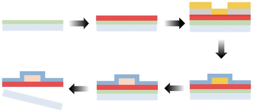
Wang et al. Microsystems & Nanoengineering (2021)7:56                                                                                                  Page 10 of 10

26. Lee, J. et al. Stretchable semiconductor technologies with high areal          30. Peppas, N. A. & Merrill, E. W. Development of semicrystalline poly(vinyl
    coverages and strain-limiting behavior: demonstration in high-                     alcohol) hydrogels for biomedical applications. J. Biomed. Mater. Res. 11,
    efficiency dual-junction GaInP/GaAs photovoltaics. Small 8,                         423–434 (1977).
    1851–1856 (2012).                                                              31. Wong, K. K. H., Zinke-Allmang, M. & Wan, W. Effect of annealing on aqueous
27. Lee, J. et al. Stretchable GaAs photovoltaics with designs that enable high        stability and elastic modulus of electrospun poly(vinyl alcohol) fibers. J. Mater.
    areal coverage. Adv. Mater. 23, 986–991 (2011).                                    Sci. 45, 2456–2465 (2010).
28. Nam, J. et al. Transfer printed flexible and stretchable thin film solar cells   32. Peppas, N. A. Infrared spectroscopy of semicrystalline poly(vinyl alcohol) net-
    using a water-soluble sacrificial layer. Adv. Energy Mater. 6, 1601269              works. Makromol. Chem. 178, 595–601 (1977).
    (2016).                                                                        33. Meng, Y., Li, Z. B., Chen, X. & Chen, J. P. A flexible dry micro-dome electrode for
29. Miyamoto, A. et al. Inflammation-free, gas-permeable, lightweight,                  ECG monitoring. Microsyst. Technol. 21, 1241–1248 (2015).
    stretchable on-skin electronics with nanomeshes. Nat. Nanotechnol. 12,         34. Huang, G, Liu, Z, Pleiss, G, Maaten, LVD & Weinberger, K Convolutional net-
    907–913 (2017).                                                                    works with dense connectivity. IEEE Trans. Pattern Anal. Mach. Intell. 1-1 (2019).
You can also read