Skeleton-based Variational Mesh Deformations
←
→
Page content transcription
If your browser does not render page correctly, please read the page content below

EUROGRAPHICS 2007 / D. Cohen-Or and P. Slavík                                                                              Volume 26 (2007), Number 3
(Guest Editors)

                     Skeleton-based Variational Mesh Deformations

                                         Shin Yoshizawa 1                Alexander Belyaev 2         Hans-Peter Seidel 2

                                                            1   RIKEN                     2   MPI Informatik

         Abstract
         In this paper, a new free-form shape deformation approach is proposed. We combine a skeleton-based mesh de-
         formation technique with discrete differential coordinates in order to create natural-looking global shape defor-
         mations. Given a triangle mesh, we first extract a skeletal mesh, a two-sided Voronoi-based approximation of the
         medial axis. Next the skeletal mesh is modified by free-form deformations. Then a desired global shape deforma-
         tion is obtained by reconstructing the shape corresponding to the deformed skeletal mesh. The reconstruction is
         based on using discrete differential coordinates. Our method preserves fine geometric details and original shape
         thickness because of using discrete differential coordinates and skeleton-based deformations. We also develop
         a new mesh evolution technique which allow us to eliminate possible global and local self-intersections of the
         deformed mesh while preserving fine geometric details. Finally, we present a multi-resolution version of our ap-
         proach in order to simplify and accelerate the deformation process. In addition, interesting links between the
         proposed free-form shape deformation technique and classical and modern results in the differential geometry of
         sphere congruences are established and discussed.
         Categories and Subject Descriptors (according to ACM CCS): I.3.5 [Computer Graphics]: Computational Geometry
         and Object Modeling

1. Introduction                                                                         two sides of the skeleton: each regular skeleton point is du-
                                                                                        plicated and each duplicate is assigned with its correspond-
Global free-form mesh deformations is an active research
                                                                                        ing radial vector.) A free-form deformation is then applied to
area which is greatly stimulated by demands of the digi-
                                                                                        the skeleton while the radial vectors and their relative posi-
tal entertainment industry. Each year brings new approaches
                                                                                        tions (w.r.t. the skeleton) are preserved. The deformed shape
as well as combinations and reworking of old favorites
                                                                                        is now reconstructed for the deformed skeleton and its ra-
[BSPG06, BPGK06, FTS06, HSL∗ 06, JSW05, LSCOL05].
                                                                                        dial vector field. Mathematical aspects of such surface re-
and this year is not an exception [BPWG07, LCOGL07,
                                                                                        construction and representation is currently a subject of in-
JMD∗ 07, KMP07] In particular, skeleton-based mesh de-
                                                                                        tensive research [GK03, Dam05, Dam07].
formation techniques remain powerful and competitive
[YBS03, DQ04, LKA06, YHM06, IBP07, WSLG07].
   In this paper, we propose a new approach to skeleton-                                   The idea of skeleton-based shape deformations was pro-
based global mesh deformations. Conceptually our approach                               posed by Blum, the inventor of the skeleton [Blu67]. (The
to free-form shape deformations is quite simple. Given a 3D                             Blum skeleton is also known under the name of Medial
solid, we extract its Blum skeleton and represent the bound-                            Axis, but we prefer to call it “skeleton” since for generic
ary of the solid as the envelope of spheres whose centers                               3D shapes it consists of a set of surface patches glued to-
lie on the skeleton. The boundary is now determined by the                              gether.) In his seminal paper [Blu73], Blum suggested to
geometry of the skeleton and a radial vector field from the                             consider the so-called flexures, shape deformations which
sphere centers to the boundary of the solid. (Each sphere                               changes the skeleton of a plane figure while maintaining
centered at a regular point of the skeleton has two points of                           the object’s width associated with the skeleton. In graph-
tangency with the envelope and, therefore, defines two radial                           ics and modeling, skeleton-based deformation techniques
vectors from the sphere center to the tangency points. In or-                           [BL99, Blo02, YBS03] appeared as natural generalizations
der to define properly the radial vector field we distinguish                           of metaballs [Bli82] and convolution surfaces [BS91]. At

 c The Eurographics Association and Blackwell Publishing 2007. Published by Blackwell
Publishing, 9600 Garsington Road, Oxford OX4 2DQ, UK and 350 Main Street, Malden,
MA 02148, USA.
S. Yoshizawa, A. Belyaev, and H.-P. Seidel / Skeleton-based Variational Mesh Deformations

                     (a)                                      (b)                            (c)                                   (d)
Figure 1: A skeleton-based variational mesh deformation example. (a): The Armadillo model represented according to the
Displaced Subdivision Surface (DSS) multi-resolution scheme [LMH00] (332K triangles), the skeletal mesh computed for the
DSS base mesh (5K triangles), and a stick-figure skeleton to be used for a deformation of the skeleton. (b): A Skeletal Subspace
Deformation (SSD) [MTLT88, LCJ94] is applied to the skeletal mesh. (c): A deformation of the DSS control mesh is obtained
by using discrete differential coordinates associated with the deformed skeletal mesh. (d): Displacement details are added to
the deformed DSS control mesh.

present skeleton-based shape manipulations are widely used                [Ale03, Sor06] in order to create natural-looking global
for biomedical image analysis purposes [PFF∗ 03].                         shape deformations. Given a triangle mesh, we first extract a
                                                                          skeletal mesh, a two-sided Voronoi-based approximation of
   Surprisingly shape deformations similar to Blum’s flex-                the skeleton (medial axis). Next the skeletal mesh is modi-
ures were considered fifty years earlier by Bianchi [Bia23,               fied by free-form deformations. Then a desired global shape
Chap. XIX] in connection with his study of families of                    deformation is obtained by reconstructing the shape corre-
spheres (sphere congruences) and their envelopes. One re-                 sponding to the deformed skeletal mesh. The reconstruc-
markable Bianchi’s result is that given a two-parameter fam-              tion is based on using discrete differential coordinates. Our
ily of spheres and its envelope, if the locus of the centers is           method preserves fine geometric details and original shape
bended the two points of contact of each sphere with the en-              thickness because of using discrete differential coordinates
velope retain invariable positions. (A simple proof of this               and skeleton-based deformations. We also develop a new
statement is given in Appendix A of our paper.) This obser-               mesh evolution technique which allow us to eliminate possi-
vation is at the heart of our approach.                                   ble global and local self-intersections of the deformed mesh
   Of course, a practical realization of the above general the-           while preserving fine geometric details. Finally, we present a
oretical strategy for skeleton-based deformations is far from             multi-resolution version of our approach in order to simplify
being simple. First of all, a robust extraction of the skele-             and accelerate the deformation process. The main stages of
ton and the radial field is a difficult problem. Second, shape            our approach are demonstrated in Fig. 1 and typical mesh
reconstruction from the deformed skeleton and the corre-                  deformations are also shown in Fig. 2.
sponding radial vector field is a tough computational task.
Next, the reconstructed shape may have (and usually has)                  2. Skeleton extraction and deforming
self-intersections and further post-processing procedures are
needed to eliminate them. Finally, straightforward imple-                 Consider a closed surface M and its skeletal structure
menting of the above approach for complex shapes approx-                  (S, R), where S is the skeleton of M and R is the cor-
imated by large-size meshes is time consuming and, there-                 responding radial function. Following [HBK02, YBS03,
fore, not practical.                                                      Dam05, Dam07] let us consider the “double” of S, the sur-
                                                                          face generated by stretching M over S by the so-called
   In our approach, we combine a skeleton-based mesh de-                  grassfire flow moving M in the direction of its inward nor-
formation technique with discrete differential coordinates                mal with unit speed (see, for example, [Dam05] for a mathe-

                                                                                            c The Eurographics Association and Blackwell Publishing 2007.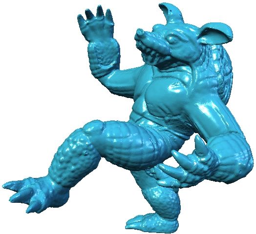
S. Yoshizawa, A. Belyaev, and H.-P. Seidel / Skeleton-based Variational Mesh Deformations

                                                       Figure 2: Gymnastic exercises for Armadillo.

matically rigorous definition of the double skeleton and nice
illustrations). Topologically the double skeleton S̃ is an or-
dinary two-sided surface homotopically equivalent to M.
Geometrically S̃ is not, in general, a smooth surface: it has
sharp edges at the singularities of the skeleton S. The one-
to-one correspondence between the points of M and S̃ can
be represented by the equation
                              M = S̃ + RN,                             (1)
where N denotes the field of outer normal of M. In the rest
of this paper, we simplify notations by denoting the double
skeleton S̃ by S.
   In geometric modeling, shape representation (1) was in-
troduced in [SPW96].
   Now we consider a discrete setting and assume that M is                      Figure 3: Skeletal mesh extraction. Left: Homer mesh and
a triangle mesh. The corresponding skeletal mesh S is gen-                      its Voronoi poles. Center: the triangulation of the Voronoi
erated as follows. First the Quickhull algorithm [BDH96] is                     poles inherits the Homer mesh connectivity. Right: the re-
used to compute the Voronoi diagram of the set of vertices                      sulting skeletal mesh.
of M and for each vertex its Voronoi cell is determined.
Then the vertices of S are computed as the inner Voronoi
poles [ABK98]. Finally the connectivity (topology) of S is
inherited from the connectivity of M. The resulting skeletal                    of S for which the inner product between the flow speed vec-
mesh S satisfies (1) where N is the set of the corresponding                    tor and the displacement vector in (1) is negative. The flow
outer mesh normals at the vertices of M.                                        mostly acts on the skeleton’s sharp edges where the density
                                                                                of the skeletal mesh vertices is high and the angle between
   It is well known that the skeleton of a shape is highly
                                                                                the flow speed and n, the outer normal of M, is obtuse. Thus
sensitive to even small perturbations of the shape. However
                                                                                the flow reduces geometric complexity of the skeleton. Fi-
we are not interested in a very accurate extraction of the
                                                                                nally, the radial function R is appropriately updated.
skeleton since inaccuracies can be compensated by the ra-
dial function R in (1). We gently simplify the geometry of                         Any intuitive free-form deformation technique for the
the skeleton by applying a variant of the bi-Laplacian tan-                     skeletal mesh seems appropriate for our approach. In partic-
gential flow [WSGD00] to the skeletal mesh. Namely, the                         ular, inspired by [MTLT88, LCJ94, Blo02] we implemented
bi-Laplacian tangential flow is applied only to those vertices                  a Skeletal Subspace Deformation (SSD) scheme. The de-

c The Eurographics Association and Blackwell Publishing 2007.
S. Yoshizawa, A. Belyaev, and H.-P. Seidel / Skeleton-based Variational Mesh Deformations
formations of the skeletal mesh are controlled by deforma-
xk sk sdk
tions of a stick-figure skeleton built manually for the skeletal
mesh, as seen in Fig. 1. v0 t 20 vd t 2d
M S Sd
3. Mesh reconstruction from deformed skeleton xi xj si t 1 sj s d
t 1d sdj
0 i
1 2 1 2
Our task now is to reconstruct a deformed mesh Md using B 0 = (v0 ,t ,t ) 0 0 B d = (vd ,t d ,t d)
the deformed skeletal mesh Sd and radial field R.
Figure 5: Corresponding triangles of M, S, and Sd . Local
First, a fragmented mesh MF (a triangle soup) is gener-
coordinate frames are attached to the corresponding trian-
ated by applying local transformations to all triangles of M
gles of S and Sd .
where the transformations are defined by according to the
local frames attached S and Sd . Then Md is obtained by
stitching the fragmented mesh triangles based on minimiz-
ing and redistributing a deformation error. Here the error is the local coordinate transform Bd B−1
0 defined for each tri-
given by a squared difference between the discrete differ-
angle T of Sd is used to approximate ndi :
ential coordinates of MF and Md . Similar strategies were
applied for stitching fragmented meshes in [SP04, YZX∗ 04,
.
ndi = Bd B−1
0 (xi − si ) Bd B−1
0 (xi − si ) .
ZRKS05].
The vertices of fragmented mesh MF are given by
Let x, s, and sd be the corresponding vertices of meshes
M, S, and Sd , respectively. According to (1) the corre- xFi = sdi + Ri ndi . (3)
sponding vertex of the deformed mesh Md should computed
by
xd = sd + R nd , (2) Fragmented Mesh M F
where R = |x − s| is the radius of the medial ball of M cen- stitching
tered at s, as seen in Fig. 4. In practice, instead of (2) a sim- xFi
xFj
ilar shift transformation is applied to the triangles of the de- x di
formed skeletal mesh Sd . vd x F
k
sdi t 1d
n n d t Deformed Mesh M d
2
Md d
xi x d
i
Deformed Skeletal Mesh S d
M
R R Sd
S d
s Figure 6: Skeleton-based variational mesh deformation
i
si framework. First fragmented mesh (triangle soup) MF is
generated from deformed skeletal mesh Sd . Then differential
coordinates are used for stitching the triangles of MF .
Figure 4: Left: a given shape is represented as an envelope
of spheres centered at the skeleton of the shape. Deform-
ing the skeleton while preserving the sphere radii implies a Our task now is to reconstruct a deformed mesh Md
global shape deformation. from fragmented mesh MF , as seen in Fig. 6. One possi-
ble solution [KO03] consists of generating vertex positions
xdi ∈ Md via simple averaging the positions of the corre-
Let {xi , x j , xk }, {si , s j , sk }, and {sdi , sdj , sdk } be corre- sponding vertices of the the fragmented mesh MF . While
sponding
triangles of M, S, and Sd , respectively. Denote by this approach seems attractive because of its simplicity, bet-
1 2 ter reconstruction results are usually achieved when differ-
B0 = v0 , t0 , t0 a basis-vector frame defined by the skeletal
mesh triangle {si , s j , sk }. Here ential mesh coordinates are employed for the reconstruc-
tion [YZX∗ 04, ZRKS05, ZHS∗ 05]. Further, the use of dif-
s j − si sk − si ferential coordinates allows us to easily take into account
t10 = , t20 = , and v0 = t10 × t20 .
|s j − si | |sk − si | the influence of the deformed skeletal mesh Sd .
The corresponding basis-vector frame for {sdi , sdj , sdk } is Consider the graphs G and GF composed from the pairs
computed similarly. See Fig. 5 for an illustration. of meshes {M, S} and {MF , Sd }, respectively. The con-
nectivity structures of G and GF are shown in Fig. 7.
It is accurate and computationally robust to approximate
the normal ni of M at xi by (xi − si )/|xi − si | [DS06]. Now Let us equip the edges of G and GF with weights. Each
c The Eurographics Association and Blackwell Publishing 2007.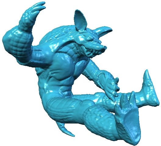
S. Yoshizawa, A. Belyaev, and H.-P. Seidel / Skeleton-based Variational Mesh Deformations

                                                         s di        s dj              ally expensive optimization stage). The skeletal mesh is ex-
             si           sj
                                                                                       tracted from the coarse DSS control mesh. Then the con-
                                                                                       trol mesh is deformed as described above. Finally, fine shape
                                                                                       features are reconstructed by subdividing the deformed con-
                                                                            MF
                   αij          M                                                      trol mesh and adding displacements along the normals of the
         xi β ij           xj                       xT                                 subdivided deformed mesh.
                                                                                          In Fig. 8, we demonstrate advantages of using DSS. In ad-
                                                                                       dition to a great acceleration of the deformation process, the
            Figure 7: Graphs G (left) and GF (right).
                                                                                       DSS control mesh has a much simple skeleton which pro-
                                                                                       vides the user with a better control for global shape defor-
                                                                                       mations.
edge (xi , x j ) of G is assigned with the standard cotan weight
w(xi , x j ) = cot αi j + cot βi j [PP99] where αi j and βi j are the
angles opposite to (xi , x j ) in M, as seen in the left image
of Fig. 7. The edges connecting (xi , si ) are assigned with
the unit weights w(xi , si ) = 1. For a triangle (xFi xFk xFj ) of
GF , the triangle edge (xFi , xFj ) is equipped with the weight
w f (xFi , xFj ) = cot ∠xi xk x j where the angle is measured in
M. The edges connecting (xFi , sdi ) are assigned with weights
w(xFi , sdi ) = 1/Ni , where Ni is the number of the one-link
neighborhood triangles of xi in M.
   Once G and GF become weighted graphs, the graph-
Laplacians of G and GF are appropriately defined [Chu97].                                     Dense mesh and its corresponding skeletal mesh
Let L be the Laplacian matrix of M. Then the list of ver-
tices xd = {xdi } of the deformed mesh Md is determined
from xF = {xFi } and sd = {sdi } by solving
       d                       d
        x           I + L −I          x       y
    L d ≡                                   =      , (4)
        s             0       I       sd      sd
where the list of vertices y = {yi } is generated from the ver-
tices of GF by
                                                                 xFi − sdi
       yi =    ∑ w1 (xFi − xFj ) + w2 (xFi − xFk ) +                 Ni
                                                                           .
              ( j,k)
                                                                                         DSS control mesh and its skeletal mesh (5.2K triangles)
Here the sum is taken over the set of index pairs ( j, k) cor-
responding to the edges of M opposite to vertex xi ∈ M,                                         Number of    Editing     Updating
                                                                                                                                     DSS       Total
w1 = cot ∠xi xk x j , w2 = cot ∠xi x j xk .                                                     Triangles    Skeleton    Geometry
                                                                                                  346K         94 s       1023 s              1117 s
   Notice that y can be considered as the result of applying
                                                                                        DSS     5.2+332K      0.13 s       0.3 s      3.8 s   4.23 s
the graph-Laplacian of GF to the vertices of MF .
                                                                                       Figure 8: Adding a multi-resolution mesh representation
  One can easily see that the vertices xd obtained from (4)
                                                                                       (we use a simplified version of DSS of [LMH00]) greatly
depend only on xF , the vertices of the fragmented MF , and
                                                                                       accelerates the deformation process and simplifies the user
can be determined by solving a simpler sparse linear system
                                                                                       control. The table presents timing measurements corre-
                                                                        xFi            sponding to the mesh deformation shown in Fig. 1.
(I + L) xd = ỹ, ỹi = ∑w1 (xFi −xFj )+w2 (xFi −xFk )+                      .    (5)
                                                                        Ni
However, as we will see later, the operator L in (4) turns out
to be very useful for removing possible self-intersections of
                                                                                       4. Removing mesh self-intersections
Md .
                                                                                       The deformed mesh Md approximates the envelope of
Multi-resolution representation. In order to process large-                            spheres centered at Sd and may contain self-intersections, as
size models and accelerate our mesh deformation tech-                                  seen in the left image of Fig. 9. A natural way to avoid such
nique we have implemented a Displaced Subdivision Sur-                                 self-intersections is to consider the boundary of the boolean
face (DSS) approach of [LMH00] (without its computation-                               union of the balls bounded by the spheres, as seen in the

 c The Eurographics Association and Blackwell Publishing 2007.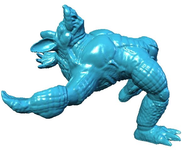
S. Yoshizawa, A. Belyaev, and H.-P. Seidel / Skeleton-based Variational Mesh Deformations

right image of Fig. 9. The boolean union can be described
by a function

       f (z) = min z ∈ R3 : |z − sdi | − Ri , sdi ∈ Sd
                  n                                    o
                                                         (6)
                i

and the boundary of the union is given by the equation
                             f (z) = 0.                         (7)
Therefore it seems natural to resolve self-intersections of               Figure 10: Preconditioning with L−1 in (9) allows us to
Md by moving its vertices towards (7).                                    avoid defects similar to that shown in the left image. Such
                                                                          defects appear because of a discrete nature of our approxi-
                                                                          mation to the envelope of spheres. Skeletal mesh Sd serves
                                                                          as an anchor in (9) and a correct approximation of the enve-
                                                                          lope is achieved, as seen in the right image.

                                                                             The power of our approach to resolve mesh self-
                                                                          intersections is demonstrated in Fig. 11. Note that mesh evo-
                                                                          lution (9) improves the accuracy of the deformed mesh by
                                                                          pushing it towards the boundary of the union of the medial
                                                                          balls (an example of such a union is shown in the right image
                                                                          of Fig. 9).
Figure 9: Envelope vs. Union. Left: the envelope of a family
of spheres. Right: the boundary of the union of the corre-
sponding balls.

   Consider the graph G(t) composed from the vertices x =
{xi } and sd = {sdi } of moving mesh M(t) and the deformed
skeleton Sd , respectively. In order to move M(t) towards
(7) we use the antigradient of 12 f 2 and evolve the graph by
                                                                          Figure 11: Global self-intersection fairing. Left: a deformed
                             − f (z)∇ f (z) if z = xd

  ∂[L G(t)]
             = F (G(t)) ≡                                   (8)           mesh contains self-intersections. Right: evolution (9) effi-
      ∂t                        0             if z = sd                   ciently removes the self-intersections.
where the evolution starts from the deformed mesh and its
skeleton G(0) = (Md , Sd ) and L is defined in (5) and re-                   A straightforward computation of (6) and, therefore, the
mains constant during (8). Note that the skeletal mesh Sd is              right-hand side of (9) is time-consuming. In order to accel-
also not affected by (8) but serves as an anchor for M(t).                erate discrete evolution (9) we simplify (6) by considering a
                                                                          proper subset of the medial balls centered at the vertices of
  To solve (8) numerically we consider the following semi-                Sd .
implicit scheme
                                                                             Let us observe that for each vertex ui = {xi , sdi } of G(t)
                    n+1      n      −1      n
                u         = u +τL        F(u ),                 (9)       the value f (xi ) is bounded by |xi − sdi | − Ri . Thus it is nat-
where u0 = (xd , sd ) and τ is a step-size parameter. The ma-             ural to approximate the antigradient of 12 f 2 at xi by
trix L−1 is already computed† when (4) was solved and re-
mains the same during the above graph evolution (9).                            − f (xi )∇ f (xi ) ≈ |xi − sdp | − R p xi − sdp ,
                                                                                                        n                  o
   Resolving mesh self-intersections by applying an ap-                                   p = argmin j |xi − sdj | − R j |                         (10)
propriately defined mesh evolution was previously used in
[YBS03]. Our mesh evolution scheme (9) is simpler than                    and the minimum is taken over all u j = (x j , sdj ) such that
that employed in [YBS03]. In addition, (9) treats the vertices            |x j − xi | ≤ Ri . For fast evaluating (10) a kd-tree search struc-
of the skeletal mesh Sd as anchors and prevents developing                ture is constructed and updated after each iteration of (9).
defects similar to that shown in the left image of Fig. 10.                  If a model has a complex geometry (e.g., a deformed Ar-
                                                                          madillo mesh), flow (9) is applied to the DSS control mesh
                                                                          of the model. For a simple model, like the ellipsoid from
† Sparse direct solver [Dav04] is employed to compute L−1 .               Fig. 9), the flow is applied to the model itself.

                                                                                            c The Eurographics Association and Blackwell Publishing 2007.
S. Yoshizawa, A. Belyaev, and H.-P. Seidel / Skeleton-based Variational Mesh Deformations

                                                                                         (a)                    (b)               (c)

Figure 12: A comparison of SSD [MTLT88,LCJ94] and our
skeleton-based variational approaches. Left: original shape
(an ellipsoid). Center: SSD is applied. Right: our method is
used.

  Of course, if (9) is applied to the DSS control mesh of
a model, one cannot guarantee that all intersections of the                              (d)                    (e)               (f)
model will be removed by (9).
                                                                               Figure 13: A comparison of several popular schemes for
   According to our numerical experiments, typically 10-                       computing a deformed shape from a deformed skeleton.
50 iterations of (9) are needed to remove self-intersections                   For each deformed mesh, the computational time is given
and improve the mesh quality. Our implementation of (9) is                     in seconds and surface approximation error ε is measured
reasonably fast. For example, it takes only 0.16s per itera-                   by summing up the values of (6) computed at the vertices
tion for the ellipsoid mesh from Fig. 12 (4.9K triangles) and                  of the deformed mesh. (a): Ellipsoid and its skeletal mesh
0.12s per iteration of the DSS control mesh of the Armadillo                   (19.6K triangles). (b): Deformed skeletal mesh. (c): SSD
model. ‡                                                                       method [MTLT88, LCJ94], 2.3s, ε = 20.2. (d): Homotopy
                                                                               method [YBS03] (no DSS acceleration), 2.7s, ε = 19.6. (e):
5. Discussion                                                                  Weighted blending [Blo02], 14.8s, ε = 11.8. (f): The method
                                                                               of this paper (no DSS acceleration) 2.9s, ε = 3.8. Evolution
The two main advantages of our mesh deformation method                         (9) decreases the approximation error: ε = 0.2.
are preserving the thickness of the deformed models and
an elegant geometric way for removing possible mesh self-
intersections. To the best of our knowledge, the latter is-
sue is very rarely addressed in the shape deformation liter-                   thicknesses of a deformed model is a desirable feature which
ature. Both the advantages are natural consequences of the                     can provide the user with a simple and intuitive control over
skeleton-based shape representation in which a given sur-                      the deformation process.
face is represented as the envelope of spheres centered at the
skeleton of the figure bounded by the surface.                                    To compare with previous skeleton-based shape deforma-
                                                                               tion methods, we believe that our approach provides the
  In Fig. 12, we use a simple shape (an ellipsoid) to compare                  user with a richer set of deformations than line-skeleton
with the SSD technique [MTLT88, LCJ94], an axial-based                         techniques [LKA06, YHM06] and delivers a better preser-
shape deformation approach. In Fig. 13, the same model is                      vation of shape features under larger-scale deformations
used for a comparison of various techniques for shape re-                      than other schemes based on the classical Blum skeleton
construction from a deformed skeleton.                                         [YBS03, DQ04]. See, for example, Fig. 13 for a comparison
   Thickness preservation, an intrinsic property of our ap-                    of our approach with that developed in [YBS03].
proach, is missed by most of the modern non-skeletal shape                        While PriMo [BPGK06], rigid cells [BPWG07], and Vol-
deformation techniques (as far as we can judge, only the                       umetric Graph Laplacian [ZHS∗ 05] techniques are capable
rigid cell approach proposed [BPWG07] is capable to pre-                       of avoiding local self-intersections, only vector field based
serve thicknesses of deformed models). Several methods de-                     approaches [ACWK06, FTS06], and another skeleton-based
liver volume-preserving deformations [ZHS∗ 05,FTS06]. We                       deformation method [YBS03] are our competitors in the
think, however, that for many applications preserving the                      ability to avoid global mesh self-intersections. To compare
                                                                               with [YBS03] our self-intersection fairing flow (8), (9) is
‡ All the computations described in this paper were performed on
                                                                               very fast.
a 1.7GHz Pentium 4 with 1GB RAM.                                                  Of course our method is not free from drawbacks. Some

c The Eurographics Association and Blackwell Publishing 2007.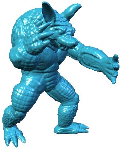
S. Yoshizawa, A. Belyaev, and H.-P. Seidel / Skeleton-based Variational Mesh Deformations

deformation defects can be observed on the left leg of the             Acknowledgements
Homer model and the neck of the Stanford Dragon. (For the
                                                                       We would like to thank the anonymous reviewers of this pa-
Homer model, they are especially visible because the mesh
                                                                       per for their helpful comments and suggestions.
does not contain high-frequency details which usually pro-
duce a masking effect.) The problem here is that the skeleton            The models are courtesy of Stanford University (Ar-
of a canal surface degenerates into a space curve. In practice,        madillo and Dragon) and INRIA Sophia-Antpolis (Homer).
the skeletal mesh of a model close to a canal surface is of a
                                                                         This work was supported in part by AIM@SHAPE, a
poor quality and certain instabilities may appear during our
                                                                       Network of Excellence project (506766) within EU’s Sixth
mesh reconstruction process.
                                                                       Framework Programme, and Strategic Programs for R&D
                                                                       (President’s Discretionary Fund) of RIKEN.

                                                                       References
                                                                       [ABK98] A MENTA N., B ERN M., K AMVYSSELIS M.: A
                                                                         new Voronoi-based surface reconstruction algorithm. In
                                                                         Proceedings of ACM SIGGRAPH (1998), pp. 415–421.
                                                                       [ACWK06] A NGELIDIS A., C ANI M.-P., W YVILL G.,
                                                                         K ING S.: Swirling-sweepers: constant volume modeling.
                                                                         Graphical Models (GMOD) 68, 4 (2006). Special issue
                                                                         on PG’04.
                                                                       [Ale03] A LEXA M.: Differential coordinates for local
                                                                         mesh morphing and deformation. The Visual Computer
                                                                         19, 2-3 (2003), 105–114.
                                                                       [BDH96] BARBER C. B., D OBKIN D. P., H UHDANPAA
                                                                         H. T.: The Quickhull algorithm for convex hulls. ACM
                                                                         Transactions on Mathematical Software 22, 4 (1996),
                                                                         469–483.
                                                                       [Bia23] B IANCHI L.: Lezioni di Geometria Differenziale
                                                                         (Volume II, Parte prima). Enrico Spoerri, Pisa, 1923.
                                                                       [BL99] B LOOMENTHAL J., L IM C.: Skeletal methods
Figure 14: More deformation examples. Certain defects can                of shape manipulation. In International Conference
be observed on the left leg of the Homer model and the neck              on Shape Modeling and Applications (SMI’99) (1999),
of the Stanford Dragon.                                                  pp. 44–47.
                                                                       [Bli82] B LINN J. F.: A generalization of algebraic sur-
   Our approach would be greatly enhanced if we were given               face drawing. ACM Transactions on Graphics 1, 3 (1982),
a method for generating bending deformations (i.e., preserv-             235–256.
ing the first fundamental form) of the skeletal mesh. Then,
                                                                       [Blo02] B LOOMENTHAL J.: Medial-based vertex defor-
as shown in Appendix A, the first fundamental form of M
                                                                         mation. In ACM SIGGRAPH / Eurographics Symposium
(and, therefore, the surface area element) is also preserved
                                                                         on Computer Animation (SCA ’02) (2002), pp. 147–151.
in the deformation process. In addition, several global char-
acteristics of a figure bounded by M are bending invariants            [Blu67] B LUM H.: A transformation for extracting new
of the skeleton S of the solid [Dam07, Nád68]. While pro-                descriptors of shape. In Symposium on Models for the
ducing pure bending deformations of a surface seems a diffi-             Perception of Speech and Visual Form (1967), Wathen-
cult nonlinear problem, its approximate solution in the case             Dunn W., (Ed.), MIT Press, pp. 362–380.
of the skeleton does not look very hard. Everyone who deal             [Blu73] B LUM H.: Biological shape and visual science
with skeletons should observe that S in its regular points               (part i). J. of Theoretical Biology 38 (1973), 205–287.
is much less curved than M in the corresponding points.
Roughly speaking, the deformation retract M → S converts               [BPGK06] B OTSCH M., PAULY M., G ROSS M.,
highly curved regions of M into singularities of S. Although             K OBBELT L.: PriMo: coupled prisms for intuitive surface
so far this observation is supported by rigorous mathemat-               modeling.    In 4th Eurographics / ACM SIGGRAPH
ical statements in 2D case only (see Appendix B), results                Symposium on Geometry Processing (SGP’06) (2006),
of [SSR99] suggest that the observation is mathematically                pp. 11–20.
valid in 3D as well.                                                   [BPWG07]        B OTSCH M., PAULY M., W ICKE M., G ROSS

                                                                                         c The Eurographics Association and Blackwell Publishing 2007.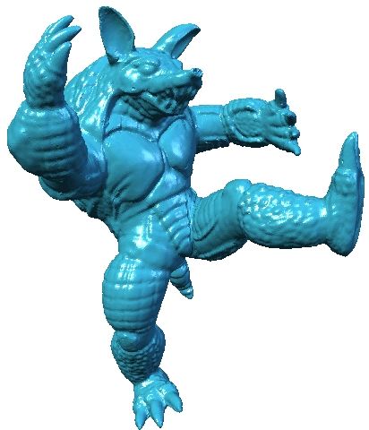
S. Yoshizawa, A. Belyaev, and H.-P. Seidel / Skeleton-based Variational Mesh Deformations

  M.: Adaptive space deformations based on rigid cells.                           B., S ANOCKI T.: Harmonic coordinates for character ar-
  Computer Graphics Forum 26, 3 (2007). Proc. Euro-                               ticulation. ACM Transactions on Graphics 26, 3 (2007).
  graphics 2007.                                                                  Proc. ACM SIGGRAPH 2007.
[BS91] B LOOMENTHAL J., S HOEMAKE K.: Convolution                              [JSW05] J U T., S CHAEFER S., WARREN J.: Mean value
  surfaces. In Proceedings of AMS SIGGRAPH ’91 (1991),                            coordinates for closed triangular meshes. ACM Transac-
  pp. 251–256.                                                                    tions on Graphics 24, 3 (2005), 561–566. Proc. ACM
[BSPG06] B OTSCH M., S UMNER R., PAULY M., G ROSS                                 SIGGRAPH 2005.
  M.: Deformation transfer for detail-preserving surface                       [KMP07] K ILIAN M., M ITRA N. J., P OTTMANN H.: Ge-
  editing. In Vision, Modeling & Visualization (Aachen,                          ometric modeling in shape space. ACM Transactions on
  Germany, November 2006), pp. 357–364.                                          Graphics 26, 3 (2007). Proc. ACM SIGGRAPH 2007.
[Chu97] C HUNG F. R. K.: Spectral Graph Theory. Amer-                          [KO03] K OBAYASHI K. G., O OTSUBO K.: t-FFD: Free-
  ican Mathematical Society, 1997. CBMS, Regional Con-                           form deformation by using triangular mesh. In Eight ACM
  ference Series in Mathematics, Number 92.                                      Symposium on Solid Modeling and Applications (2003),
                                                                                 pp. 226–234.
[Dam05] DAMON J. N.: Determining the geometry of
  boundaries of objects from medial data. International                        [LCJ94] L AZARUS F., C OQUILLART S., JANCÉNE P.:
  Journal of Computer Vision 63, 1 (2005), 45–64.                                Axial deformations: an intuitive deformation technique.
                                                                                 Computer-Aided Design 26, 8 (1994), 607–613.
[Dam07] DAMON J. N.: Global geometry of regions and
  boundaries via skeletal and medial integrals. Communi-                       [LCOGL07] L IPMAN Y., C OHEN -O R D., G AL R.,
  cations in Analysis and Geometry (2007).                                       L EVIN D.: Volume and shape preservation via moving
                                                                                 frame manipulation. ACM Transactions on Graphics 26,
[Dav04] DAVIS T. A.: UMFPACK - an unsymmetric-                                   1 (January 2007).
  pattern multifrontal method with a column pre-ordering
  strategy. ACM Transactions on Mathematical Software                          [LKA06] L IEN J.-M., K EYSER J., A MATO N. M.: Si-
  30, 2 (2004), 196–199.                                                         multaneous shape decomposition and skeletonization. In
                                                                                 ACM Solid and Physical Modeling Symposium (SPM’06)
[DQ04] D U H., Q IN H.: Medial axis extraction and shape                         (2006), pp. 219–228.
  manipulation of solid objects using parabolic PDEs. In
  Ninth ACM symposium on Solid Modeling and Applica-                           [LMH00] L EE A., M ORETON H., H OPPE H.: Displaced
  tions (SM’04) (2004), pp. 25–35.                                               subdivision surfaces. In Proceedings of ACM SIGGRAPH
                                                                                 (2000), pp. 85–94.
[DS06] D EY T. K., S UN J.: Normal and feature approxi-
  mations from noisy point clouds. In FSTTCS 2006: Foun-                       [LSCOL05] L IPMAN Y., S ORKINE O., C OHEN -O R D.,
  dations of Software Technology and Theoretical Com-                            L EVIN D.: Linear rotation-invariant coordinates for
  puter Science. LNCS 4337 (2006), pp. 21–32.                                    meshes. ACM Transactions on Graphics 24, 3 (2005).
                                                                                 Proc. ACM SIGGRAPH 2005.
[FTS06] F UNCK W. V., T HEISEL H., S EIDEL H.-P.:
                                                                               [MTLT88] M AGNENAT-T HALMANN N., L APERRIÉRE
  Vector-field-based shape deformations. ACM Transac-
                                                                                 R., T HALMANN D.: Joint-dependent local deformations
  tions on Graphics 25, 3 (2006), 1118–1125. Proc. ACM
                                                                                 for hand animation and object grasping. In Graphics In-
  SIGGRAPH 2006.
                                                                                 terface ’88 (1988), pp. 26–23.
[GK03] G IBLIN P. J., K IMIA B. B.: On the intrinsic re-
                                                                               [Nád68] N ÁDENÍK Z.: Zur geometrie im grossen der
  construction of shape from its symmetries. IEEE Trans.
                                                                                 kugelkongruenzen. Czechoslovak Math. J. 18 (93) (1968),
  Pattern Anal. Mach. Intell. 25, 7 (2003), 895–911.
                                                                                 700–717.
[HBK02] H ISADA M., B ELYAEV A. G., K UNII T. L.:
                                                                               [PFF∗ 03] P IZER S. M., F LETCHER T., F RIDMAN Y.,
  A skeleton-based approach for detection of perceptually
                                                                                 F RITSCH D. S., G ASH A. G., G LOTZER J. M.,
  salient features on polygonal surfaces. Computer Graph-
                                                                                 J OSHI S., T HALL A., T RACTON G., Y USHKEVICH P.,
  ics Forum 21, 4 (2002), 1–12.
                                                                                 C HANEY E. L.: Deformable M-reps for 3D medical im-
[HSL∗ 06] H UANG J., S HI X., L IU X., Z HOU K., W EI                            age segmentation. International Journal of Computer Vi-
  L., T ENG S., BAO H., G UO B., S HUM H.-Y.: Subspace                           sion 55, 2 (2003), 85–106.
  gradient domain mesh deformation. ACM Transactions on                        [PP99] P INKALL U., P OLTHIER K.: Computing discrete
  Graphics 25, 3 (2006), 1126–1134. Proceedings of ACM                           minimal surfaces and their conjugates. Experimental
  SIGGRAPH.                                                                      Mathematics 2, 1 (1999), 15–36.
[IBP07] I LYA BARAN I., P OPOVI Ć J.: Automatic rigging                       [Sie99] S IERSMA D.: Properties of conflict sets in the
   and animation of 3D characters. ACM Transactions on                           plane. In Geometry and Topology of Caustics – Caus-
   Graphics 26, 3 (2007). Proc. ACM SIGGRAPH 2007.                               tics ’98 (1999), Banach Center Publ. 50, Polish Acad. Sci-
[JMD∗ 07]        J OSHI P., M EYER M., D E ROSE T., G REEN                       ences, Warsaw, pp. 267–276.

c The Eurographics Association and Blackwell Publishing 2007.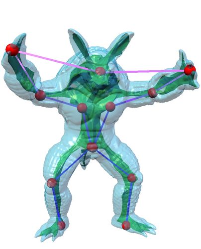
S. Yoshizawa, A. Belyaev, and H.-P. Seidel / Skeleton-based Variational Mesh Deformations

[Sor06] S ORKINE O.: Differential representations for                 where n(u, v) is the outer (w.r.t the surface of centers) unit
  mesh processing. Computer Graphics Forum 25, 4                      normal of the envelope. See Fig. 4 for an illustration. Basis
  (2006), 789–807.                                                    vectors
[SP04] S UMNER R. W., P OPOVI Ć J.: Deformation trans-                   xu = su + Ru n + Rnu          and      xv = sv + Rv n + Rnv           (11)
  fer for triangle meshes. ACM Transactions on Graphics
                                                                      are orthogonal to n. Thus, taking the scalar product of (11)
  23, 3 (2004), 399–405. Proc. ACM SIGGRAPH 2004.
                                                                      and n, we arrive at
[SPW96] S HERBROOKE C. E., PATRIKALAKIS N. M.,
  W OLTER F.-E.: Differential and topological properties                             su · n = −Ru         and        sv · n = −Rv .             (12)
  of medial axis transforms. Graphical Model and Image                Denote by m the orientation normal of the surface of centers
  Processing 58, 6 (1996), 574–592.                                   s(u, v). We have
[SSR99] S OTOMAYOR J., S IERSMA D., R. G.: Curva-                                      n = α su /|su | + β sv /|sv | + γ m                      (13)
  tures of conflict surfaces in Euclidean 3-space. In Ge-
  ometry and Topology of Caustics – Caustics ’98 (1999),              where the direction-cosines α and β are obviously obtained
  Banach Center Publ. 50, Polish Acad. Sciences, Warsaw,              from (12). The remaining direction-cosine γ is easily com-
  pp. 277–285.                                                        puted from (13). Thus the direction-cosines of n depend on
                                                                      the coefficients of the first fundamental form ds2 of the sur-
[WSGD00] W OOD Z. J., S CHRÖDER P., G REEN D.,                        face of centers s(u, v) and first-order derivatives of the radius
  D ESBRUN M.: Semi-regular mesh extraction from vol-                 function R(u, v) along the parametric curves. In particular it
  umes. In IEEE Visualization 2000 (2000), pp. 275–282.               means that, for each sphere of the family, the point of contact
[WSLG07] W EBER O., S ORKINE O., L IPMAN Y.,                          between the sphere and envelope depends on ds2 and Ru , Rv
  G OTSMAN C.: Context-aware skeletal shape deforma-                  only. Further, the area element of the envelope
  tion. Computer Graphics Forum 26, 3 (2007). Proc. Eu-
                                                                                   (su + Ru n + Rnu ) × (sv + Rv n + Rnv )
  rographics 2007.
                                                                      also depends on ds2 and derivatives of R(u, v) along the para-
[YBS03] YOSHIZAWA S., B ELYAEV A., S EIDEL H.-P.:
                                                                      metric curves of s(u, v).
  Free-form skeleton-driven mesh deformations. In 8th
  ACM Symposium on Solid Modeling and Applications
  (2003), pp. 247–253.                                                Appendix B. Curvature of the skeleton in 2D
[YHM06] YAN H.-B., H U S.-M., M ARTIN R. R.:                          Let C be a closed curve oriented by its outer unit normal n
  Skeleton-based shape deformation using simplex trans-               and S be the skeleton (medial axis) of the figure bounded
  formations. In 24th Computer Graphics Int. Conf. (CGI               by C. Consider the negative offsets of C: Cλ = C − λ n. It
  2006). LNCS 4035 (2006), pp. 66–77.                                 is well-known that skeleton S is generated by the first self-
                                                                      intersections of Cλ . Consider a non-singular point p ∈ S gen-
[YZX∗ 04] Y U Y., Z HOU K., X U D., S HI X., BAO H.,
                                                                      erated as a self-intersection of Cλ for a certain value of offset
  G UO B., S HUM H.-Y.: Mesh editing with Poisson-based
                                                                      parameter λ and denote by ϕ the angle between one of the
  gradient field manipulation. ACM Transactions on Graph-
                                                                      tangents of Cλ and the tangent of S at p. Direct computa-
  ics 23, 3 (2004), 641–648. Proc. ACM SIGGRAPH 2004.
                                                                      tions [Sie99] show that the curvature κ of S at p is given by
[ZHS∗ 05] Z HOU K., H UANG J., S NYDER J., L IU X.,
  BAO H., G UO B., S HUM H.-Y.: Large mesh deforma-
                                                                                         1

                                                                                                    k1      k2
  tion using the volumetric graph Laplacian. ACM Trans-                             κ=                  −                      cos ϕ,           (14)
                                                                                         2       1 − λk1 1 − λk2
  actions on Graphics 24, 3 (2005), 496–503. Proc. ACM
  SIGGRAPH 2005.                                                      where k1 and k2 are the curvatures of C computed at the
                                                                      points q1 and q2 corresponding to p, respectively. Equation
[ZRKS05] Z AYER R., R ÖSSL C., K ARNI Z., S EIDEL H.-
                                                                      (14) implies that
  P.: Harmonic guidance for surface deformation. Com-
  puter Graphics Forum 24, 3 (2005), 601–609.                                              2κ ds = k1 ds1 − k2 ds2 ,                            (15)
                                                                      where ds1 and ds2 are the oriented length elements of C at
Appendix A. Simple geometry of sphere envelopes                       q1 and q2 , respectively, and ds is the oriented length element
                                                                      of S at p.
Consider a smooth two-parameter family of spheres, a con-
gruence of spheres, in 3D. Let the surface of sphere centers             Denote by S ′ a set of smooth curve segments obtained
be given in a parametric form s = s(u, v) and R = R(u, v) be          from the double skeleton S̃ by removing its singular points.
the radius function. Consider an envelope M of the sphere             From (15) it follows that
congruence [s, R]. The envelope allows for a natural param-
                                                                                             Z                   Z
                                                                                                      |κ| ds ≤        |k| ds
eterization                                                                                      S′              C
             x(u, v) = s(u, v) + R(u, v)n(u, v),                      which means that S ′ is less curved than C.

                                                                                         c The Eurographics Association and Blackwell Publishing 2007.
You can also read


