Robot Vacuum ECE 445 PROJECT PROPOSAL
←
→
Page content transcription
If your browser does not render page correctly, please read the page content below
ECE 445
S ENIOR D ESIGN L ABORATORY
  P ROJECT P ROPOSAL

 Robot Vacuum

          Team #9
        T IANYU Z HANG
    (tianyu7@illinois.edu)
         L ONG C HANG
     (longc2@illinois.edu)
          Z HEYI H ANG
   (zheyih2@illinois.edu)
          K AILONG J IN
   (kailong3@illinois.edu)

      TA: Tielong Cai

       March 8, 2023
Abstract
Household robot vacuums have provided human convenience by automating floor clean-
ing work. However, the functionality of robot vacuum is not perfect and problems can
happen in its daily usage. In a big house with multiple floors, it will be sad to see the
robot falling from high places. Sometimes, the robot may be confused by the small obsta-
cles on the floor, causing it to get stuck or have an inefficient path to clean the room. So
we plan to propose a robot vacuum that can avoid such problems. By adding anti-falling
wheels and a suspension system, our robot can prevent falling from high platforms and
can cross low objects on the floor. We will also improve its path-finding algorithm by tak-
ing its ability to pass obstacles into consideration. Furthermore, we will allow the robot
to interact with a lift to make it possible for multi-floor cleaning.
iiContents
1 Introduction 1
1.1 Problem . . . . . . . . . . . . . . . . . . . . . . . . . . . . . . . . . . . . . . . 1
1.2 Solution . . . . . . . . . . . . . . . . . . . . . . . . . . . . . . . . . . . . . . . 1
1.3 High-Level Requirements List . . . . . . . . . . . . . . . . . . . . . . . . . . . 1
1.4 Visual Aid . . . . . . . . . . . . . . . . . . . . . . . . . . . . . . . . . . . . . . 2
2 Design 3
2.1 Block Diagram . . . . . . . . . . . . . . . . . . . . . . . . . . . . . . . . . . . . 3
2.2 Subsystem Overview . . . . . . . . . . . . . . . . . . . . . . . . . . . . . . . . 4
2.3 Subsystem Requirements . . . . . . . . . . . . . . . . . . . . . . . . . . . . . . 6
2.3.1 Subsystem. Anti-fall Steering . . . . . . . . . . . . . . . . . . . . . . . 6
2.3.2 Subsystem. Low Obstacles Passing . . . . . . . . . . . . . . . . . . . . 6
2.3.3 Subsystem. Elevator Interaction . . . . . . . . . . . . . . . . . . . . . 7
2.3.4 Subsystem. Effective Path-Finding . . . . . . . . . . . . . . . . . . . . 8
2.3.5 Peripheral. Driving . . . . . . . . . . . . . . . . . . . . . . . . . . . . . 9
2.3.6 Peripheral. Cleaning . . . . . . . . . . . . . . . . . . . . . . . . . . . . 10
2.4 Tolerance Analysis . . . . . . . . . . . . . . . . . . . . . . . . . . . . . . . . . 11
3 Ethics and Safety 12
3.1 Ethics . . . . . . . . . . . . . . . . . . . . . . . . . . . . . . . . . . . . . . . . . 12
3.2 Safety . . . . . . . . . . . . . . . . . . . . . . . . . . . . . . . . . . . . . . . . . 12
References 14
iii1 Introduction
1.1 Problem
As technology evolves and price decreases, robot vacuums are becoming more and more
popular. At the same time, they gradually evolved from having only a single sweeping
function to having a certain level of intelligence, including identifying room type, video
monitoring pet activities, and even family calls. However, from our daily experience in
the use of robot vacuums, there still exist many problems. One is that the robot vac-
uum may fall from a high plane without notice and break. The other is that it may get
stuck when passing through rough and uneven ground. Also, it cannot realize cross-floor
cleaning. The last problem is that the path-finding algorithm can still be improved. To
further reduce the work that workers need to do personally and increase the reliability of
the robot vacuum, the four problems above are urgent to be solved.
1.2 Solution
We propose an advanced version of the robot vacuum that can tackle these four problems.
Specifically, we design four separate subsystems and then integrate them into the existing
robot vacuum. First, the anti-fall steering system will automatically steer the robot when
it approaches the edge of the stairs by adding a mechanical structure to the bottom of the
vacuum. Second, the suspension structure will be improved to give the robot vacuum
better pass ability. To be specific, the chassis of the vacuum will automatically get raised
when the infrared sensors notice low obstacles approaching. This is our second subsys-
tem named the low obstacle passing subsystem. Third, the elevator interaction subsystem
allows the robot vacuum to call the elevator to send itself to the next floor by realizing
signal transmission between the two. In this way, it can perform multi-floor sweeping
operations. In addition, we will optimize the 2D/3D vision of today’s robot vacuum and
optimize the path-finding algorithm to further improve its efficiency and power. These
may constitute the fourth subsystem called the effective path-finding subsystem.
1.3 High-Level Requirements List
• The robot vacuum should be able to pass thresholds or obstacles less than 2cm
smoothly without getting stuck.
• The algorithm the robot vacuum adopts should be able to deal with situations where
low obstacles exist and the efficiency should be improved by at least 10% compared
with the existing ones.
• The signal transmission between the robot vacuum and the elevator should be strong
enough to ensure that every time when finishing the clean work of one floor, the
vacuum can call for the elevator to send itself to the next floor to continue its clean
work.
11.4 Visual Aid
As shown below, Figure 1 illustrates the overall physical appearance and Figure 2 depicts
the internal structures of robot subsystems.
Figure 1: Overall Physical Design Diagram
Figure 2: Robot Physical Design Diagram
22 Design
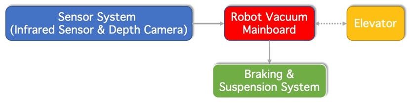
2.1 Block Diagram
Figure 3 to Figure 6 show the main block diagrams of our design.
Figure 3: Block Diagram of Anti-fall Steering Subsystem and Robot Motion Control
Figure 4: Block Diagram of Low Obstacles Passing Subsystem
3Figure 5: Block Diagram of Elevator Interaction Subsystem
Figure 6: Block Diagram of Effective Path-Finding Subsystem
2.2 Subsystem Overview
As illustrated in Figure 1, the complete system consists of two parts, the robot subject and
the matching elevator. When the robot finishes cleaning one floor, it will move toward
the elevator and send signals to call the elevator to lift it up to the next floor. For demon-
stration purposes, we only build a simple lift that can lift the robot up. Figure 2 shows the
robot itself, which is the main part of our design. It has four subsystems, together con-
trolling other peripherals to do the driving and cleaning work. As mentioned in Section
1.2, the four subsystems are Anti-fall Steering Subsystem, Low Obstacles Passing Subsystem,
4Elevator Interaction Subsystem and Effective Path-Finding Subsystem. In the next paragraphs,
we describe all the subsystems and peripherals in detail.
1. Subsystem. Anti-fall Steering
It allows the robot to automatically turn when it approaches the edge of stairs to
avoid falling and this function is completely mechanical and does not require soft-
ware. The function is based on a purely mechanical structure, with a steering wheel
that is perpendicular to the forward direction to achieve steering at the edge of the
step.
2. Subsystem. Low Obstacles Passing
This allows the robot to pass low thresholds or obstacles to avoid getting stuck dur-
ing the cleaning process. In this process, the infrared sensor will be used to detect
whether there is an obstacle in front, and the robot will use the steering gear and
CAM structure to raise the chassis to pass the obstacle.
3. Subsystem. Elevator Interaction
This subsystem is designed for multi-floor cleaning. An assorted simple lift will
be made with an antenna to exchange signals to lift up/down the robot. A state
machine is embedded in the elevator to control its behavior and send signals back to
the robot. For the robot, the microcontroller will manipulate the signals and decide
if the robot should wait or keep cleaning.
4. Subsystem. Effective Path-Finding
This subsystem tells the robot how to find the most effective path for cleaning the
room. Before cleaning, we will let the robot patrol inside the room to collect and
store the 2D/3D surrounding information using a laser radar. Then the robot uses
the improved path-finding algorithm to generate the desired path while taking the
low obstacles into consideration. That means the robot will make a decision on
whether to pass the barrier or bypass it and choose the one with higher efficiency.
5. Peripheral. Driving
The drive unit uses two independent 5V DC stepper motors to control the two driv-
ing wheels, which achieve the steering function through the speed difference. The
driven wheel is only used for support.
6. Peripheral. Cleaning
The unit has the function of wiping the floor and vacuuming. The dust collection
box is located in the center of the robot vacuum, and the vacuum fan is located
behind the dust collecting box, forming a front-to-back air duct. A pair of three-leaf
brushes are arranged in front of the robot vacuum chassis to clean the ground, and
a long roller brush is arranged in the middle of the chassis to assist the vacuum
cleaner to collect dust into the dust box.
52.3 Subsystem Requirements
2.3.1 Subsystem. Anti-fall Steering
Description:
The robot’s ability to automatically turn when approaching the edge of stairs is a critical
safety feature that prevents it from falling and causing damage. This function is achieved
through a completely mechanical structure that does not require any software or pro-
gramming. The robot’s design incorporates a steering wheel that is positioned perpen-
dicular to the forward direction, allowing for precise steering at the edge of a step. This
mechanism works by detecting when the robot is approaching the edge of the stairs and
automatically activating the steering mechanism to turn the robot away from the edge.
This design ensures that the robot is always stable and secure on any surface, making
it ideal for use in environments where safety is a top priority. The purely mechanical
structure of this function also means that it is highly reliable and does not require any
maintenance or software updates, making it an excellent choice for long-term use. Over-
all, the robot’s ability to avoid falling when approaching the edge of stairs is a testament
to its advanced design and engineering, which prioritizes safety and reliability above all
else. The block diagram is shown in Figure 3.
Requirements Verification
The single anti-fall steering wheel Since this part is purely mechanical,
has a diameter of about 60mm*16mm we generally use M3/M5 type screws
thickness, which normally does not and other standard types of bearings.
touch the ground.
Screws and bearings are used to fix it The reliability of this unit needs to be
to the chassis and to fix it to the motor tested experimentally.
through the bearings.
Table 1: Requirement & Verification of Subsystem. Anti-fall Steering
2.3.2 Subsystem. Low Obstacles Passing
Description:
The ability to navigate obstacles is a crucial feature of any robotic cleaning device. The
unit in question enables the robot to detect and pass low thresholds and other obstacles
during the cleaning process, ensuring that it can effectively clean all areas of the room
without getting stuck. The process starts with the robot’s infrared sensor, which scans
the area in front of the robot to detect any obstacles. If an obstacle is detected, the robot
uses its advanced steering gear and CAM structure to lift the chassis of the robot and pass
over the obstacle. The steering gear and CAM structure work together to ensure that the
robot’s movement is smooth and stable, even when passing over uneven surfaces. This
feature is particularly useful in homes and other environments where there may be small
obstacles or thresholds that could impede the robot’s progress. By using the infrared sen-
6sor and advanced CAM structure, the robot can easily navigate these obstacles without
getting stuck or causing any damage to the device or the environment. Moreover, this
unit also makes the cleaning process more efficient and convenient by allowing the robot
to clean larger areas in a shorter amount of time. With the ability to navigate obstacles
with ease, the robot can move freely throughout the room, cleaning all areas thoroughly
without the need for human intervention. The block diagram is shown in Figure 4.
Requirements Verification
For a robot vacuum with a height of The angle and shape of the CAMs also
100mm and a weight of 5kg, a CAM need to be adjusted to the design and
with a diameter of about 50mm and needs of the robot to ensure that the
a height of 10-15mm can be selected. robot can pass smoothly over obsta-
A lightweight material such as alu- cles and uneven ground.
minum alloy is used for the suspen- This requires extensive testing and
sion system, and extensive tests and simulation to determine the best
simulations are conducted to ensure CAM parameters.
the stability and smoothness of the The robot’s suspension system should
robot. be lightweight, durable and easy to
maintain to ensure the long-term sta-
ble operation of the robot.
Table 2: Requirement & Verification of Subsystem. Low Obstacles Passing
2.3.3 Subsystem. Elevator Interaction
Description:
This subsystem’s functionality is useful for the following scenarios: There is a high stair
that separates the room into two parts. The hotel or school has multiple floors to be
cleaned. By letting the robot vacuum automatically interacts with the elevator or lift,
the robot can do multi-level cleaning in one launch. Typically, when the robot finishes
cleaning one floor, it will move onto the elevator and ask the elevator to lift it up/down
by sending signals. Once the antenna on the elevator receives that signal, its state changes
and starts lifting the robot up/down. Once the elevator reaches the next level, it tells the
robot to keep cleaning. So with the wireless signal exchange, the robot moves to the upper
or lower floors and continues working. The block diagram is shown in Figure 5.
7Requirements Verification
The robot can move onto the eleva- A. We test this by verifying whether
tor or move to its direct front during the robot can move toward the eleva-
cleaning. tor in the algorithm simulation.
B. We test this algorithm in a real
room and elevator.
The process of lifting up/down is A. We perform a simulation to test the
smooth, the robot does not get stuck correctness of the elevator state ma-
when entering and exiting the eleva- chine by sending the corresponding
tor. signals once at a time.
B. There will be an outer frame on the
demo elevator, we will examine if the
robot can enter and exit the elevator
without touching the outer frame.
Table 3: Requirement & Verification of Subsystem. Elevator Interaction
2.3.4 Subsystem. Effective Path-Finding
Description:
Since our robot vacuum has the ability to pass low obstacles, we could also apply this
to improve the path-finding algorithm. In specifics, we will upgrade the existing path-
finding algorithm so that for each low barrier in the room, the robot will analyze the
necessity to pass over it. This subsystem is software only, which will be done on a pro-
grammable chip. This subsystem is also the controller of all other subsystems since we
need to generate control signals from the programmable chip. The block diagram is
shown in Figure 6.
Before cleaning, the robot will patrol the room to capture the environment with its laser
radar, including the shape of the room (2D surrounding) and barriers around the room
(3D surrounding). Then, with the collected data, the robot runs the algorithm to try to
find the most efficient path. For low barriers, the software will generate several paths,
some pass over them while some bypass them. We give a heuristic standard to the robot
to choose the best route among all generated routes.
8Requirements Verification
The robot will take the existence of We manually choose an empty room
low obstacles into consideration and and put some low obstacles that do
choose the correct path based on that. not change the most efficient path, we
see if the robot passes them rather by-
passes them.
The complexity of our path-finding A. We will calculate the complexity of
algorithm should be at least at the both algorithms and compare them.
same complexity level as the existing B. We will run the original algorithm
algorithm. If this cannot be the case, and our updated algorithm, keeping
the computing time shall not exceed track of their elapsed running time,
25% of the existing scheme. and making comparisons.
Table 4: Requirement & Verification of Subsystem. Effective Path-Finding
2.3.5 Peripheral. Driving
Description:
For this system, two electric motors need to provide enough power to propel the move-
ment of the vacuum robot. Usually, the weight of the vacuum robot is within 5kg and
the height is below 100mm, so the motor can not occupy too large volume, nor can the
weight be too large. In addition, the size and style of the wheels need to be carefully
chosen. Although the McNamm wheel is currently popular on robots to achieve more
flexible direction changing, for sweeping robots, it does not need very flexible direction
changing ability, but pays more attention to energy consumption and endurance, so we
choose the common rubber wheel. The wheel size matches the robot size, and a wheel
with a diameter of 70mm and a thickness of 16mm is selected as the driving wheel. In ad-
dition, we need a programmable circuit board to achieve the left and right wheel rotation
at different speeds and based on this to achieve the steering function. The block diagram
is shown in Figure 3.
9Requirements Verification
A single motor size needs to be less There are many optional motors in
than 50mm*50mm*50mm and a sin- the network store. The common
gle motor weight should be less than ones are 42.5mm* 42.5mm* 34mm
250g. and the rated voltage is 3.4V, whose
The voltage required by a single mo- weight is 223g. The wheels are also
tor: no more than 5V. very optional in size and can be 3D
The size of a single wheel should be printed.
about 70mm diameter *16mm thick- Wheel speed control can be achieved
ness. using the simplest Arduino-
Programmable circuit board, need programmed circuit board.
to control the motor speed of two
wheels respectively.
Table 5: Requirement & Verification of Peripheral. Driving
2.3.6 Peripheral. Cleaning
Description:
A vacuuming robot is usually equipped with a round body with a removable dust port
and a set of roller brushes on the bottom. When the robot begins to work, the dust port
and brushes begin to rotate, thereby drawing dust and debris from the floor into the
robot’s dust container or bag. The dust container or bag is usually located at the bottom
of the robot and can be easily removed and cleaned.
10Requirements Verification
Motor parameters: The power of the Suction strength: The vacuum cleaner
motor is usually between 10 and 100 module should have enough suction
watts, higher power usually means power to effectively pick up dust, fine
more suction power and higher clean- sand, hair and other debris from the
ing efficiency. floor. You can test the robot by plac-
ing it on different floors to compare its
suction strength and effectiveness.
Rotating brush head parameters: The Cleaning range: The vacuum cleaner
size of the rotating brush head is usu- module should be able to clean hard-
ally between 10 and 20 cm. Some to-reach places such as corners and
high-end robots are also equipped edges.
with rotating brush heads with ad-
justable height and adaptive rotation
speed to accommodate different types
of floors and cleaning tasks.
Dust collection box size: The size of Filter: The filter of vacuum cleaner
the dust collection box usually ranges module should be able to effectively
between 0.3 and 1 liter. Larger dust filter dust and tiny airborne particles
collection boxes can work longer and to avoid releasing them into the in-
reduce the number of interventions door air.
during cleaning.
Table 6: Requirement & Verification of Peripheral. Cleaning
2.4 Tolerance Analysis
The anti-drop function needs to focus on the design of the position of the steering wheel.
It must ensure that the center of gravity of the robot is between the steering wheel and
the two driving wheels, or the robot will fall before the steering wheel works.
Different barriers may have different shapes, if the shape is strange, the infrared sensor
may fail to detect the correct height. We expect the robot to pass the barrier of which the
highest height is less than 2cm. We allow the robot to try but fail to pass over the obstacles
with almost all parts flat but with a sharp structure.
The robot scans the room statically, but new obstacles can be put into the room after
scanning. When the robot meets these obstacles on the planned route, we allow the robot
to either recompute the route or just simply bypass them. In this case, the path might not
be the best, but we accept this deviation.
There may be interference between the driven wheel and the brush. It is necessary to
consider whether the brush can be used to replace the driven wheel to achieve support or
reduce the size of the driven wheel.
113 Ethics and Safety
3.1 Ethics
Privacy:
Robot vacuum cleaners should be designed to respect the privacy of individuals. This
means that they should not collect or transmit personal data without the explicit consent
of the individual. If data is collected, it should be stored securely and deleted when it
is no longer necessary. This is in compliance with ACM Code of Ethics and Professional
Conduct Clause 1.6 Respect privacy [1].
Safety:
Robot vacuum cleaners should be designed to prioritize safety. This means that they
should be equipped with safety features to prevent accidents, and should be tested rigor-
ously to ensure that they do not pose a risk to individuals or property.
Transparency:
Robot vacuum cleaners should be designed with transparency in mind. This means that
individuals should be informed about what data is being collected and how it will be
used. In addition, any limitations or potential risks associated with the device should be
clearly communicated. This is in accordance with ACM Code of Ethics and Professional
Conduct Clause 1.2 Avoid harm [1].
Accessibility:
Robot vacuum cleaners should be designed to be accessible to all individuals, regardless
of their physical or cognitive abilities. This means that they should be easy to use and
operate, and should be designed with universal design principles in mind. This is in
conformity with ACM Code of Ethics and Professional Conduct Clause 1.4 Be fair and
take action not to discriminate [1].
In addition to these key principles, the code of ethics for robot vacuum cleaners should
also include guidelines for testing and certification, as well as guidelines for account-
ability and responsibility. This can help ensure that manufacturers and users are held
accountable for any ethical lapses that may occur.
3.2 Safety
One of the primary safety concerns for robot vacuum cleaners is the risk of collision.
These devices are designed to navigate around obstacles and furniture, but they can still
accidentally collide with objects or people. This can result in damage to the device, as well
as potential injury to individuals or damage to property. To mitigate this risk, robot vac-
uum cleaners should be equipped with sensors and other safety features to help prevent
collisions.
Another safety concern is the risk of entanglement. Robot vacuum cleaners typically have
brushes or other mechanisms that can become entangled in cords, rugs, or other items on
the floor. This can cause the device to become stuck or damaged, and can also pose a risk
12of injury to individuals or pets. To address this concern, robot vacuum cleaners should
be designed with safety features to prevent entanglement, such as automatic shutoffs or
sensors that detect when the device is stuck.
In addition to these concerns, there is also the potential for electric shock or fire. Robot
vacuum cleaners are electrical devices, and as such, they can pose a risk of electric shock
or fire if not used properly or if there are defects in the device. To mitigate this risk, robot
vacuum cleaners should be designed with safety features such as automatic shutoffs or
surge protectors to prevent electrical hazards.
Overall, the safety concerns for robot vacuum cleaners can be addressed through careful
design and testing, as well as clear communication to users about proper use and poten-
tial risks. By prioritizing safety in the design and use of these devices, we can ensure that
they are a safe and useful addition to our homes.
13References
[1] ACM. (2018). “ACM Code of Ethics and Professional Conduct,” [Online]. Available:
https://www.acm.org/code-of-ethics (visited on 03/08/2023).
14You can also read