Research on maintenance tools of wire clamps for live working on Ultra High Voltage transmission lines
←
→
Page content transcription
If your browser does not render page correctly, please read the page content below
E3S Web of Conferences 261, 01063 (2021) https://doi.org/10.1051/e3sconf/202126101063
ICEMEE 2021
Research on maintenance tools of wire clamps for live working
on Ultra High Voltage transmission lines
Zhigang Wang 123, Wenjian Mei 123, Qi Yang123, Mingming Qiao123 Jianping Chen123 and Peng Li123*
1Live Line Operation Center, Power Transmission Maintenance Branch of State Grid Hunan Electric Power Co., Ltd., ChangSha, Hunan,
410000, China
2Intelligent live working technology equipment (robot) Hunan Provincial Key Laboratory, ChangSha, Hunan, 410000, China
3Live inspection and intelligent operation technology State Grid Corporation Laboratory
Abstract. Aiming at the problem that the suspension clamp is difficult to be quickly replaced due to the
heavy load of the suspension clamp when replacing the transmission line wire suspension clamp in the UHV
live operation, this paper develops an auxiliary device for realizing the rapid replacement of the conductor
suspension clamp. Through the design of fixtures suitable for the installation of UHV wires and connecting
plates, the load transfer of the suspension clamp can be quickly realized, and the suspension clamp can be
separated and replaced under the condition of no force. The device is flexible and light, and effectively
improves the live working personnel work efficiency.
of failure continues to increase [1]. At present, the load of
the entire set of wires is usually transferred with the aid of
1 Introduction cross arm clamps, wire rods, insulated pull rods and wire
The Qishao ±800kV UHV DC transmission line is an hooks. The tools are heavy, the transfer load is large, the
important power transmission project for the country's operation is difficult for the operators, and it takes a lot of
"West-East Power Transmission". Its line spans the 5 time and physical strength, which brings great safety Risk
provinces of Gansu, Shaanxi, Chongqing, Hubei and [2,3]. [2,3]. In response to this problem, a "UHV
Hunan, with a total length of 2,383 kilometers. The transmission line wire suspension clamp fixture" was
corridors of the line are complicated. Some lines have developed to transfer only the required sub-conductor load
long been tested by severe weather such as sandstorms, to efficiently complete the live replacement of the UHV
high temperatures, blizzards, and severe cold. With the transmission line suspension clamp work.
commissioning and long-term operation of Qishao UHV
transmission lines, transmission line failures continue to 2 requirements of the design
increase, and the demand for maintenance devices for live
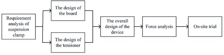
work is also increasing. According to the functional requirements, this article
Suspension clamps are commonly used fittings on designs each part of the suspension clamp fixture, which
transmission lines, and their main function is to fix the is divided into the design of the board card, the design of
wires on the insulator string of the linear tower. During the tightener part, and the overall design. Finally, the
the long-term operation of the line, the suspension clamp mechanical calculation is used to check whether the tool
is exposed to the natural environment for a long time, and meets the requirements. The specific design idea is shown
is constantly subjected to various severe weather tests in Figure 1.
such as strong winds and sandstorms, and the probability
Figure 1 Design ideas of suspension clamp
*Corresponding author’s e-mail: lipeng@stu.hut.edu.cn
© The Authors, published by EDP Sciences. This is an open access article distributed under the terms of the Creative Commons Attribution License 4.0
(http://creativecommons.org/licenses/by/4.0/).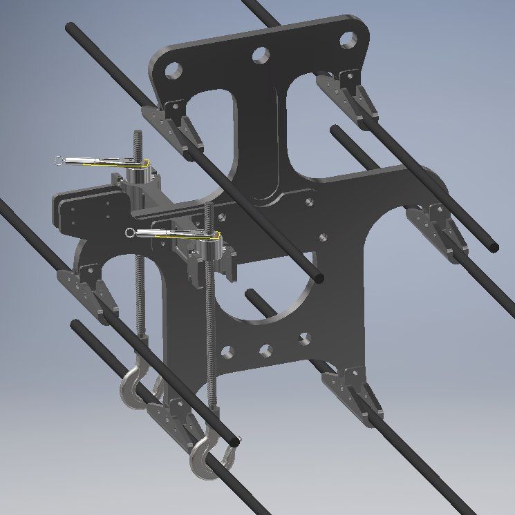
E3S Web of Conferences 261, 01063 (2021) https://doi.org/10.1051/e3sconf/202126101063
ICEMEE 2021
The specific instructions are as follows connecting board uses bolts 1 to fix the flat board on the
(1) Analyze the structure of the connecting plate, the connecting board, and the reserved screw holes 2 are used
suspension clamp and the conductor, and design a fixture to fix the wire tensioner bracket, with stable connection,
that can replace the suspension clamp only by transferring flexible disassembly and assembly, and strong reliability.
the required sub-conductor load;
(2) Analyze the stress on the middle and lower lines of
3.3 Tighter bracket design
the transmission line, and design corresponding
components according to the requirements; Based on the design of the tie-board card and the tensioner,
(3) Compare the maximum line load of Qishao Line it is necessary to design a tensioner bracket that can fix the
with the mechanical load of the tool, and redesign if it does tensioner on the tie-board card to ensure that the tensioner
not meet the requirements; can firmly press during the tightening process. On the
(4) The complete set of tools includes the board clamp, connecting board, the designed cable tightener bracket is
the wire tensioner bracket, the suspension screw, the shown in the figure. The analysis shows that the wire
support screw and the wire fixing frame, and its design, tensioner bracket is fixed on the coupling plate by bolts,
development, improvement and manufacturing must meet and the screw rod is fixed by the tenon joint.
the "State Grid Corporation Electric Safety Work
Regulations Line Part" And the relevant provisions of the
"Basic Requirements for Design and Testing of
Transmission Line Construction Equipment".
3 Device configuration and processing
3.1 Composition and principle Figure 2 Schematic diagram of connecting board
UHV transmission line wire suspension clamp fixture is
composed of joint board clamp, wire tensioner bracket,
screw rod and wire fixing frame. Use the tie-board card as
a fixed holder, and use tools such as the wire tensioner
bracket, screw rod, and wire fixing frame to lift the wire.
The device uses the connecting plate as a support point to
lift a single wire, and each end of the connecting plate has
a set of devices. Therefore, the force of a single screw is
only half of the load of the replaced sub-wire, and the tool
takes up less space and the safety factor is greatly Figure 3 Schematic diagram of the tensioner bracket
improved.
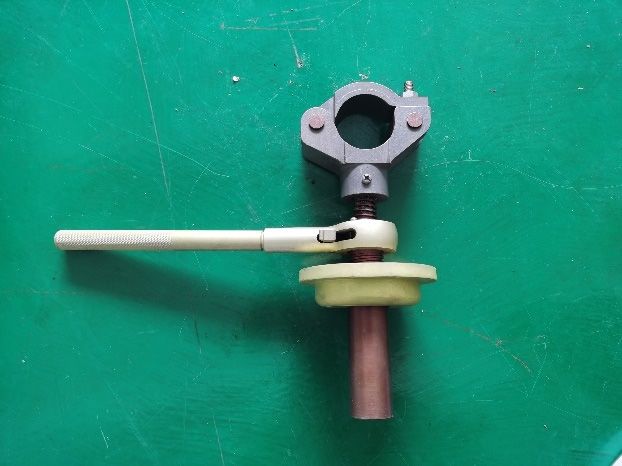
3.4 Wire tensioner
3.2 Union board design
Due to the limitation of the connecting board structure, the
The main function of the connecting board is to connect connecting board card and the wire tensioner bracket can
the tensioner bracket and the connecting board, so that it only be erected in the middle of the connecting board. The
can move synchronously. The symmetrical midplane of stress situation of the upper, middle and lower wires is
the traditional big knife chuck surface has a through slot analyzed, and two different wire lifting methods and two
with a thickness that matches the connecting plate of the wire fixing frames as shown in the figure are designed.
circuit fittings. The connecting plate of the wire is closely As shown in Figure 4(a), the support screw: used for
attached to the through slot, and the knife edge forms a load transfer on the upper wire, and closed support claws
mechanical fulcrum through the connecting plate bolt, but are used to prevent the wire from slipping out, and the
the UHV circuit is connected The board space structure is safety is high; as shown in Figure 4(b), the suspension
complicated, and the practicability is not high. Therefore, screw: used for middle and Under the wire load transfer,
the design of the flat card as shown in Figure 2. The design the wire hook as shown in the figure 4.
2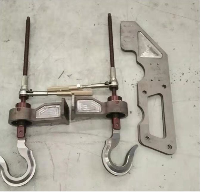
E3S Web of Conferences 261, 01063 (2021)                                                         https://doi.org/10.1051/e3sconf/202126101063
ICEMEE 2021

                  (a)Schematic diagram of support screw                        (b)Schematic diagram of suspension screw

                                                 Figure 4 Schematic diagram of the tightener

                                                                         The picture shows the assembly diagram of the new type
                                                                         of suspension clamp, which is divided into two types: (a)
      4 Assembly test and application                                    wire lifting type and (b) wire top type. As shown in the
                                                                         figure, the two styles are mainly composed of a
      4.1 Overall assembly                                               connecting plate, a wire tensioner bracket, and a wire
                                                                         tensioner. Each part is connected by bolts and tenon joints.

                                (a) Wire lifting type                                   (b)Wire top type

                                               Figure 5 Schematic diagram of overall assembly

                                                                         selected for calculation. The basic parameters of the
                                                                         selected line are:
      4.2 Mechanical calculation
      According to the situation of the entire Qishao line, the
      line with the largest wire type and the largest line span is
                                                          Table 1 Wire parameters

                              parameter                                                  value

               Wire model                                  JL1/G2A-1250/100
               cross-sectional area (mm2)                  1350.03
               Outer diameter(mm)                          47.85
               Calculated weight (kg/km)                   4252.3
               Calculate breaking force (N)                329.85
               Span(m)                                     879
               Vertical span(m)                            772

          It is carried out in good weather, without ice, and wind       fittings and the load caused by wind pressure are
      speed is not greater than 5 levels. Therefore, in the              considered.
      relevant calculations, only the weight of the wires and

                                                                     3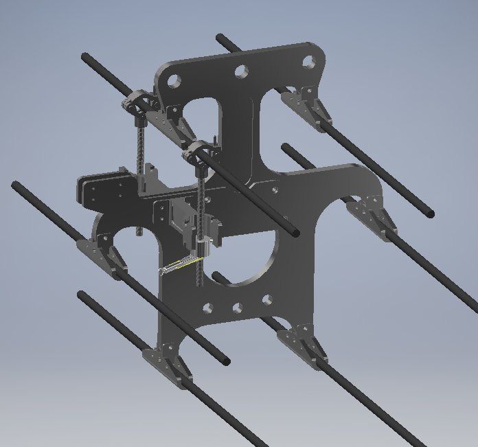
E3S Web of Conferences 261, 01063 (2021) https://doi.org/10.1051/e3sconf/202126101063
ICEMEE 2021
4.3 Calculation and Analysis of Force on Linear G0
Tower g1 =30.86 10 -3( N /m mm 2) (1)
S
It is carried out in good weather, without ice, and wind g0
speed is not greater than 5 levels. Therefore, in the -wire weight per kilometer (kg/km), S The
relevant calculations, only the weight of the wires and entire cross-sectional area of the wire.
fittings and the load caused by wind pressure are (2) Wind pressure P
considered. The wind pressure on the wire is caused by air
(1) Self-weight load of transmission wire movement energy. The horizontal wind pressure in the
vertical line direction is:
V2 2 11.1100 47.85
P KF sin (9.8N) =24.36 10-3(N/m mm 2) (2)
16 1.6 1350.03
-coefficient of uneven wind speed 1.0, wind speed
power line sin 1 , K - Aerodynamic coefficient
2
10m/s, F -The projection surface of the wind surface on 1.1.
plane perpendicular to the wind direction, The
(3) Comprehensive ratio
a
horizontal angle between the wind direction and the wind g6 g12 g 42 39.31 10 (
3
N /m mm 2) (3)
projection surface, When calculating, consider that the (4) Vertical load on the insulator string
wind direction is perpendicular to the direction of the
Q g1 Slz W 30.86 10 3 1350.03 772 100 9.8 33143.01N (4)
Where K Including spacer rods, pull plates, wire
clamps and the weight of the equipotential operator, it is
approximately 200kg (the weight of composite insulators 5 Conclusion
is not considered, ±800kV UHV lines are six-split The clamp fixture designed in this paper is used in the
conductors) maintenance work of the live replacement of the UHV
(5) Horizontal load on the insulator string transmission line, and the suspension clamp operation
P g 4 Slp 20422.66 N (5) time is reduced from 3 hours to 1.4 hours. It greatly
(6) The total load on the insulator string is reduces the labor intensity of the operators and improves
the efficiency of equipment maintenance.
G Q 2 P 2 38929.99 N 38.9kN (6)
(7) Total load on a single sub-conductor is
The load strength of a single hanging wire clamp Acknowledgments
fixture is 40KN, and the load strength of the whole set of This article was funded by the special scientific research
fixtures is 80KN, which is much larger than the total load project of the Ministry of Science and Technology of the
of a single wire, so it meets the operating requirements. State Grid Hunan Electric Power Co., Ltd. "The method
and equipment for live operation of Qishao Ultra High
4.4 On-site trial Voltage, 5216A318000R"
In order to verify the actual effect of the device, the live
operation center of the State Grid Hunan Power references
Transmission Maintenance Company carried out the live
replacement of the UHV transmission line simulation 1. Yang Shiqiang, Weng Yongchun, Li Xiaolai, et al.
operation at the training site, and the following work flow Analysis and Research on Hidden Dangers of Uneven
was formulated: Ice Coating Damage to UHV DC Fittings[J]. Hubei
(1) The ground electrician connects the wire fixing Electric Power, 2018, 042(003): 5-8, 25.
device with the screw rod in advance, and then 2. Zhang Zisheng, Zhou Cheng, Huang Jing.
successively transmits each part of the device to the Development and application effect analysis of live
electrician on the tower through the insulating rope; working tools for ±800kV UHV DC transmission
(2) Two equipotential electricians first fix the lines[J]. Science and Technology Innovation and
connecting plate clamp on the wire connecting plate, then Application, 2019(35).
install the tensioner bracket and the tensioner one after 3. Wu Zhengshu, Fan Changhai, Tao Huiying, et al.
another, then tighten the tensioner, and replace the wire Analysis on the method of live replacement of the
clamp after the load transfer is completed. wire clamp of the linear tower of ± 800kV DC
transmission line[J]. Guangxi Electric Power, 2014.
4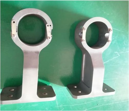
You can also read