Readout System and Testbeam Results of the RD50 MPW2 HV-CMOS pixel chip - Patrick Sieberer RD50 HVCMOS group - CERN Indico
←
→
Page content transcription
If your browser does not render page correctly, please read the page content below
Readout System and Testbeam Results of
  the RD50 MPW2 HV-CMOS pixel chip
   Patrick Sieberer
   RD50 HVCMOS group
Setting the stage…

        INTRODUCTION

23.06.2021                   38th RD50 Workshop   2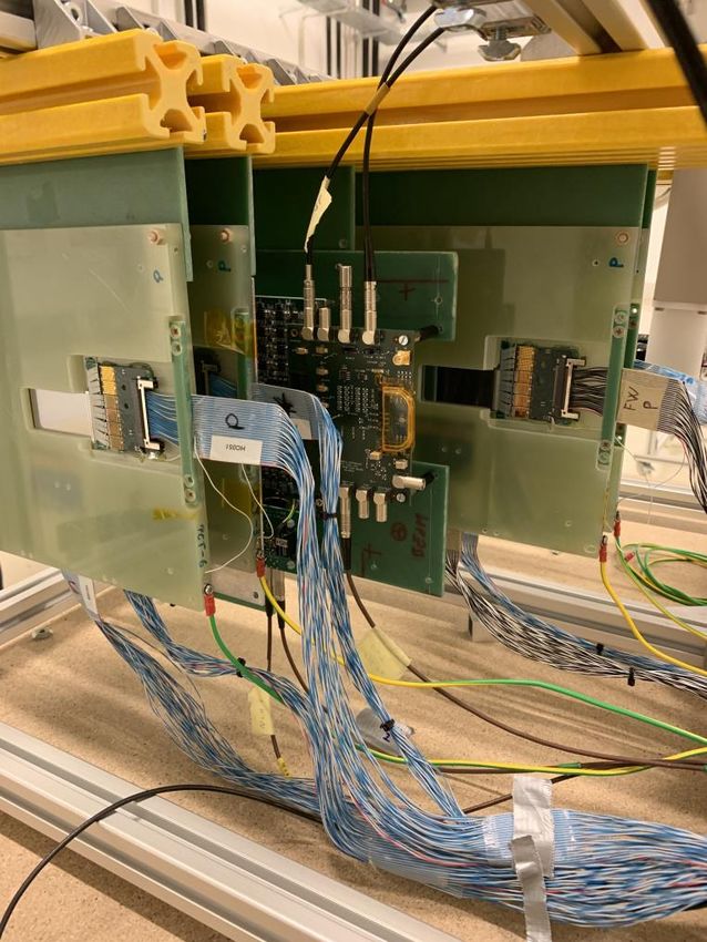
• 64 pixels, 60µm x 60µm
     • Two flavors of readout:
             – Continuous reset (Col 0-3)
             – Switched reset (Col 4-7)
     • Bias-Block: Generates bias
       voltages to set the transistor
       operating points
     • Configuration Registers: for
       Bias-Block and pixel
       TRIMDAC voltages
     • Analogue buffer and
       multiplexer to monitor voltages
       and analogue pixel readout

                                                          continuous   switched

23.06.2021                           38th RD50 Workshop                           3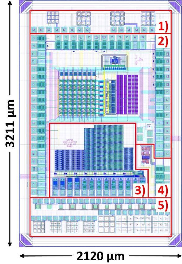
Example: Switched Reset Pixels
                           Amplifier +
                           feedback loop
             Injection     for reset
             Circuit
                                                Trimable Comparator

                                                                 Comparator
                                                                 Output

                         Source Follower
                         Output
23.06.2021                 38th RD50 Workshop                                 4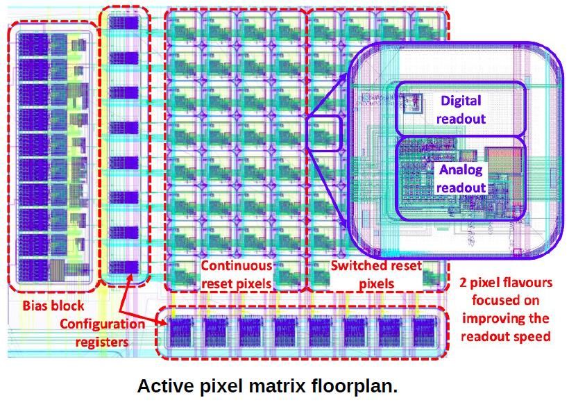
READOUT ELECTRONICS

23.06.2021      38th RD50 Workshop   5
More details on Hardware
See C. Irmler's talk at 36th
RD50 workshop
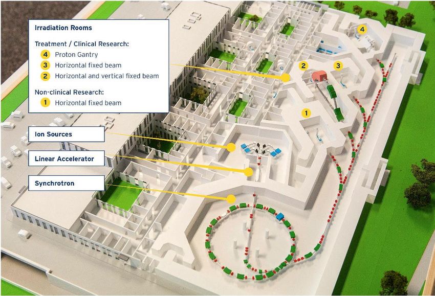
and Caribou:
Paper published at PoS
(Tomas Vanat)
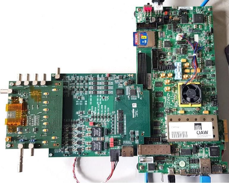
Caribou
Run Control
(EUDAQ) AIDA TLU
RD50 MPW2
• HV supply
• Scintillators
• Sr90 source
MPW2-chip board CaR-Board SoC (ZC706)
23.06.2021 38th RD50 Workshop 6
•    Open source hardware, firmware and
          software for laboratory and high-rate
          beam tests
     •    Developed & maintained by collective
          effort from:

     •    Goal: Provide a modular and versatile
          DAQ system which
             –   minimizes device integration effort
             –   reduces time to get first data from a new
                 detector
     •    System on Chip (SoC) running Linux
          and DAQ software on Processing
          System (PS) and detector control and
          data processing on Programmable
          Logic (PL)
     •    Periphery CaR board provides
          physical interface between SoC and
          detector
     •    Application-specific chip board

  Slide provided by Eric Buschmann

23.06.2021                                          38th RD50 Workshop   7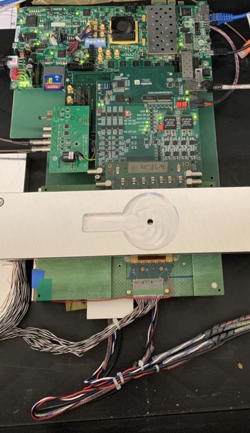
•   Provides interface from FPGA/SoC to detector
      chip and hardware resources
       –     Adjustable power supplies with monitoring
       –     Adjustable voltage and current references
       –     Slow (50 kSPS) 12-bit and fast (65 MSPS) 14-bit ADC
       –     Programmable injection pulsers
       –     Full-duplex high-speed GTx links (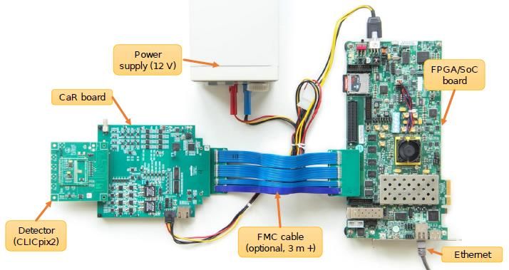
• COMPOUT connected to FPGA Software:
• Simple ToT measurement implemented Costume EventLoader
in FPGA written for EUDAQ
• ToT and Hit Counter written to AXI RunControl
FIFO of the Evaluation Board caribou-class written for
MPW2
• AXI FIFO readout by Caribou-Peary Not part of the official
– Simple peary module written to store caribou repository yet
ToT and Hit Counter in a ASCII file
Counter
ToT- clk_200MHz clk
Counter out
ToT
Counter
16 bit
count_enable (AXI FIFO)
COMPOUT_b Pos. edge out reset
in
uf
detector
standalone firmware Shaper Async. out Hit Counter
in out clk
25ns Counter 16 bit (AXI FIFO)
-> Simple Readout Chain, using only the Caribou-Board for Slow Control and Data Path
-> Can already be used for injection pulses and with a radioactive source
23.06.2021 38th RD50 Workshop 9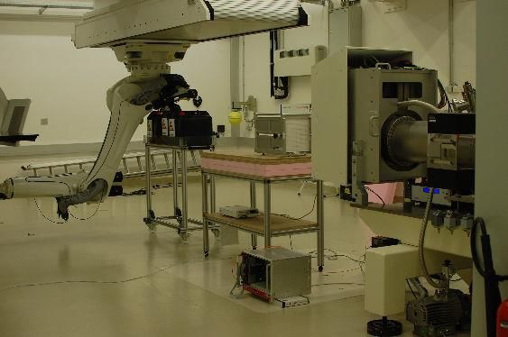
•   Hit-maps at -50V Bias
     •   3 different fluences
     •   Sr90 source (10mCi)
     •   Noise subtracted

         Wafer 13, unirradiated           Wafer 13, 3e13Neq           Wafer 13, 1e14Neq

             For more results, see this talk from P. Sieberer at 37th RD50 workshop
23.06.2021                            38th RD50 Workshop                                  10
TESTBEAM FIRMWARE 23.06.2021 38th RD50 Workshop 11
trigger_tlu
TS Counter
t0 + Δt + Delay
out
8 bit =
FIFO AXI FIFO
t0 TS Counter out D_8 Q_8
write enable
8 bit 8 bit
ToT Counter out D_16 Q_16 D_16 (ToT)
16 bit 16 bit
Particle_hit
write enable
read
testbeam firmware = Trigger nr. (TLU) out
D_16 (Trigger Nr)
ToT Counter + trigger logic
16 bit
• Every hit stored in the FIFO (ToT + internal TS)
• Delayed TS is computed and compared with first TS
• Data (ToT value + Trigger Number from TLU) only to AXI FIFO, when there is a trigger issued
Synchronization effort:
Delay of TS Counter needs to match the Trigger Delay
Particles that hit pixel, without issuing a trigger are not stored. (Important for events
that are not recorded by the (slower) telescope, or do not hit scintillators anymore
due to too low energy, …)
23.06.2021 38th RD50 Workshop 12• Trigger delay needs to be determined.
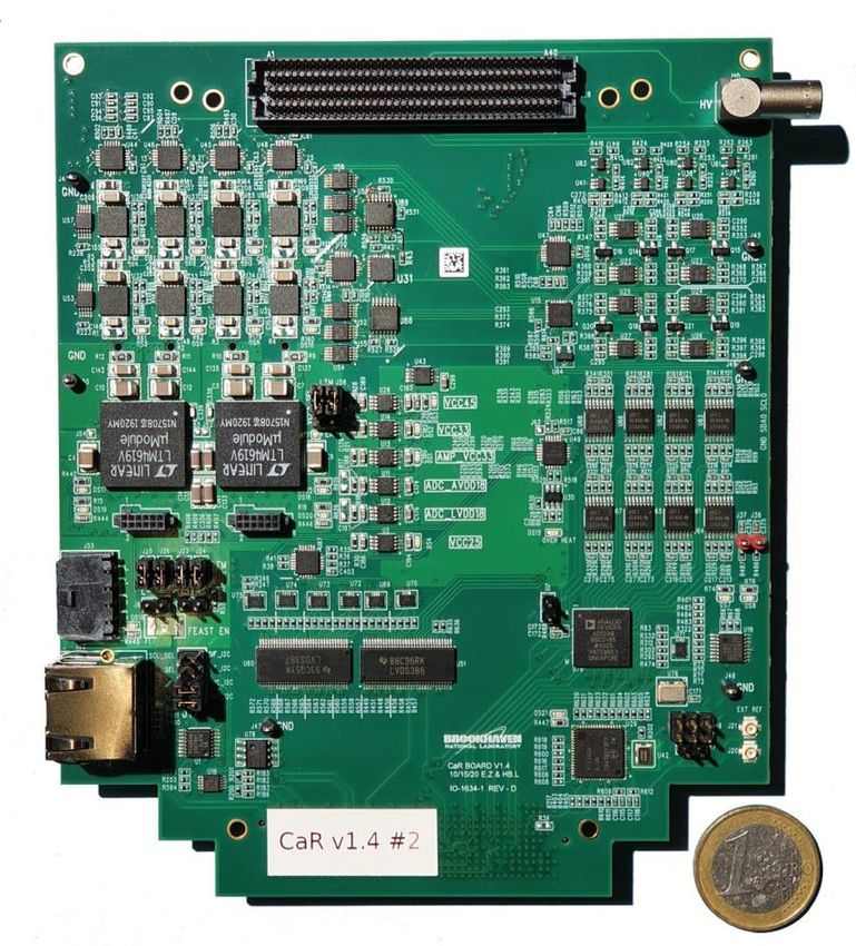
holder for Sr90 source
telescope plane
RD50-MPW2
scintillator
mpw2_hit_out
• Overall data rate: ~1 particle every minute
• Geometric acceptance, rate reduction due to absorption
• We can be sure that if we measure a particle on RD50-MPW2 + scintillator,
the recorded data belongs to the same particle
• No particle at all will be recorded, if delays don’t match
• Δt = Difference between mpw2_hit_out and trigger output of the TLU
23.06.2021 38th RD50 Workshop 13TESTBEAM AND ANALYSIS 23.06.2021 38th RD50 Workshop 14
Testbeam done at MedAustron:
      • 60-800MeV protons
      • “Low Flux”, e.g. ~3.5 MHz particle
        rate
      • 3cm spot size
      • Spill structure: 5s with 2.5s pause
      • Paper published in NIM-A (F.
        Ulrich-Pur)
      • Event rate of telescope: 30kHz

      Detectors used:
      • 4 DSSDs as telescope
             –   APV25 based readout (used in CMS tracker)

      •   RD50-MPW2 as DUT
      •   Scintillators in the back
      •   Triggered with AIDA-TLU

23.06.2021                                     38th RD50 Workshop   15
Alignment: Only single
hit events allowed
(~10% of data)
Analysis: 1-3 hits per
event allowed (~30% of
data)
• Corryvreckan (= tool used for track reconstruction and analysis) only supports
pixels -> Strip information from DSSDs converted into pixels (in Eventloader)
• Problem of ghost hits: much more (~squared) hits reconstructed
• Chance of associating a particle to a ghost hit (‘bad data’)
• Cuts in maximum allowed hits are a trade-off between data quality and statistics
23.06.2021 38th RD50 Workshop 16Residuals telescope plane 3 Residuals DUT
• Residuals (after alignment) of telescope ~40um
• Residuals of DUT should be similar (Binary information from a single pixel
only -> No charge sharing information, COG, …)
• ~38um, due to much less hits (not every reconstructed track also hits
pixel in MPW2)
• Spread of residuals mainly due to multiple scattering in air. (Low beam
energy of 250MeV)
• Straight line tracking used
23.06.2021 38th RD50 Workshop 17• During analysis, GBL is used for tracking
• Chi2 still rather high due to multiple scattering
• Better than straight line (~13)
• Very low statistics not suitable for further analysis
23.06.2021 38th RD50 Workshop 18CONCLUSION AND OUTLOOK 23.06.2021 38th RD50 Workshop 19
• Digital DAQ system gives consistent results
     • Integration to analysis software is working
     • Telescope and RD50-MPW2 data are consistent
       (timing and triggering is working)
     • Lessons learned in RD50-MPW2 will be useful for testing
       RD50-MPW3

     • RD50-MPW3 currently designed
             – Improved analogue performance
             – Full (on-chip) digital periphery
                • Capability to read out full pixel matrix
             – Submission expected in October 2021

23.06.2021                            38th RD50 Workshop         20
BACKUP 23.06.2021 38th RD50 Workshop 21
• RD50-MPW1 (2017)
– High leakage current
– Low breakdown voltage
– Some issues: crosstalk, voltage drop, readout
• RD50-MPW2 (2019)
– Ileak
– Vbd
– Analog pixels only
– Digital DAQ only
in FPGA
• More results:
– Talk from S. Powell at 35th RD50 workshop
– Talk from M. Franks at 36th RD50 workshop
23.06.2021 38th RD50 Workshop 22• LFoundry 150nm process
• Different Wafer resistivities and
fluences available
• Passive test-structures 1)
• Active matrix of DMAPS pixel,
including analogue readout 2)
• SEU tolerant memory array 3)
• Bandgap reference voltage 4)
• Test structures with SPADs 5)
• Details on 3) and 4): See talk from R.
Marco Hernandez at 36th RD50
workshop
• Details on 1): See talk from M. Franks
at 36th RD50 workshop or from R.
Marco Hernandez at VERTEX 2020
23.06.2021 38th RD50 Workshop 23Switched Reset Pixel Continuous Reset Pixel 23.06.2021 38th RD50 Workshop 24
INJECTION PULSES

23.06.2021       38th RD50 Workshop   25
•   Finding the comparator
         threshold
     •   Comparator baseline (BL) at
         900mV (subtracted in plot)
     •   Threshold at 950mV
     •   1000 Pulses per voltage step
         (Step size 10mV)
             – Sigmoid function fitted
             – Counted after COMPOUT

             -> Threshold of Continuous Reset Pixels higher than for
             Switched Reset pixel
             -> Quite some variation between pixels -> TRIMDACs
             implemented for compensation

23.06.2021                           38th RD50 Workshop                26
• Highest possible pixel
sensitivity if comparator
threshold just slightly above
noise-level
• Adjust TRIMDACs: Lowest
possible value, where number
of hits is below a certain
threshold
– Shutter 2s
– Highest possible DAC with nr.
of hits >0 (Better sensitivity
than lowest TDAC with 0 hits)
• The goal is NOT to decrease
the spread of the S-Curves
11 pixels masked (noisy)
23.06.2021 38th RD50 Workshop 27• Highest possible pixel
sensitivity if comparator
threshold just slightly above
noise-level
• Adjust TRIMDACs: Lowest
possible value, where number
of hits is below a certain
threshold
– Open a shutter for 2s, count
(noise) hits
– Highest possible DAC with nr.
of hits >0 (Better sensitivity
than lowest TDAC with 0 hits)
• The goal is NOT to decrease
the spread of the S-Curves
23.06.2021 38th RD50 Workshop 28• Average number of hits per voltage plotted
– No noise subtracted
• Small effect (see backup)
• Doubles measurement time
-> More hits for switched reset pixels (Lower threshold)
-> Less hits seen for higher fluences (both pixel flavors)
-> Continuous reset pixels less effected by fluence (to be confirmed)
23.06.2021 38th RD50 Workshop 291. Set Bias Voltages
2. Adjust TRIMDACs per pixel This peak
as mentioned before includes
– Needs to be re-done if noisy pixels
environment changes (light,
temperature, …)
3. Put radioactive source (Sr90,
10mCi / 370MBq) on top
4. Open a Shutter window (20s)
for each pixel and count
amount of hits
Top: Distribution of adjusted TRIMDAC
values for pixels
Bottom: Example Hit-map without source
23.06.2021 38th RD50 Workshop 30TESTBEAM 23.06.2021 38th RD50 Workshop 31
• Testbeam at MedAustron with protons
              – Ion cancer treatment (GHz rate)
     • 2 different “Low Flux”- Settings used
              – Complete different beam settings, thus different rate
     • Beam Energy: 252.7 MeV (both settings)
     • Particle Rate: 2.2MHz and 400kHz
     • Beam – Spotsize: ~7mm (both settings)
              – All particles hit scintillators
              – Very few particles hit a
                pixel (60um x 60um)

    Setting             Mean Rate     StdDev Rate
    I (at 252.7 MeV)    2.25e6        1.87e5
    II (at 252,7 MeV)   3.92e5        1.86e4

23.06.2021                                 38th RD50 Workshop           32
• Medical Accelerator close to Vienna
• 3 clinical irradiation rooms + 1 additional room for research
• Particle rate: ≥=1010 (protons), ≥ 108 (carbon ions)
• Spill structure: 5s spill, 5s pause
• Beam energy: [60,800] MeV
23.06.2021 38th RD50 Workshop 33• Just one Pixel for one rate ramped over HV (20V stepsize)
• Better performance for higher bias voltage (as expected)
• Follows expected sqrt(U) function, but low statistics
23.06.2021 38th RD50 Workshop 3423.06.2021 38th RD50 Workshop 35
• flexible, fast and lightweight test beam data
       reconstruction framework based on a modular
       concept of the reconstruction chain
     • Costume ‘Eventloader’ for telescope and DUT
       written
             – Alignment, clustering and tracking
             – Analysis for efficiency and resolution
     • https://cern.ch/corryvreckan

23.06.2021                       38th RD50 Workshop     36
Simulation Data
Testbeam results
• Switched reset pixel -> ToT at
• 800MeV protons
~30ns for all energies
• Switched Reset Pixel
• Threshold: 60mV above baseline
AMPOUT from 1-25ke-
~30ns
C. Zhang RD50-MPW2 Documentation
ToT time bins: 5ns
• Standalone Firmware can be used
• Testbeam results measured with ToT counter in FPGA in agreement with simulations
• More results soon
23.06.2021 38th RD50 Workshop 37• Synchronization not easy: Both firmware
versions implemented in parallel in the FPGA
– Problem: only 15bit for Trigger number, much higher
data rate -> overflow!
– Hit counter of firmware version 1 used to count trigger
overflows
– Trigger-number (of firmware version 2) corrected for
overflows in readout software
23.06.2021 38th RD50 Workshop 3823.06.2021 38th RD50 Workshop 39
•   ROI of 3x3 pixels
                        •   Active Pixel is R3 C4 (switched
                            reset)
                        •   Middle pixel of ROI changed for
                            each analysis.
                        •   E.g. Measurement of Pix R3 C5:
                             – all tracks in shown ROI accepted
                             – Still Pix R3 C4 measured
                             – Due to measured pixel still in ROI
                               + charge sharing of tracks right
                               from the pixel, we still see hits

23.06.2021   38th RD50 Workshop                                     40
You can also read