PREDICTIVE MAINTENANCE SYSTEM - MAXIMIZE PRODUCTION AND PROFITS WITH IIOT
←
→
Page content transcription
If your browser does not render page correctly, please read the page content below
PREDICTIVE
    MAINTENANCE
    SYSTEM
    Maximize production and
    profits with IIoT

PREDICT FAILURES. PREVENT DOWNTIME. ENHANCE SAFETY.
•    Remote equipment monitoring solution empowers your asset managers to make
     better maintenance decisions using real-time, actionable data.

•    Cost-effective, end-to-end wireless solution combined with hardwired Ethernet I/P™
     communication to optimize maintenance spends and enhance plant productivity and uptime.

•    Fully configurable and easy-to-deploy hardware architecture with intelligent edge
     processing to suit your unique application needs.

•    A user-friendly and intuitive web application combined with secure data storage
     provides boundless opportunities for data retrieval, visualization, analysis, and reporting.

•    Worker safety is enhanced by reducing hands-on and unplanned reactive
     maintenance activity.

FOR MORE INFORMATION VISIT GRACESENSE.COM OR CALL 1.800.280.9517
SYSTEM OVERVIEW
The field-proven GraceSense™ Predictive Maintenance System is a suite of smart devices that utilize low-power wireless A Leading Automobile
sensor technology. Advanced data analytics provide asset managers with deep insights to machine health to effectively prioritize
resources and maximize the value of their maintenance spend. GraceSense™ technology improves overall plant reliability, safety, Manufacturer has seen
15X ROI in 24 Months
and maintenance metrics by remotely monitoring the asset health and sending timely notifications through SMS or email alerts when
anomalous behavior is detected.
GraceSenseTM Predictive Maintenance technology
captured 28 Million data points and provided
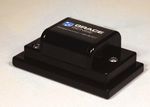
VIBRATION & TEMPERATURE NODE
alerts that prevented eight downtime incidents,
Rugged wireless sensor with advanced edge processing and proprietary Zigbee compatible avoiding over $2 Million in losses.
communication monitors vibration and temperature to insightfully predict health on any rotating
equipment. Multiple mounting options ensure quick deployment across applications in any industry.
Easy to replace batteries deliver 3-5 years of life (dependent on use).
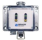
PANEL-MOUNT™ NODE OR CLOUDGATE™ PLCs/SCADA/HMIs
Configurable hardware architecture with a wide selection of inputs, transducers, radios, and power
options. Nodes can be mounted in our environmentally rated housing. Configured as a CloudGate™ API
with an LTE or WiFi module, it can provide cloud-based support to thousands of other wireless nodes
within a 30m radius, making the architecture massively scalable.
Appearance of product shown to the left may change based on final product configuration.
HOT SPOT MONITOR (HSM)
GraceSense™ Hot Spot Monitor is a non-conductive temperature monitoring device that detects
potential hot spots and alerts personnel of any temperature anomalies occurring in electrical
equipment. Additionally, by integrating HSM with a panel-mount node, data from the HSM can be
remotely monitored along with other equipment parameters in the Maintenance Hub.
For more information on the Hot Spot Monitor (HSM) please refer to the product specific datasheet.
Panel-Mount™
CloudGate Vibration &
MAINTENANCE HUB Hot Spot Monitor
Temperature
(HSM)
Node
The Maintenance Hub is an intuitive web application providing real-time asset status using dashboards,
plot trends, and analytics. Hosted either in the cloud or on a local server, the Maintenance Hub displays
system information, generates reports, and issues alerts via SMS and email containing actionable
step-by-step remediation instructions. An open API lets you share data and alerts with existing systems
(i.e. CMMS, SCADA, DCS). Some of the unique capabilities include:
• On-premise Audit Tool • Performing statistical calculations on sensing
• Multiple alert levels per channel channels and displaying their values on the Temperature
Panel-Mount™
• Virtual channels that mathematically combine dashboard Node Node
data from multiple sensors in real time
FOR MORE INFORMATION VISIT GRACESENSE.COM OR CALL 1.800.280.9517
© Grace Technologies All rights reserved. Specifications are subject to change with/without notice.G
5
2
H
5
1
PANEL-MOUNT™ SERIES TECHNICAL SPECIFICATIONS FIELD-MOUNT SERIES TECHNICAL SPECIFICATIONS
3
A
B
1
6
C
2
D
SERIES Node CloudGate™ ControlGate™ SERIES G-FM-VBT1 G-FM-VBT2 G-FM-TMP1
4
Mounting Panel-Mount or Stand-Alone Station Mounting Epoxy, Stud, Magnetic Mount, Steel Plate, Fin Mount
E
6
Local Wireless Protocol IEEE 802.15.4, Range: 30M Line of Sight Local Wireless Protocol IEEE 802.15.4, Range: 30M Line of Sight
F
Antenna Type Right Angle SMA Whip, 1.8dBi Antenna Type 2.4GHz Patch Antenna via Battery or External 2.4GHz SMA Antenna via Expansion Module
G
Local Communication Operating Frequency 2400 - 2483.5 MHz
2
7
2400 - 2483.5 MHz
Frequency
3
Edge Processor ARM Cortex M4 32-bit 120MHz with FPU
Up to 6 Sensor Channels via
Sensor Channels Up to 12 Sensor Channels via terminal block Accelerometer Tri-Axial MEMS
Terminal Block
5
Sampling Rate Up to 1600 Hz Up to 25kHz
Sensors Available Acceleration, Velocity, Current, Temperature, Pressure, Flow, Strain, Load, Fluid Level, Humidity N/A
Bandwidth 800 Hz 4600 Hz (XY), 2200 Hz (Z)
4 - 20mA, 0 - 10V, Thermistor, Accelerometer, Strain Gauge, RTD, Thermocouple,
Supported Sensor Inputs Measurement Range Software Selectable: ±2g, ±4g, ±8g, ±16g
Rogowski Coil, Modbus RTU (RS-485)
A
Cloud/DAQ Resolution 16-bit
B
3
8
Communication N/A - Child Only WiFi, LTE EtherNet/IP™, MODBUS TCP/IP
Temperature Range Operating Range: -35°C to 80°C Measuring Range: -35°C to 80°C
4
Protocols
1
C
Environmental Ratings IP66; Other Ratings Pending
20-30 Nodes Recommended
Max. Number of
6
D
N/A - Child Only (limited only by the distance 15 Nodes Maximum Power Source Non-Rechargeable Lithium Metal Battery
Connected Nodes
to the CloudGateTM)
3 - 5 Years 2 - 4 Years 5 - 10 Years
A
E
Temperature Range Operating Range: 0°C to 50°C Battery Life
(use dependent) (use dependent) (use dependent)
F
Power Source All: 24V DC, 5V USB, 5V DC Panel Mount Node Only: Optional Non-Rechargeable Lithium Metal Battery
B
Warranty 2 Years
7
G
Battery Life 3 - 5 Years (use dependent) N/A - Must be powered by 24V/5V Supply
4
Optional Accessories Power and I/O Expansion Modules for 24V Power, Triggering, and Remote Antenna
C
5
7
Warranty 2 Years
H
2
ACCESSORIES
7
D
FIELD-MOUNT™ POWER AND I/O EXPANSION MODULES
D
Expansion modules allow for advanced capabilities for any field mount node to be able to handle tasks in the field.
E
1
3
F
5
8
G6
G-FM-ACC-EXP-PIO1 G-FM-ACC-EXP-PIO2 G-FM-ACC-MGB1 G-FM-ACC-FMB1 G-FM-ACC-PMB1 G-FM-ACC-BAT3 G-ACC-PS01 G-ACC-PS02 G-ACC-ENC1
E
3
External Antenna, Power/Triggering, External Antenna and Magnetic Mount Fin Mount Plate Mount Replaceable 3.6V 1A Power Supply 1A Power Supply Stand Alone
and Battery Configuration. Battery Configuration. (Applicable only to (Applicable only to (Applicable only to 2.8Ah Battery 120VAC Flying 120VAC Plug to Station
8
H
Field-Mount Series) Field-Mount Series) Field-Mount Series) Easily mount your
Pack Leads to 24VDC 24VDC Flying
CloudGate™ to the
Flying Leads Leads station when a panel
(Applicable only to (Applicable only to is not available.
Panel-Mount™ Series) Panel-Mount™ Series)
2
4
F
A
G-FM-ACC-EXP-PIO3 G-FM-ACC-EXP-PIO4
6
External Antenna and Power/Triggering and Fully Assembled Vibration Temperature Node
with I/O Expansion Module
7
Power/Triggering Configuration. Battery Configuration
B
(NOTE: Battery is a necessary component even when (Vibration Temperature Node sold separately)
4
8
powering with 24V as the battery contains the antenna for
local communication.)
C
G
FOR MORE INFORMATION VISIT GRACESENSE.COM OR CALL 1.800.280.9517 FOR MORE INFORMATION VISIT GRACESENSE.COM OR CALL 1.800.280.9517
D
© Grace Technologies All rights reserved. Specifications are subject to change with/without notice. © Grace Technologies All rights reserved. Specifications are subject to change with/without notice.
3
5
E
7
FH-X-K3
PANEL CUTOUT
H-X-K3
2.91±.010
PANEL CUTOUT
[74.0±0.2]
2.76±.004
[70.0±0.1]
2.91±.010
[74.0±0.2]
DIMENSIONS & DETAILS 2.76±.004 CONFIGURATION OPTIONS
6
8.28
5 1 4
Ø0.26+.010
3 Panel-Mount
[70.0±0.1]
2
Node or CloudGate 1
Field-Mount Node [210.2] [Ø6.5+0.2]
TM
3.39±.010 [86.0±0.2]
TM
The Grace Sales Team is here to help you configure a part to meet the needs of your application. Contact us at
d 5/32
4.41±.004 [112.0±0.1] sales@gracetechnologies.com or by calling 1-800-280-9517 and select Option 3 for Technical Support when prompted.
1.13 8.28 Ø0.45 x 0.22
Listed below are a variety of configuration options for any application.
Ø0.26+.010 A
28.8 [210.2] [Ø11.5 x 5.5] [Ø6.5+0.2] 3.39±.010 [86.0±0.2]
1.70 5.08 [129.0] A
A
.85 4.41±.004 [112.0±0.1]
G-AA1DA0-W1W2-K3XX
43.2 Ø0.26±.004
21.7
1.40 [Ø6.5±0.1] Ø0.45 x 0.22
8.73
.28
B
8.73
[Ø11.5 x 5.5]
35.6 5.08 [129.0]
7.1 D
Ø0.26±.004
[Ø6.5±0.1]
4.79
121.6
Sensor Interface Option 1 Battery Type
3.54 Communication Interface Option 1
[90.0] Sensor Interface Option 2 Housing Option
2.51 3.54 Communication Interface Option 2
63.8 2.92 [90.0]
0.45 74.2
[11.4] 2.06
Sensor Interface Options: Communication Interface Options: Housing Options:
52.3
0.45
(Choose up to two) (Choose up to two) (Choose one)
[11.4]
CODE OPTION CODE OPTION CODE OPTION
6 Lobe T15
K2 Type 4X, Panel-Mount Housing
2 1 0.43
[11.0]
XX No Application Interface (CloudGate only) XX No Wireless Communication
Function Indicating LED
2.31
0.43
58.8 AA1 (2) 10kΩ inputs (thermistor) and W1 802.15.4 (Zigbee compatible) K3 Type 4, Panel-Mount Housing
UNLESS OTHERWISE SPECIFIED:
[11.0] C (4) 0-10 VDC Inputs, 12 bit K4 Type 12, Panel-Mount Housing
NAME DATE
DIMENSIONS ARE IN INCHES
TOLERANCES:
DRAWN
TITLE:
A W2 WiFi 802.11 b/g/n
FRACTIONAL CHECKED
.85 AA2 (2) 10kΩ inputs (thermistor) and
ANGULAR: MACH BEND
ENG APPR.
21.6 E1 Ethernet
(4) 0-10 VDC Inputs, 16 bit
TWO PLACE DECIMAL
Battery Type Options:
THREE PLACE DECIMAL MFG APPR.
INTERPRET GEOMETRIC Q.A.
C1 AT&T® LTE (standard)
AB2 (4) 4-20 mA 16 bit (Choose one)
B
TOLERANCING PER:
COMMENTS:
MATERIAL
SIZE DWG. NO. REV
A For Marketing
See Part Drawings 4.79
C2 Verizon LTE
®
USED ON
FINISH
[121.6] 4.79 AC2 (4) 3-Wire RTD’s 16 bit CODE OPTION
ATION DO NOT SCALE DRAWING SCALE: 1:1 WEIGHT: 0.00 SHEET 1 OF 1 [121.6]
AD2 (3) 4-Wire RTD’s 16 bit XX No Battery
1
NOTE:
NOTE:
AE2 (6) Thermocouples, 16 bit B1 2800mAh Non-Rechargeable Lithium
1) REFER TO INSTALLATION INSTRUCTIONS FOR PROPER INSTALLATION.
1) REFER TO INSTALLATION INSTRUCTIONS FOR PROPER INSTALLATION.
2) ALWAYS FOLLOW LOCAL ELECTRICAL CODES. Metal Battery
2) ALWAYS FOLLOW LOCAL ELECTRICAL CODES.
3) FOR DETAILED SPECIFICATIONS SEE DATA SHEETSSPECIFICATIONS
THAT APPLY. SEE DATA SHEETS THAT APPLY.
AF3 (2) Triaxial Accelerometers, 16 bit +
3) FOR DETAILED
4) HOUSING INSERT COMPONENT LOCATIONS
4) HOUSINGARE APPROXIMATE.
INSERT COMPONENT LOCATIONS ARE APPROXIMATE. Stream Processing
5) HOUSINGS ARE UL RECOGNIZED TYPE 4 OTHERARE
5) HOUSINGS ENVIRONMENTAL
UL RECOGNIZEDRATINGS MAY APPLY.
TYPE 4 OTHER ENVIRONMENTAL RATINGS MAY APPLY.
6) FINAL ASSEMBLIES: UL RECOGNIZED, CSA, ASSEMBLIES:
AND CE MAYULAPPLY CONSULT FACTORY.
6) FINAL RECOGNIZED, CSA, AND CE MAY APPLY CONSULT FACTORY. 1.60 1.60 AG3 (4) Single Axis Accelerometers,
[40.7] [40.7]
16 bit + Stream Processing
Warning:
Warning: Verify an electrical conductor has been de-energized Verify
using an an electrical conductor
adequately rated testhas been de-energized
equipment using an
before working onadequately rated test equipment before working on it. Follow appropriate
it. Follow appropriate
Energy Control (Lockout/Tagout) procedures as per OSHA Energy Control
Subpart
GracePort(R)
S; the(Lockout/Tagout)
current editionprocedures
and SafeSide(R)
of NFPA as
are Registered
perand
70E;
Trademarks
OSHA
theSubpart
of Grace
currentS; the current
edition
Engineered
edition
of CSA
Products,
Z462.of NFPA 70E; and the current edition of CSA Z462.
B
GracePort(R) and SafeSide(R) are Registered Trademarks of Grace Engineered Products, Inc. Property of Grace Engineered Products, Inc. Inc. Propertyare
(Drawings of Grace Engineered
subject to changeProducts, Inc. (Drawings are subject to change without notification)
without notification)
DA0 (1) I2C Port, (1) RS 485 Port,
(1) SPI Port
1515 East Kimberly Road1515 East Kimberly
● Davenport, IA ●Road ● Davenport, IA ● www.graceport.com ● 1.800.280.9517
www.graceport.com ● 1.800.280.9517
EIP EtherNet/IP™
UNLESS OTHERWISE SPECIFIED: NAME DATE MIP MODBUS TCP/IP
CYBERSECURITY DIMENSIONS ARE IN INCHES
TOLERANCES:
FRACTIONAL
DRAWN
CHECKED TITLE:
A IIoT SUCCESS STORY Multiple sensor procurement options available.
ANGULAR: MACH BEND
TWO PLACE DECIMAL
ENG APPR.
Please call us at 1-800-280-9517 for details.
The entire GraceSense™ family of products THREE PLACE DECIMAL
INTERPRET GEOMETRIC
MFG APPR.
Q.A.
GraceSense™ Predictive Maintenance technology was recently
PROPRIETARY AND CONFIDENTIAL TOLERANCING PER:
COMMENTS:
have been developedSeewith
THE INFORMATION CONTAINED IN THIS
your cybersecuritySIZE MATERIAL
DWG. NO. REV deployed at a Leading Automobile Manufacturing Stamping Plant.
A
StandAlone_Con-A_Rev-E_SensorBot
DRAWING IS THE SOLE PROPERTY OF Part Drawings
. ANY
REPRODUCTION IN PART OR AS A WHOLE
NEXT ASSY USED ON
FINISH
TOP PANEL MOUNT NODES
in mind and can be locally hosted for Like many automotive stamping plants, this facility encompasses
WITHOUT THE WRITTEN PERMISSION OF
IS
PROHIBITED. APPLICATION DO NOT SCALE DRAWING SCALE: 1:1 WEIGHT: 0.00 SHEET 1 OF 1
G-XX-W1W2-K3XX G-AA1-W1C1-K3XX
2
additional security. First, GraceSense™ 1 millions of square feet and houses more than a dozen stamping
A CloudGate™ only configured with IEEE 802.15.4 wireless CloudGate™ configured for up to 2 thermistors and 4 analog
Nodes communicate with each other using lines. These lines usually operate 20 shifts per week and produce communication and cloud connectivity via WiFi. Includes a based sensors. Has IEEE 802.15.4 wireless communication and
panel-mount IP-65 rated enclosure and powered by 24VDC. cloud connectivity via AT&T LTE. Includes a panel-mount IP-65
an encrypted and proprietary IEEE 802.15.4 parts that are shipped to numerous other facilities across the
rated enclosure and powered by 24VDC.
protocol, and cannot be addressed from outside of our proprietary United States and around the world. G-EIP-W1W2-K3XX
6 local network.
5 Then, our GraceSense™
4 CloudGates™ securely
3 2 1 ControlGate™ configured with IEEE 802.15.4 wireless G-AA1DA0-W1-K3B1
communication, cloud connectivity via WiFi, and Node configured for up to 2 thermistors, 4 analog based sensors,
transmit local data to our cloud-based Amazon AWS databases for During an initial pilot at the Stamping Plant, the GraceSense™ EtherNet/IP™ using RJ45 Ethernet port. Allows for simultaneous and Modbus RTU Input. Has IEEE 802.15.4 wireless
storage. Lastly, system users like you access your data through Predictive Maintenance System captured nearly 28 million Cloud connection to the Maintenance Hub as well as integration communication. Includes a panel-mount IP-65 rated enclosure
our secure Microsoft Azure-hosted web application built with SSL data points over a 24-month period. In that time, a swift return EtherNet/IP™ networks. Includes a panel-mount IP-65 rated and powered by battery or 24VDC.
enclosure. Powered by 24VDC.
for end-to-end encryptions. on investment was realized as the system provided alerts that
prevented eight downtime incidents, saving the manufacturer
over $2M in losses; almost fifteen times the cost of the entire
GraceSense™ project.
FOR MORE INFORMATION VISIT GRACESENSE.COM OR CALL 1.800.280.9517 FOR MORE INFORMATION VISIT GRACESENSE.COM OR CALL 1.800.280.9517
© Grace Technologies All rights reserved. Specifications are subject to change with/without notice. © Grace Technologies All rights reserved. Specifications are subject to change with/without notice.FREQUENTLY ASKED QUESTIONS
Q: How is Vibration and Temperature data wirelessly Q: Can I use my company’s data plan for an LTE cloud
communicated from my asset? connection?
A: The wireless sensor mounted on your asset communicates the A: We currently support AT&T® and Verizon® for LTE with your own
data using a proprietary Zigbee compatible protocol to a data plan. If you would like Grace to provide the data plan, we
Panel-Mount CloudGate node that is installed on your panel. offer AT&T® as our cellular provider.
Q: How far apart can the GraceSense™ wireless sensor nodes Q: What is an Application Interface and why should I use it?
and a Panel-Mount CloudGate be installed? A: An Application Interface is essentially in I/O module. We group
A: The maximum allowed distance from the wireless sensor node to sensing types that are typically offered together to target specific
the CloudGate is 30 Meters radius line of sight. applications. For example, you may want to monitor the voltage
drop and current draw of your motor in addition to vibration data to
Q: What’s the difference between a Panel-Mount Node and a better understand the asset’s operational status.
Panel-Mount CloudGate?
A: The Panel-Mount CloudGate has connection to the remote cloud Q: What if my application doesn’t support wireless sensors,
via WiFi or LTE connection. but I still want to use your IIoT Platform for my predictive
maintenance needs?
Q: How many wireless nodes can a Panel-Mount CloudGate A: Yes, you can still use the GraceSense™ IIoT platform and access
support? Maintenance Hub for your predictive maintenance needs with the
A: While each CloudGate can support thousands of nodes, we find use of hardwired sensors/transducers connected to our Panel-
that due to normal asset density in industrial environments, we Mount Node and communication via a CloudGate.
recommend 20-30 nodes per CloudGate.
Q: Can I bring data from the nodes into my PLC or
Q: Can I have more than one Panel-Mount CloudGate in my SCADA/DCS system?
installation, and why? A: This can be achieved a few different ways. One way is that there
A: As the footprint of your GraceSense IIoT deployment increases, is bi-directional MODBUS communication that would allow a
additional CloudGates that are strategically placed will ensure CloudGate to send their data to another system via MODBUS.
that you have a strong connection from one end to the other. The MODBUS TCP/IP and EtherNet/IPTM are under development as
network is self-healing as well to where if a node loses connection well. The second way is that we have an open API that would
with a CloudGate the node will attempt to find a new CloudGate to allow 3rd party software to pull the data they need from our
connect to. Maintenance Hub cloud interface.
Q: What types of sensing can be done with your IIoT system? Q: What is the warranty on the GraceSense Predictive
A: We offer a wide range of sensing options to meet our unique Maintenance System?
customer needs. The most common sensing types are A: The warranty on the GraceSense Predictive Maintenance system
temperature, current, and vibration. We also offer a variety of other is 2 years, excluding the battery.
sensing types, including flow, pressure, humidity, strain, etc.
For a complete listing of Frequently Asked Questions please
Q: What if I do not want to use WiFi or no WiFi network is scan the QR Code to the left to go to our Knowledge Base.
present?
A: If there is no WiFi present for the CloudGate to use, we do offer
a 4G LTE cellular option. Some customers also use this option to
simplify wireless set-up during pilot projects. GS-PMS-DS-EN 2004You can also read


